Lauda LRZ 912 Manuale utente

Interface module LRZ 912
Analog module
Operation manual
V1R76 Read this manual prior to performing any task!

Translation of the original operation manual
Manufacturer:
LAUDA DR. R. WOBSER GMBH & CO. KG
Laudaplatz 1
97922 Lauda-Königshofen
Germany
Telephone: +49 (0)9343 503-0
Fax: +49 (0)9343 503-222
E-mail: [email protected]
Internet: https://www.lauda.de
Q4DA-E_13-011, 1, en_US 10/18/2021 ©LAUDA 2021
V1Interface module LRZ 9122 / 28

Table of contents
1 General................................................................................................................................................................................... 4
1.1 Intended use................................................................................................................................................................... 4
1.2 Compatibility................................................................................................................................................................. 4
1.3 Technical changes.......................................................................................................................................................... 5
1.4 Warranty conditions...................................................................................................................................................... 5
1.5 Copyright........................................................................................................................................................................ 5
1.6 Contact LAUDA........................................................................................................................................................... 5
2 Safety...................................................................................................................................................................................... 6
2.1 General safety information and warnings................................................................................................................... 6
2.2 Information about the interface module..................................................................................................................... 7
2.3 Personnel qualification.................................................................................................................................................. 7
3 Unpacking.............................................................................................................................................................................. 8
4 Device description................................................................................................................................................................. 9
4.1 Purpose........................................................................................................................................................................... 9
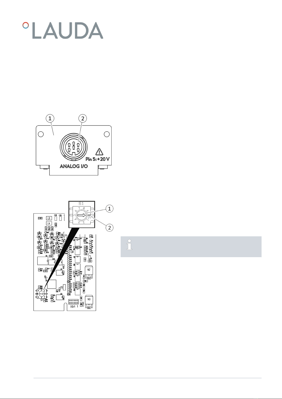
4.2 Structure........................................................................................................................................................................ 9
4.3 Coding switch................................................................................................................................................................ 9
5 Before starting up................................................................................................................................................................ 10
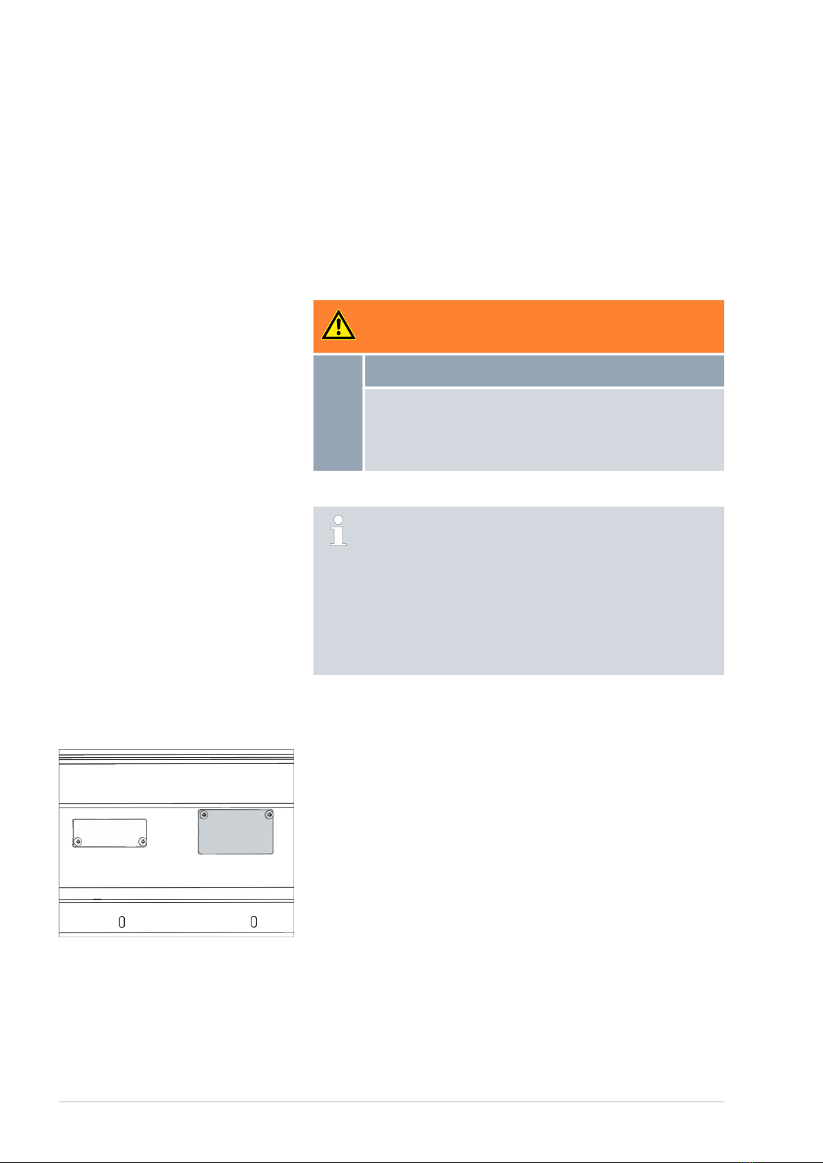
5.1 Installing the interface module................................................................................................................................... 10
5.2 Using the module box.................................................................................................................................................. 12
6 Commissioning..................................................................................................................................................................... 13
6.1 Contact assignment..................................................................................................................................................... 13
6.2 Software update........................................................................................................................................................... 13
7 Operation............................................................................................................................................................................. 14
7.1 Menu structure............................................................................................................................................................ 14
7.2 Interface functions....................................................................................................................................................... 17
7.2.1 Read commands........................................................................................................................................ 17
7.2.2 Write commands....................................................................................................................................... 18
7.2.3 Availability of the interface functions..................................................................................................... 19
7.3 Configuring the interface.......................................................................................................................................... 20
7.4 Calibrating the interface............................................................................................................................................. 21
8 Maintenance........................................................................................................................................................................ 22
9 Faults.................................................................................................................................................................................... 23
10 Decommissioning................................................................................................................................................................ 24
11 Disposal................................................................................................................................................................................ 25
12 Accessories........................................................................................................................................................................... 26
13 Technical data....................................................................................................................................................................... 27
14 Index..................................................................................................................................................................................... 28
V1 Interface module LRZ 912 3 / 28

1 General
Many types of LAUDA constant temperature equipment have vacant
module slots for installing additional interfaces. The number, size and
arrangement of the module slots vary depending on the device and are
described in the operating manual accompanying the constant temperature
equipment. Two additional module slots available as accessories can be fitted
to a LiBus module box, which is then connected as an external casing to the
LiBus interface on the constant temperature equipment.
This operating manual describes how to install and configure the analog
interface module (catalog no. LRZ 912).
Standard signals can be read in and out via the analog interface by way of
a current or voltage. The interface functions provided for this purpose are
described in chapters ÄChapter 7.2.1 “Read commands” on page 17 and
ÄChapter 7.2.2 “Write commands” on page 18.
1.1 Intended use
The interface module can only be operated as intended and under the
conditions specified in this operating manual.
The interface module is an accessory that increases the connections options
of LAUDA constant temperature equipment. It may only be installed in con-
stant temperature equipment that supports the interface provided. Refer to
the chapter "Compatibility” in this operating manual for a list of compatible
product lines.
Operation of the interface module is also permitted in combination with the
LiBus module box (LAUDA catalog no. LCZ 9727). This operating manual
also contains a description of how to install and connect up the module box.
Operation after incomplete assembly
Operation on incompatible constant temperature equipment
Operation using cables or connections that are defective or do not
confirm to standards
1.2 Compatibility
The interface module is available as an accessory for the following LAUDA
product lines:
ECO
Integral XT
Integral IN
PRO
Proline
Variocool
Variocool NRTL
Reasonably foreseeable improper use
V1Interface module LRZ 9124 / 28

Operating interfaces of the same type
Only one analog interface can be used for each item of constant
temperature equipment.
1.3 Technical changes
All technical modifications are prohibited without the written consent of the
manufacturer. Damage resulting from a failure to observe this condition will
void all warranty claims.
However, LAUDA reserves the right to make general technical modifica-
tions.
1.4 Warranty conditions
LAUDA grants a standard warranty of one year.
1.5 Copyright
This operating manual was written in German, checked and approved. If
the content of other language editions deviates from the German edition,
the information in the German edition shall take precedence. If you notice
any discrepancies in the content, please contact LAUDA Service, see
ÄChapter 1.6 “Contact LAUDA” on page 5.
Company and product names mentioned in the operating manual are usually
registered trademarks of the respective companies and are therefore subject
to brand and patent protection. Some of the images used may also show
accessories that are not included in the delivery.
All rights reserved, including those relating to technical modifications and
translations. This operating manual or parts thereof may not be modified,
translated or used in any other capacity without the written consent of
LAUDA. Violation of this may obligate the violator to the payment of dam-
ages. Other claims reserved.
1.6 Contact LAUDA
Contact the LAUDA Service department in the following cases:
Troubleshooting
Technical questions
Ordering accessories and spare parts
Please contact our sales department for questions relating to your specific
application.
Contact information
LAUDA Service
Phone: +49 (0)9343 503-350
Fax: +49 (0)9343 503-283
Email: [email protected]
V1 Interface module LRZ 912 5 / 28

2 Safety
2.1 General safety information and warnings
Read this operating manual carefully before use.
Keep the operating manual in a place within easy reach of the interface
module.
This operating manual is part of the interface module. If the interface
module is passed on, the operating manual must be kept with it.
This operating manual is applicable in combination with the operating
manual of the constant temperature equipment in which the interface
module is installed.
Manuals for LAUDA products are available for download on the
LAUDA website: https://www.lauda.de
The warnings and safety instructions in this operating manual must be
observed without fail.
There are also certain requirements for personnel, see ÄChapter 2.3
“Personnel qualification” on page 7.
Warning signs Type of danger
Warning – danger zone.
Signal word Meaning
DANGER! This combination of symbol and
signal word indicates an imminently
dangerous situation that will result
in death or serious injury if it is not
avoided.
WARNING! This combination of symbol and
signal word indicates a potentially
dangerous situation that can result
in death or serious injury if it is not
avoided.
NOTICE! This combination of symbol and
signal word indicates a poten-
tially dangerous situation that can
result in material and environmental
damage if it is not avoided.
Structure of warnings
V1Interface module LRZ 9126 / 28

2.2 Information about the interface module
Always disconnect the constant temperature equipment from the power
supply before installing the interface module or connecting interfaces.
Always take the recommended safety measures against electrostatic
discharge before handling interface modules.
Avoid touching the circuit board with metallic tools.
Do not start up the constant temperature equipment before installation
of the interface module is complete.
Store any unused interface modules in their packaging in accordance
with the specified ambient conditions.
Use only suitable cables of sucient length for cable connections.
Make sure that the protective screen on the cables and connec-
tors complies with EMC regulations. LAUDA recommends using pre-
assembled cables.
Always lay cables correctly so that they do not pose a tripping hazard.
Secure the laid cables and make sure that they cannot be damaged
during operation.
Check the condition of the cables and interfaces prior to each opera-
tion.
Immediately clean any soiled parts, in particular unused interfaces.
Make sure that the signals transmitted via the interface correspond to
the permitted operating parameters of the interface module.
2.3 Personnel qualification
Only specialized personnel are permitted to install interfaces modules. Spe-
cialized personnel are personnel whose education, knowledge, and experi-
ence qualify them to assess the function and risks associated with the device
and its use.
Specialized personnel
V1 Interface module LRZ 912 7 / 28

3 Unpacking
DANGER!
Transport damage
Electric shock
Closely inspect the device for transport damage prior to
commissioning!
Never operate a device that has sustained transport
damage!
NOTICE!
Electrostatic discharge
Material damage
Always observe safety measures against electrostatic dis-
charge.
Please observe the following installation sequence:
1. Remove the interface module from its packaging.
2. If you want to store the interface module at the installation location,
use the outer packaging. This packaging is protected against static
charging.
3. After installing the equipment, dispose of the packaging materials in
line with environmental regulations, see Ä“Packaging” on page 25.
If you discover any damage on the interface module, contact
LAUDA Service immediately, see ÄChapter 1.6 “Contact
LAUDA” on page 5.
V1Interface module LRZ 9128 / 28

4 Device description
4.1 Purpose
The analog module is designed for installation in constant temperature
equipment that supports the analog interface. Standard signals can be read in
and out via the analog interface by way of a current or voltage.
4.2 Structure
1 Cover with holes for M3x10 fastening screws
26-pin socket, see ÄChapter 6.1 “Contact assignment” on page 13
The analog module has 2 inputs and 2 outputs, which are adapted to the
requirements of the respective constant temperature equipment independ-
ently of one another.
4.3 Coding switch
Valid for analog modules with coding switch:
The printed circuit board of the analog module has a coding switch for
internal addressing.
The adjusting wheel on the analog module must be set to position 0
(factory setting) in order for the module to operate.
Check the coding switch setting before installing the analog module
in constant temperature equipment. If the adjusting wheel does not
indicate position 0, change the setting accordingly.
Change the setting:
1. Use a slotted screwdriver to set the adjusting wheel (1) on the coding
switch.
2. Turn the adjusting wheel (1) to position 0 (2).
Fig. 1: Analog module
Fig. 2: Analog module coding switch
V1 Interface module LRZ 912 9 / 28

5 Before starting up
5.1 Installing the interface module
The interface module is connected to an internal LiBus ribbon cable and
inserted into a vacant module slot. The number and arrangement of the
module slots vary depending on the device. The module slots are protected
by a cover that is screwed onto the casing or attached to the slot opening.
WARNING!
Touching live parts
Electric shock
Disconnect the device from the power supply before
starting any installation work.
Always observe safety measures against electrostatic dis-
charge.
The module installation description essentially applies to all LAUDA
constant temperature equipment; the example diagrams here show
the installation of an analog module in constant temperature equip-
ment from the Variocool product line.
Please note that an interface module with a small cover can only
be installed in a low module slot. The fitted cover must cover the
opening on the module slot completely.
You will require two M3 x 10 screws and a suitable screwdriver to
secure the interface module.
Please observe the following installation sequence:
1. Turn o the constant temperature equipment and pull out the mains
plug.
2. If necessary, remove the screws from the cover on the relevant
module slot. If necessary, use a slotted screwdriver to prise o the
cover.
Fig. 3: Removing the cover (schematic dia-
gram)
V1Interface module LRZ 91210 / 28
Indice
Altri manuali Lauda Apparecchiature di registrazione
Manuali Apparecchiature di registrazione popolari di altre marche

Strymon
Strymon NIGHTSKY Manuale utente

Mitsubishi Electric
Mitsubishi Electric 16CH DIGITAL RECORDER DX-TL5000U Manuale utente

Tews Technologies
Tews Technologies TPMC465 Manuale utente

Honeywell
Honeywell Excel 50 Manuale utente

SeaLevel
SeaLevel COMM+8.LPCI Manuale utente

Arturia
Arturia AUDIOFUSE STUDIO Manuale utente


