LAUNDRY SOLUTION SX205100A Manuale utente

LAUNDRY SOLUTION CO., LTD.
Tel : 076-617171 / 089-7246756 / 086-2762580
Website : www.laundryparts.in.th mail : [email protected]
SX205100A
Dryer Controller
User Manual
Please read the man al caref lly before installation and operation!
Software version
X1.LC001A.X20.001-1 V100A4
Rights Reversed, Pirate P nished
【Safety Precautions】
Installatio
n
Please x the controller to avoid vibrate drops。
Please install the controller in the metal or not
inammable board.
Please guarantee electric cabinet temperature among
-10℃~+50℃ adding the ventilating fan when
necessary.
Do not expose in the sunlight strong airow and mist
Do not expose in corrosive and pollution gas such as
sulde gas salt mist.
Wiring
Please conrm the power supply is OFF.
Let the professional worker to wiring
Signal without source input please do not connect with
power supply
Please increase the system protection, avoids the
controller invalid and cause dangerous.
Please observe the strong and weak electricity
separation principle.
Please use the conforms to the technical standard wire
Please select the parallel method
Parameter According to the machine conguration set the related
parameter guarantees the machine running.
Run
After conrming the wiring correctly then power on.
Guarantee environmental condition and the power
supply voltage is in permit condition only in this way
can start the machine.
When running please do not inspect the signal.
When running please do not change the parameter
setting.
When running please do not approach the machine.
Maintenan
ce,
inspection
The user has any repair needs please contact with
manufacturer do not intend to repair it by yourself.
Please do not pull twist the power line and
communication line.
Please do not touch the controller device directly.
Others Please be careful when simulating and adjusting the
controller on the desk.Presence of high voltage could
cause electrical hazard and injury.
Symbol explanation
Please familiarize yourself with the following standard warning symbols. They are
used throughout this manual to alert you the possible hazards. Anyone installing
operating and servicing this controller must understand these symbols and follow all
the safety rules in this manual.
It ill cause the dangerous situation, possibly ill cause
the personal injury or death hen error using.
It ill cause the dangerous situation, possibly ill lead to
personal injury or death, property damage and economic
loss hen error using.
【Responsibility statement】

In case of any consequence which corrupts or bugs the
controller’s software PUNP reserves the right to repair the
bug but does not have the responsibility to undertake any
compensation.
In case of the controller’s hardware error PUNP has the right
to repair the aw but does not have the duty to undertake
any responsibility.
Because of improper use PUNP does not have the duty to
undertake any responsibility.
PUNP has the right to go to the end user’s service but does
not have the duty.
NOTE:This manual is subject to change ithout separate noti%cation.

Content
1. G N RAL..............................................................................................................................................5
2. INSTALLATION.....................................................................................................................................6
2.1. Dimension....................................................................................................................................6
2.2. lectric connection.......................................................................................................................7
3. FRAME CHART.....................................................................................................................................8
4. BUTTONS INTRODUCTION.................................................................................................................9
5. RUNNING.............................................................................................................................................10
5.1. Startup........................................................................................................................................10
5.2. Idle mode...................................................................................................................................10
5.3. Automatic running mode............................................................................................................10
5.3.1. Start automatic running...................................................................................................10
5.3.2. Change time,temperature................................................................................................10
5.3.3. nding automatic running................................................................................................10
6. PROGRAMMING.................................................................................................................................11
6.1. Select and enter.........................................................................................................................11
6.2. dit.............................................................................................................................................11
6.3. xit and save..............................................................................................................................11
7. PARAMETER.......................................................................................................................................12
7.1. Parameter initialization...............................................................................................................12
7.2. Machine parameter setup..........................................................................................................12
7.3. Modify password........................................................................................................................13
8. ALARM.................................................................................................................................................14
8.1. Alarm reset.................................................................................................................................14
8.2. Alarm information and obviation................................................................................................14

SX205100A Dryer Controller
1. GENERAL
This schematic photo is just for reference!
The controller is specially designed for the control of the automatic dryer. It features stability and
reliability in operation.
The controller has very convenient human-machine interaction interface with liquid crystal display
to show state of operation of the machine including temperatures at Led display and thus helps
monitoring effect.
5 different cycles can be programmed and upon a single touch of the [R n] key, the machine will
run automatically to the end of the selected cycle.
5/16

SX205100A Dryer Controller
2. Installation
2.1. Dimension
6/16

SX205100A Dryer Controller
2.2. Electric connection
220VAC/ 24VDC
L
COM1
220VAC/ 24VDC
COM2
Com1
Fwd
Rev
Heat 1
Heat 2
Fan
Cool
Al arm
Com2
Power input
Gnd
I nput
Emergency Stop
Overheat
Motor overload
Door Single
Gnd
Outdrum temperature
Indrum temperature(Optional)
Wiring chart
123 4 567 8 912
123123 4 1 2345
N
NOTE:Thi drawing i only for reference.
Note:
(1)The diagram above is only for reference.
(2)Voltage outputs of the transformer is AC9.8V (loaded voltage), do not directly connect to AC
220V.
(3)The transformer should be configured by users if the input voltage range of the transformer is
out of the of : AC220V(±10%).
(4)Voltage connected with relay ≤ AC220V (DC 24V); Relay current < 5A
(5)Output to carry an electric voltage for connecting, the customer can connect into according to
own effective demand, needing not certainly AC220V.
(6)Do not use the port standby.
(7)Make sure the temperature around the controller and the connecting cable is lower than 60℃.
7/16

SX205100A Dryer Controller
3. Frame chart
Power on
Startup
Machine Check
Parameter Setup
Idle
Select Program Alarm
Run Program Edit Program
8/16

SX205100A Dryer Controller
4. B ttons introd ction
This schematic photo is j st for reference!
Icon Function
[Start] button
Under “Door Closed” and “Idle” status, press this button to start executing the selected
automatic formula.
[Stop] button
1.Under “auto” Mode, press this button to stop current running formula.
2.When there is an error appeared in the machine, the computer will signal an alarm
automatically with audible sound. Pressing this button will stop audible alarm sound. Press
this button again after troubleshooting. If the error has been resolved or can be ignored, the
computer will go back to “Idle” status. Or else the controller will alarm again.
[Set] button
1.In the count down status, press this button for 3 seconds, you can enter into user
parameter setup.
2.In the idle status, press this button, you can enter into user program edit.
[Up] button
1. When running, you can change motor direction mode, single direction or bi-direction.
2. Under setting status, press this button to choose your desired item.
[Down] button
1. When running, you can change motor direction mode, single direction or bi-direction.
2. Under setting status, press this button to choose your desired item.
9/16
SX205100A Dryer Controller
5. R nning
5.1. Start p
After power is on, the LCD shows the startup interface for 10 seconds. If press [Set] button for 3
seconds during the 10-second-display, you can enter into user parameter setup.
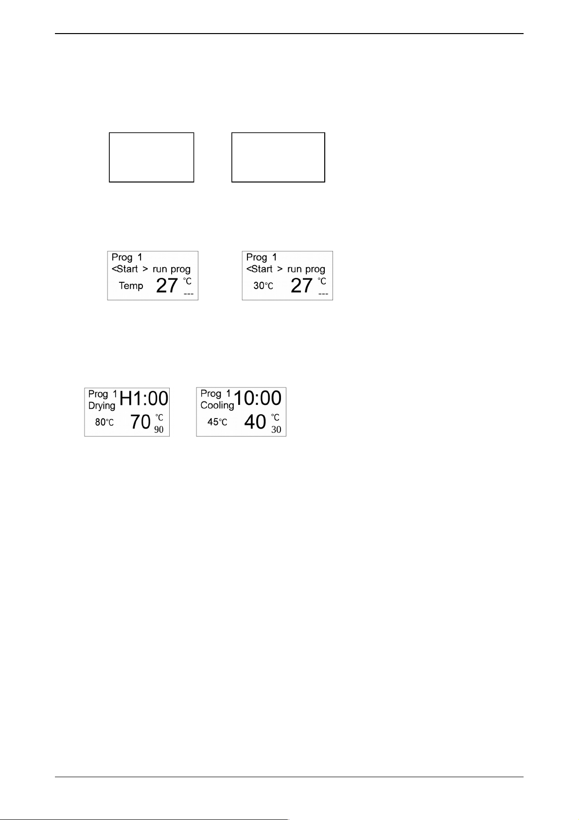
5.2. Idle mode
Not use temp. sensor of in drum Use temp. sensor of in drum
5.3. A tomatic r nning mode
5.3.1. Start a tomatic r nning
On Idle interface, choose your desired program by pressing [Down] or [Up] buttons under “Door
Closed” status, and then press [R n] button to start the program.
Drying Cooling
The left of 1st line, display the current running program number.
The left of 2nd line, display the current running action.
The right of 1st line and 2nd line, display the time.
3rd line and 4th line, display the temperature of in drum and out drum.
5.3.2. Change time,temperat re
Select the setting items by pressing [Set] button and set the value by pressing [Down] or [Up]
button.
5.3.3. Ending a tomatic r nning
After complete cool, the controller becomes ending status. The controller beeps on to clue user,
you can stop the buzzer by pressing [Stop] button during this beeping time.
Note: In the dry process, press [Stop] button to come into cool process. And in the cool process,
press [Stop] button to end the program.
10/16
Auto Dryer
9
X1LC001AX2000
1-1.V100A00
4
Indice
Altri manuali LAUNDRY SOLUTION Controllori


