Lead MRS4616A Manuale utente

4/8/16E1 over Ethernet aggregation Gateway
1
Contents
Contents........................................................................................1
Preface ..........................................................................................2
Chapter One Overview .................................................................3
1.1 Outlet ..................................................................................3
1.2 Equipment Features ............................................................3
Chapter Two Function Specification ............................................4
2.1 Introduction to Front Panel of the Device...........................4
2.2 Introduction to the rear panel of the equipment..................6
Chapter Three Technical Specifications.......................................7
3.1 Operating Environment.......................................................7
3.2 Power Supply Section.........................................................7
3.3 Mechanical Specifications ..................................................7
3.4 E1 Interface.........................................................................7
3.5 Ethernet Interface................................................................7
Chapter four WEB Setting............................................................8
4.1 WEB Login.........................................................................8
4.2 System configuration..........................................................8
Chapter Five Accessories............................................................15
5.1 Method of making lines....................................................15
5.2 Warranty Card...................................................................17

4/8/16E1 over Ethernet aggregation Gateway
2
Preface
Version Description
Manual version: V1.0
Copyright Notice
The copyright of this manual is reserved to our company, who
retains the final rights of explanation and revision to this manual
and notice. No part of this manual may be photocopied, excerpted,
reproduced, revised, transmitted, translated into other languages, or
used for commercial purpose in full or in part, without the prior
written permission of the Company.
Disclaimer
This manual is made according to currently available information
and subject to change without further notice. Whilst every effort has
been made to ensure the accuracy and reliability of the contents
contained herein, the Company cannot be held liable for any harm
or damage resulting from any omissions, inaccuracies or errors
contained in the manual.
Brief Introduction
This User Manual describes the installation and operation of
Ethernet aggregation Gateway Equipment. Before you use our
device for the first time, please read all the included materials
carefully, and install and operate this series of products in keeping
with items listed in the manual, so as to avoid damaging the device
resulting from malpractice. Thank you for choosing our products.
Environmental Protection
This product complies with the design requirements associated with
environmental protection. The storage, use and disposal of the
product should be conducted in accordance with related national
laws and regulations.
We welcome you to put forward advice and suggestion to
our work, which shall be viewed as the ultimate support to us.

4/8/16E1 over Ethernet aggregation Gateway
3
Chapter One Overview
1.1 Outlet
4/8/16E1 over Ethernet aggregation Gateway is a channelized Ethernet
gateway for interconnecting TDM and packet-based networks. The
Ethernet Gateway aggregates and switches Ethernet traffic into 4, 8 or
16 channelized E1 circuits, each supporting up to 31 Ethernet logical
channels (31 over N*64K). Ethernet traffic over channelized E1 lines
is aggregated and transferred to the packet-switched network via the
unit’s Gigabit Ethernet ports. The encapsulation method support
HDLC/PPP-BCP (RFC3518)/GFP-F.
1.2 Equipment Features
Support 4-port Ethernet electrical interfaces, 2- port Ethernet electrical
interfaces or 2-port fiber interface,16-port E1 channel, and make the
Ethernet data gathering into E1 channel.
Support maximum 2047 bytes and provide 2kBytes MAC address
buffer space
Support the Ethernet VLAN isolation function.
Single E1 channel support HDLC/PPP-BCP (RFC3518)/GFP-F
encapsulation, double E1 channel support GFP encapsulation.
Support E1 frame or un-frame application, and N*64K for framed
mode.
Provide Console, Telnet, WEB and SNMP Management.
Support software and firmware upgrade.
-48VDC/220VAC flexible redundant power inputs.

4/8/16E1 over Ethernet aggregation Gateway
4
Chapter Two Function Specification
2.1 Introduction to Front Panel of the Device
Figure1 E1 120Ω,2TX+2FX
Figure2 E1 120Ω,4TX
Figure3 E1 75Ω,2TX+2FX
Figure4 E1 75Ω,4TX
NOTICE: 8E1, only the first 8-way effective
4E1, only the first 4-way effective
2.1.1 Front Panel Indicators Specification
Ethernet

4/8/16E1 over Ethernet aggregation Gateway
5
There are 9 indicators on the front panel of the device, and their functions
are:
NOTICE: LOS LIGHT 8E1, only the first 8-way effective
4E1, only the first 4-way effective
LED
Name
Colors
Functions
Status
Description
PWR
GREEN
Power
Indication
on
Power supply normal
off
Power off
FB2
GREEN
FB2
Indication
on
Fiber connected
flash
Device transmitting
data.
off
Fiber Disconnected
FB1
GREEN
FB1
Indication
on
Fiber connected
flash
Device transmitting
data.
off
Fiber Disconnected
SYS
YELLOW
System status
flash
System working
on
System abnormal
off
System booting
normally
LOS1~16
RED
1-16 Channels
Alarm
on
Channel loss signal
off
Normal
SPD1~4
GREEN
Ethernet
Speed status
on
100M
off
10M
ACT1~4
YELLOW
Ethernet
Activity
flash
Device transmitting
data.
on
Network is established
off
Disconnected

4/8/16E1 over Ethernet aggregation Gateway
6
2.1.2 The front of panel interface description
There are 4 Ethernet electrical interfaces, 2 Ethernet electrical
interfaces or 2 SFP fiber interface, one Console, 4/8/16 E1 interface
and RESET button on the front of panel.
Ethernet Interface
Use the Ethernet Interface with lights.
Reset
The system is in normal operation, if continuously press the Reset
button more than 3 seconds, the system will restore factory default
configuration and reboot.
E1 Interface
Q9(75Ω), RJ45(120Ω)
Console
The device provides a series of Config commands and CLI for
configuring and managing the device. Local Config via the Console
port.
2.2 Introduction to the rear panel of the equipment
Figure of Rear Panel
2.2.1 Power
Two way power interface, 220VAC and -48VDC. When 220VAC,
POWER link L and RETURN link N, when -48VDC, POWER link "+"
and RETURN "-".

4/8/16E1 over Ethernet aggregation Gateway
7
Chapter Three Technical Specifications
3.1 Operating Environment
The device has a wide range of operating temperature and is able to work
normally and stably in highly adverse environment.
Working Temperature 0℃~+50℃
Storage Temperature -40℃~+70℃
Relative Humidity 10 %~95 %
Atmospheric Pressure 70~106 kpa
The environment should be free from corrosive and solvent gases, dust, and
magnetic interference.
3.2 Power Supply Section
Input Voltage:AC 220V/DC 48V
Voltage Fluctuation:100VAC~240VAC/40VDC~72VDC
Power Consumption:<10 W
3.3 Mechanical Specifications
Appearance dimension: 430mm*203mm*44.5mm
3.4 E1 Interface
Interface Impedance:75Ω,120Ω
Connector Type: Q9(75Ω), RJ45(120Ω).
3.5 Ethernet Interface
Fast Ethernet Speed rate: 10M/100M Auto-negotiation、10M half-Duplex、
10M Full Duplex、100M Half-Duplex, 100M Full Duplex Optional.
Support VLAN and QinQ function
IEEE 802.3u auto-negotiation
4/8/16E1 over Ethernet aggregation Gateway
8
Chapter four WEB Setting
4.1 WEB Login
Use IE browser as an example. Open the web browser, input the
default IP address in the address bar: 192.168.0.168.
As below the login dialog, input the right username and password. The
username and password is all “root”.
4.2 System configuration
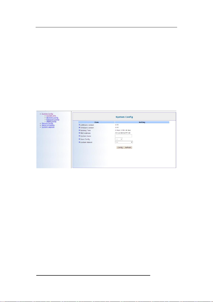
4.2.1 System information
Software Version.
Firmware Version.
Running Time.
MAC Address.
System Name.
System Reboot.
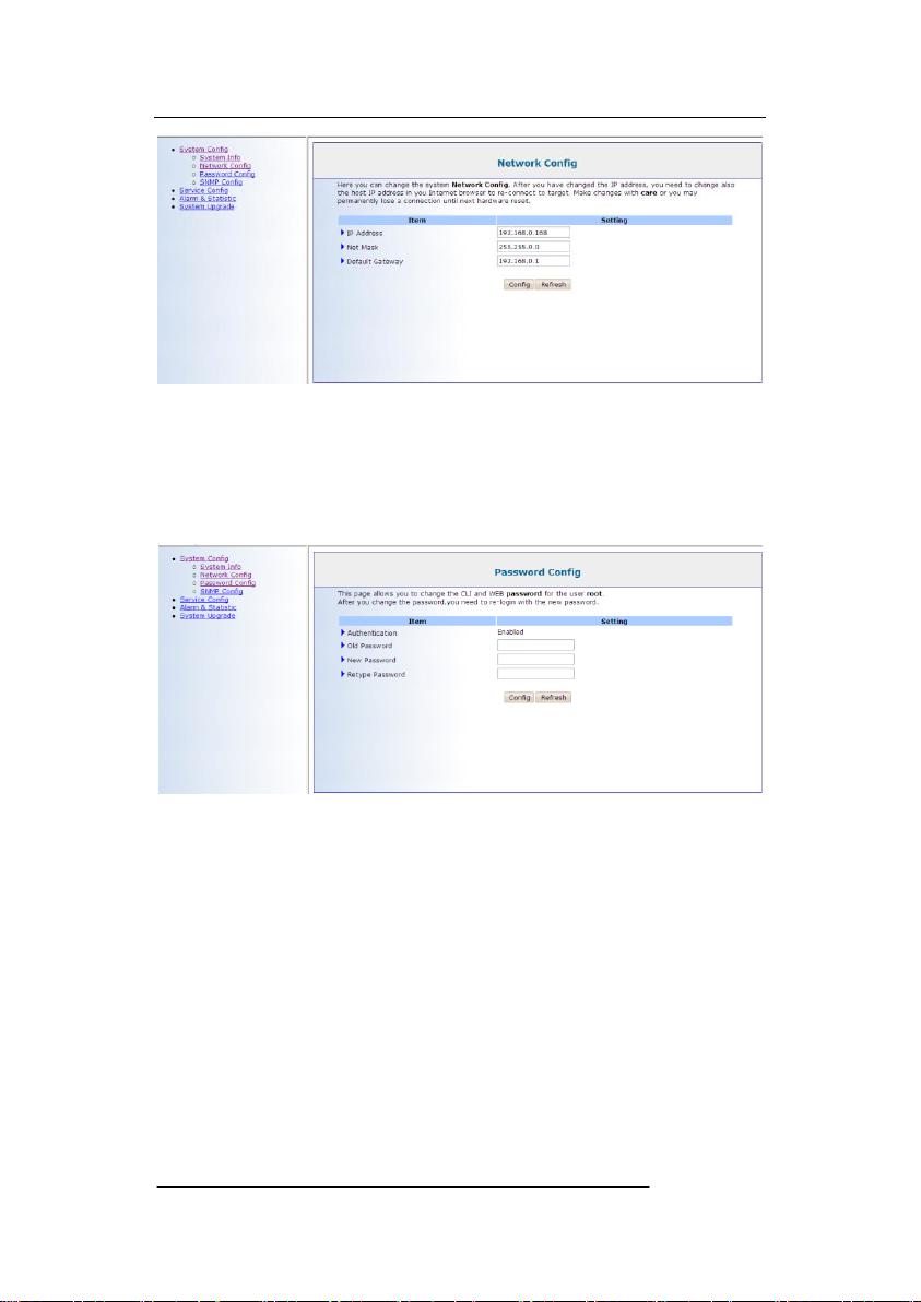
4.2.2 Network configuration
4/8/16E1 over Ethernet aggregation Gateway
9
IPAddress: 192.168.0.168.
Net Mask.
Default Gateway.
4.2.3 Password configuration
User can change password on this page and re-login use the new
password.
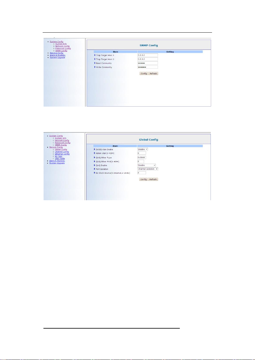
4.2.4 SNMP configuration
4/8/16E1 over Ethernet aggregation Gateway
10
Test SNMP function in this web page.
4.2.5 Global Configuration
Dot1Q Vlan Enable: Vlan&QinQ function enable.
Admin Vlan: User interface VLAN
QinQ Enable: Double Vlan enable.
QinQ Ether Type: Double Vlan type setup.
E1 QinQ Pvid: Double VLAN value.
Ethernet Isolation
4.2.6 Channel configuration
Questo manuale è adatto per i seguenti modelli
2
Indice
Manuali Portale popolari di altre marche

LST
LST M500RFE-AS Manuale utente

Kinnex
Kinnex Media Gateway Manuale utente

2N Telekomunikace
2N Telekomunikace 2N StarGate Manuale utente

Mitsubishi Heavy Industries
Mitsubishi Heavy Industries Superlink SC-WBGW256 Manuale utente

ZyXEL Communications
ZyXEL Communications ZYWALL2 ET 2WE Manuale utente

Telsey
Telsey CPVA 500 - SIP Manuale utente


