Lenovo ThinkServer LPe12000 Manuale utente

HBAInstallationManual
LPe12000,LPe12002andLPe12004

Note:Beforeusingtheinformationandtheproductitsupports,besuretoreadandunderstandthe
AppendixA“Notices”onpage17.
FirstEdition(November2013)
©CopyrightLenovo2013.
LIMITEDANDRESTRICTEDRIGHTSNOTICE:IfdataorsoftwareisdeliveredpursuantaGeneralServicesAdministration
“GSA”contract,use,reproduction,ordisclosureissubjecttorestrictionssetforthinContractNo.GS-35F-05925.

LPe12000, LPe12002 and LPe12004 Hardware Installation Manual Page iii
Table of Contents
Introduction...................................................................................................................................................1
Major Features ................................................................................................................................1
Compatibility....................................................................................................................................1
Prerequisites....................................................................................................................................1
Setting the Jumpers......................................................................................................................................2
Installing the Host Bus Adapter....................................................................................................................3
Attaching Media............................................................................................................................................5
Applying Power.............................................................................................................................................7
Viewing the LEDs ............................................................................................................................7
POST Conditions and Results.........................................................................................................7
References...................................................................................................................................................9
Specifications ..................................................................................................................................9
FCC and Regulatory Notices.........................................................................................................11
Declaration of Conformity..............................................................................................................12
Laser Safety Notice.......................................................................................................................14

LPe12000, LPe12002 and LPe12004 Hardware Installation Manual Page 1
Introduction
This manual describes the Emulex®LPe12000, LPe12002 and LPe12004, 8 gigabit per second (Gb/s)
Fibre Channel (FC) to Peripheral Component Interconnect Express (PCIe) host bus adapters (HBAs).
They feature a revolutionary design with integrated ARM-1156 cores, integrated SERDES, integrated
SRAM, and external Double-Data Rate (DDRII SRAM) memory structure. The LPe12000 is a single-
channel adapter. The LPe12002 is a dual-channel adapter.The LPe12004 is a four-channel adapter.
The core technology of these HBAs is the ninth generation FC controller by Emulex. The controller
incorporates a multifunction native PCIe core that is compliant to the PCIe Base Specification 2.0 and
PCI Express CEM Specification 2.0. The HBAs support packet transfers up to 5 gigatransfers per
second (5.0 GT/s) on the PCIe link. The supported physical PCIe connector is x4 or x8. The fully
featured FC port is compliant to various American National Standards Institute (ANSI) FC standards.
The product is targeted at FC storage networking environments that require the highest degrees of
robustness, performance and ease of management.
Major Features
• Multifunction PCIe 2.0 device with one (LPe12000), two (LPe12002) or four (LPe12004)
independent FC ports
• Auto-negotiation between 2-Gb/s, 4-Gb/s or 8-Gb/s FC link attachments
• Complies with the PCIe base and CEM 2.0 specifications:
• Built-in temperature sensor
Compatibility
Prerequisites
• PCIe 2.0 compliant systems: x4 or x8 lane transfer link interface
• 3.3 V and 12 V power from PCIe slot required for operation
Note: Illustrations in this manual are only examples. The actual hardware may vary.
Table 1. Software and Hardware Environments
Software Environments See the HBA’s Web site for compatible operating systems.
Hardware Environments PCIe 2.0 and CEM 2.0 compliant systems and backwards compatible to 1.0a
and 1.1 compliant systems.

LPe12000, LPe12002 and LPe12004 Hardware Installation Manual Page 2
Setting the Jumpers
The device ID jumpers are used in custom applications. Do not change the jumper settings for a
standard Emulex installation.
The LPe12000 HBA has one six-post jumper block that controls the HBA's device ID. The LPe12002
and LPe12002-X8 HBAs have two six-post jumper blocks that control the HBA's device ID for Ports 0
and 1. The LPe12004 HBA has four six-post jumper blocks that control the HBA's device ID for Ports 0,
1, 2 and 3. Select the ID by installing a jumper between posts 1 and 2, or 3 and 4, or 5 and 6. If no
jumper is installed, the default device ID is 0x1AE5.
Figure 1: The LPe12000, LPe12002 and LPe12004 Jumper Settings
Caution: Emulex LightPulse®HBAs contain electronic components that can be damaged by static
electricity through an electrostatic discharge (ESD) event. To prevent ESD damage, maintain
constant contact with any grounded metal surface. A grounding wrist strap is useful for this
purpose. Handle the card carefully at all times and preferably by the edges. Avoid touching
electronic components and keep the card in the original packaging until you are ready for
installation.
Table 1. Jumper Settings
(Port 0 on the LPe12000 - Ports 0 and 1 on the LPe12002 - Ports 0, 1, 2 and 3 on the LPe12004)
PCI Identifier P0_JX (Port 0) P1_JX (Port 1) P2_JX (Port 2) P3_JX (Port 3)
F100 1–2 1–2 1–2 1-2
F101 3–4 3–4 3-4 3-4
1AE5* 5–6 5–6 5-6 5-6
Note: * Without a jumper, the HBA reports a device ID of 0x1AE5. Most software drivers
require a PCI device ID of F100 to properly identify and control the HBA. Do not
attempt to operate the HBA with the PCI device ID set to 0x1AE5 unless
recommended by the driver installation instructions.

LPe12000, LPe12002 and LPe12004 Hardware Installation Manual Page 3
Installing the Host Bus Adapter
The Emulex LPe12000, LPe12002 and LPe12004 host bus adapters (HBAs) use removable optical
transceivers. If you need to change the bracket for HBA installation, you must first remove the optical
transceiver(s), if installed, from the housing (cage). This document explains how to install the HBA and,
if necessary, how to remove the transceiver and bracket safely.
To install the HBA:
1. Each HBA is shipped with several numbers clearly marked on the board. these include
• IEEE Address
• World Wide Name (WWN)
• Serial number
The IEEE address is a unique 64-bit identifier that you use when configuring your system. The
FC industry uses the WWN derived from the Institute of Electrical and Electronics Engineers
(IEEE) address for FC connectivity. If the adapter has two ports, there are two IEEE addresses
and two WWNs. If the adapter has four ports, there are four IEEE addresses and four WWNs.
Use the serial number when communicating with Emulex. Record these numbers before installa-
tion.
2. Turn off the computer and unplug it.
3. Remove the computer case.
4. Follow steps 5–12 to change the bracket if they are different sizes. Otherwise, skip to step 13.
5. To change the bracket, you must first remove the transceiver from its cage assembly.
The HBA uses different types of transceivers. Figure 2 shows an example of one type showing
the bail (handle) extended.
Figure 2: Example of a transceiver
6. To remove the transceiver, pull the bail (handle) out and down to release the latch and gently pull
the transceiver out. Do not force it. After the latch is released, the transceiver slides out easily.
Note: The HBA comes with a standard PCIe bracket installed. A low-profile bracket is
included in the box with the LPe12000, LPe12002 HBAs. (The LPe12004 will not fit in
a half height slot.) The low-profile mounting bracket is shorter than the standard
bracket; approximately 3.11 in. (7.9 cm) compared to 4.75 in. (12.06 cm) long.
Caution: This is a delicate operation–take care not to damage the transceiver.
bail (handle)

LPe12000, LPe12002 and LPe12004 Hardware Installation Manual Page 4
Figure 3 shows one transceiver partly extracted and the other latched in place.
Figure 3: Removing a transceiver
7. Observing ESD precautions, store the transceiver in an ESD-safe place.
8. Remove the mounting bracket screws from the top of the HBA.
Figure 4: Removing the Bracket
9. Remove the bracket and store it for future use.
10. Align the new mounting bracket tabs with the holes in the HBA.
11. Re-install the screws that attach the HBA to the bracket.
12. Re-install the transceiver by sliding it into the housing. When the latch engages, it clicks.
13. Push the bail back into place.
14. Remove the blank panel from an empty x8 or higher PCIe bus slot.
15. Insert the HBA into the empty slot. Press firmly until the adapter is seated.
16. Secure the HBA's mounting bracket to the case with the panel screw or clip.
17. Replace the computer case and tighten case screws.
The HBA is now installed in the PC and is ready for media attachment.
Note: Be careful not to push the bracket past the transceiver housing's grounding tabs.
Make sure the light emitting diodes (LEDs) are properly aligned with the holes in the
bracket.

LPe12000, LPe12002 and LPe12004 Hardware Installation Manual Page 5
Attaching Media
Use multi-mode fiber optic cable with short-wave SFP+ transceiver, use singe-mode fiber optic cable
with long-wave SFP+ transceiver, that adheres to the following specifications:
Note: The HBA will not allow normal data transmission on an optical link unless it is
connected to another similar or compatible laser product (that is, multimode to
multimode.)
Note: The HBA will not automatically downgrade to the required FC speed based on cable
length. You must downgrade the speed with the appropriate utility or link errors may
occur.
Table 5. Media Specifications
Fiber Optic Cable Maximum Length Minimum Length Connector
OM3 - Multimode 50/125
micron fiber (2000 MHz*km
bandwidth cable)
2.125Gbps: 0.5m - 500m
4.25Gbps: 0.5m - 380m
8.5Gb/s 0.5m – 150m
.5 meters LC
OM2 - Multimode 50/125
micron fiber (500 MHz*km
bandwidth cable)
2.125Gb/s: 0.5m – 300m
4.25Gb/s: 0.5m – 150m
8.5Gb/s 0.5m – 50m
.5 meters LC
OM1 - Multimode 62.5/125
micron fiber (200 MHz*km
bandwidth cable)
2.125Gb/s: 0.5m – 150m
4.25Gb/s: 0.5m – 70m
8.5Gb/s 0.5m – 21m
.5 meters LC
OS1/OS2 – Single-mode 9
micrometer fiber with LC
connectors
2.125Gb/s: 0.5m – 10 km
4.25Gb/s: 0.5m – 10 km
8.5Gb/s 0.5m – 10 km
.5 meters LC

LPe12000, LPe12002 and LPe12004 Hardware Installation Manual Page 6
To attach media to the HBA:
1. Connect a fiber optic cable to an LC connector on the HBA. See figure 6.
Figure 6: Connecting Fiber Optic Cable
2. Connect the other end of the cable to the Fibre Channel device.
After the media is connected to the HBA, you are ready to apply power to the computer.
LPe12000, LPe12002 and LPe12004 Hardware Installation Manual Page 7
Applying Power
To apply power:
1. Verify that the HBA is securely installed in the computer.
2. Verify that the correct media is attached.
3. Plug in the computer and turn it on.
4. Watch the LEDs for Power On Self Test (POST) results.
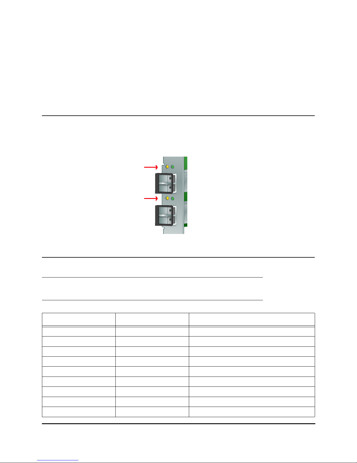
Viewing the LEDs
You can see green and yellow LEDs through openings in the HBA's mounting bracket. The green LED
means firmware operation and the yellow LED means port activity. Each port has a corresponding set of
green and yellow LEDs.
Figure 7: LEDs
POST Conditions and Results
The following table summarizes POST conditions and results:
Note: For the link rate conditions, there is a 1 second pause when the LED is off between
each group of fast blinks (2, 3 or 4). Observe the LED sequence for several seconds
to be sure you have correctly identified the pattern.
Table 8. POST Conditions and Results
Yellow LED Green LED State
Off Off Wake-up failure (dead board)
On Off POST failure (dead board)
Slow Blink Off Wake-up failure monitor
Fast Blink Off POST failure
Flashing Off POST processing in progress
Off On Failure while functioning
On On Failure while functioning
2 Fast Blinks On 2Gb/s link rate-normal, link up
3 Fast Blinks On 4Gb/s link rate-normal, link up
Port 0
LEDs
Port 1
LEDs
Questo manuale è adatto per i seguenti modelli
2
Indice
Manuali Adattatore host popolari di altre marche

Digital Equipment
Digital Equipment StorageWorks EK-KZPCM-UG Manuale utente

ATTO Technology
ATTO Technology ExpressPCI UL4S Manuale utente

Sun Microsystems
Sun Microsystems Sun StorEdge Manuale utente

LSI
LSI LSI21320-R Manuale utente

LSI
LSI Ultra160 Manuale utente

ATTO Technology
ATTO Technology ATTO ExpressPCI FC 3321 Manuale utente


Tekram Technology
Tekram Technology DC-820B Manuale utente

HighPoint
HighPoint RocketRAID 174x Manuale utente

Adaptec
Adaptec AHA-2944UW Manuale utente

ATTO Technology
ATTO Technology ATTO Celerity FC-81EN Manuale utente

ATTO Technology
ATTO Technology UL4D PCI Manuale utente

IBM
IBM System Storage DS4000 Manuale utente