LG AS-H0764DM0 Manuale utente

LG
Room Air Conditioner
SERVICE MANUAL
LG
MODELS: AS-H0764DM0 AS-C0764DM0
AS-H0964DM0 AS-C0964DM0
AS-H1264DM0 AS-C1264DM0
AS-H1865DM0 LS-H0964DL0
AS-H2465DM0 LS-H1264DM0
LS-C1865DM0
LS-C2665DM0
LS-H1865DM0
LS-H2665DM0
CAUTION
website http://www.lgservice.com
• BEFORE SERVICING THE UNIT, READ THE SAFETY
PRECAUTIONS IN THIS MANUAL.
• ONLY FOR AUTHORIZED SERVICE PERSONNEL.

2Room Air Conditioner
Air Conditioner Service Manual
TABLE OF CONTENTS
LG Model Name ...............................................................................................................................................3
Safety Precautions..........................................................................................................................................5
Dimensions....................................................................................................................................................10
Symbols Used in this Manual...................................................................................................................10
Indoor Unit................................................................................................................................................10
Outdoor Unit.............................................................................................................................................12
Product Specifications .................................................................................................................................16
Installation .....................................................................................................................................................20
Selection of the Best Location..................................................................................................................20
Piping Length and Elevation.....................................................................................................................20
How to Fix Installation Plate.....................................................................................................................21
Drill a Hole in the Wall ..............................................................................................................................21
Drain hose junction...................................................................................................................................21
Flaring work and connection of piping .......................................................................................................22
Flaring work..............................................................................................................................................22
Connection of Piping Indoor.....................................................................................................................22
Connection of the Pipes-Outdoor.............................................................................................................26
Connecting the cable between indoor unit and outdoor unit ...................................................................27
Connect the Cable to the Indoor Unit.......................................................................................................27
Connect the Cable to the Outdoor Unit ....................................................................................................28
Checking the drainage and forming the pipings........................................................................................29
Checking the Drainage.............................................................................................................................29
Form the Piping........................................................................................................................................29
AIR PURGING ................................................................................................................................................30
Air purging................................................................................................................................................30
Air purging with vacuum pump .................................................................................................................30
Test Running .................................................................................................................................................32
Operation .......................................................................................................................................................33
Function of Controls .................................................................................................................................33
Display Function ......................................................................................................................................37
Self-diagnosis Function............................................................................................................................37
Remote Control Operations......................................................................................................................38
Disassembly ..................................................................................................................................................39
Indoor Unit................................................................................................................................................39
Schematic Diagram.......................................................................................................................................42
Electric Control Device.............................................................................................................................42
Wiring Diagram.........................................................................................................................................43
Components Location ..............................................................................................................................46
Troubleshooting Guide .................................................................................................................................48
Refrigeration Cycle Diagram ....................................................................................................................48
2-way, 3-way Valve .................................................................................................................................49
Cycle Parts...............................................................................................................................................55
Electronic Parts ........................................................................................................................................56
Exploded View...............................................................................................................................................63
Replacement Parts List ................................................................................................................................65

Service Manual 3
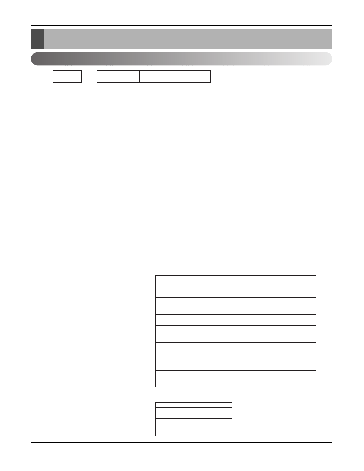
LG Model Name
2003
12 - 345678910
Code Type Code of Model Meaning
1 Producing Center, A~Z L: Chang-won R22 N: India
Refrigerant A: Chang-won R410A Z: Brazil
C: Chang-won R407C D: Indonesia
T: China M: Mexico
K: Turkey R22 V: Vietnam
E: Turkey R410A S: Out Sourcing
H: Thailand
2 Product Type A~Z S: Split Type Air Conditioner
3 Cooling/Heating/Inverter A~Z C: Cooling only
H: Heat pump
X: C/O + E/Heater
Z: H/P + E/Heater
V: AC Inverter C/O
N: AC Inverter H/P
Q: DC Inverter C/O
W: DC Inverter H/P
4, 5 Capacity 0~9 Cooling/Heating Capacity
Ex. "09" →9,000 Btu/h
6 Electric Range 1~9 1: 115V/60Hz, A: 220V, 50Hz, 3Phase
A~Z 2: 220V/60Hz B: 208~230V, 60Hz, 3Phase
3: 208-230V/60Hz C: 575V, 50Hz, 3Phase
5: 200-220V/50Hz D: 440~460, 60Hz, 3Phase
6: 220-240V/50Hz E: 265V, 60Hz
7: 110V, 50/60Hz F: 200V, 50/60Hz
8: 380-415V/50Hz
9: 380-415V/60Hz
7 Chassis A~Z Name of Chassis of Unit
Ex. LSP →SP Chassis
8 Look A~Z Look,
Color (Artcool Model)
9 Function A~Z
10 Serial No. 1~9 LG Model De
* ARTCOOL COLOR
velopment Serial No.
Basic A
Basic+4Way B
Plasma Filter C
Plasma Filter+4 Way D
Tele+LCD E
Tele+LCD+Nano plasma+4Way F
Nano Plasma F+(A/changeove)+A/clean+Low A G
Nano Plasma F+(A/changeove)+A/clean+4way+Low A H
Tele+LED+4way I
Internet J
Plasma F+4Way+Oxy generator K
Nano Plasma F+(A/changeove)+A/clean L
Nano Plasma F+(A/changeove)+A/clean+4way M
Nano Plasma F+(A/changeove)+A/clean+PTC N
Nano Plasma F+(A/changeove)+Autoclean+4way+PTC P
Nano Plasma F+(A/changeove)+A/clean+4way+Low A+PTC Q
Negative ION+A/Clean R
(Nano)Plasma+Negative ION+A/Clean S
4way+(Nano)Plasma F+Negative ION+Healthy dehumidification+A/Clean
T
Nano Plasma F+4Way+(A/changeove)+A/clean+ U
R Mirror
W White
B Blue
D Wood
M Metal
C Cherry

4Room Air Conditioner
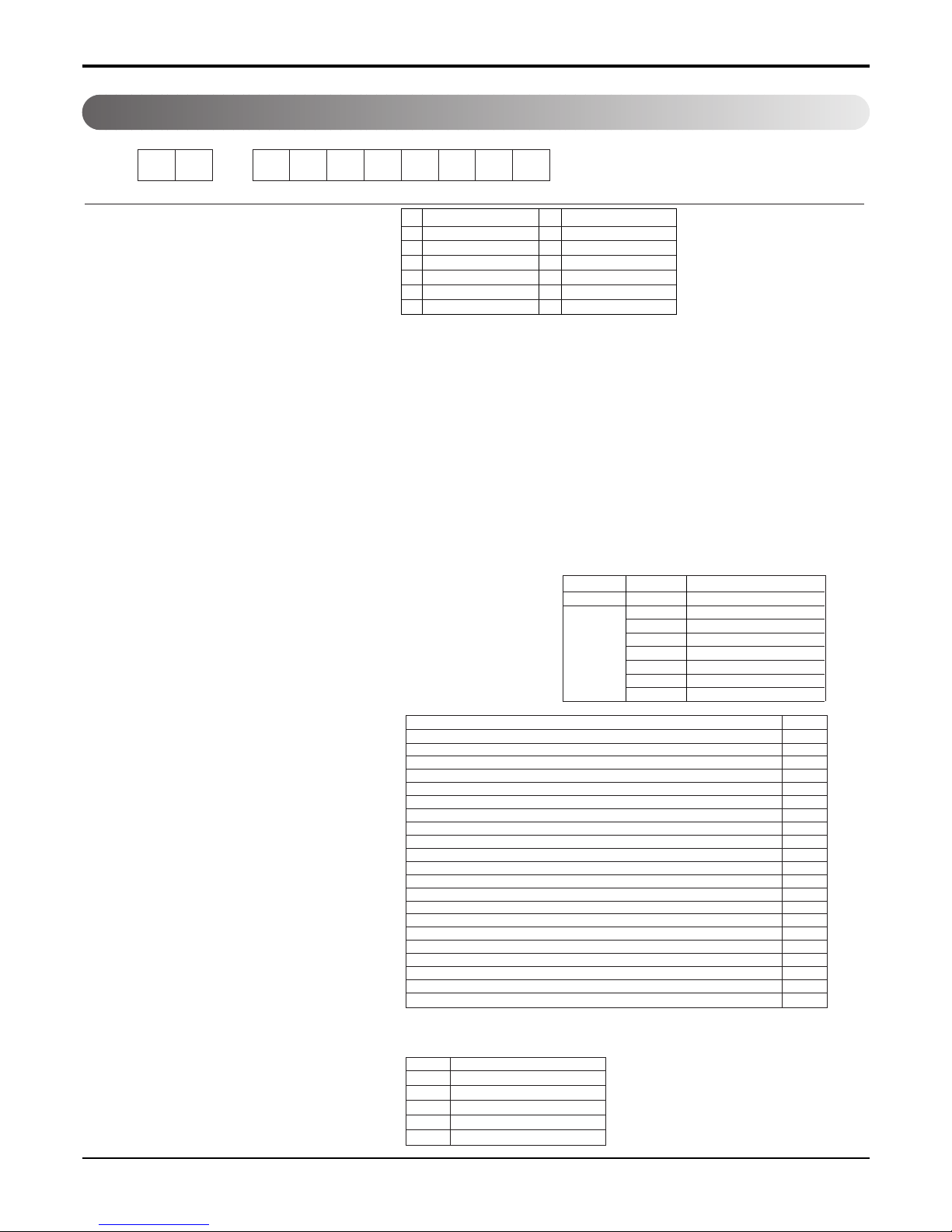
2004~
12 - 345678910
Code Type Code of Model Meaning
1 Producing Center, A~Z
L Chang_won R22
A Chang_won R410A
C Chang_won R407C
T China
K Turkey R22
E Turkey R410A
H Thailand
N India
Z Brazil
D Indonesia
X Mexico
V Vietnam
S Out sourcing
Refrigerant
2 Product Type A~Z S: Split Type Air Conditioner
3 Cooling/Heating/Inverter A~Z C: Cooling only
H: Heat pump
X: C/O + E/Heater
Z: H/P + E/Heater
V: AC Inverter C/O
N: AC Inverter H/P
Q: DC Inverter C/O
W: DC Inverter H/P
4, 5 Capacity 0~9 Cooling/Heating Capacity
Ex. "09" →9,000 Btu/h
6 Electric Range 1~9 1: 115V/60Hz, A: 220V, 50Hz, 3Phase
A~Z 2: 220V/60Hz B: 208~230V, 60Hz, 3Phase
3: 208-230V/60Hz C: 575V, 50Hz, 3Phase
5: 200-220V/50Hz D: 440~460, 60Hz, 3Phase
6: 220-240V/50Hz E: 265V, 60Hz
7: 110V, 50/60Hz F: 200V
CHASSIS Look
D
K
L
G
M
N
D
P
Division
Panel Type(Deluxe)
Fighting 'Look'
(LG1)
(LG2)-SEMI PANEL
OEM1
OEM2
Panel Type(Deluxe)
LG3
, 50/60Hz
8: 380-415V/50Hz
9: 380-415V/60Hz
7 Chassis A~Z Name of Chassis of Unit
Ex. LSP →SP Chassis
8 Look A~Z Look,
Color (Artcool Model)
9 Function A~Z
10 Serial No. 1~9 LG Model De
* ARTCOOL COLOR
velopment Serial No.
R Mirror
W White
B Blue
D Wood
M Metal
C Cherry
S4/S5
S6
SQ
SR
ST
Basic A
Basic+4Way B
Plasma Filter C
Plasma Filter+4 Way D
Tele+LCD E
Tele+LCD+Nano plasma+4Way F
NBF F+(A/changeove)+A/clean+Low A G
NBF F+(A/changeove)+A/clean+4way+Low A H
Tele+LED+4way I
Internet J
Plasma F+4Way+Oxy generator K
NBF F+(A/changeove)+A/clean L
NBF F+(A/changeove)+A/clean+4way M
NBF F+(A/changeove)+A/clean+PTC N
NBF F+(A/changeove)+Autoclean+4way+PTC P
NBF F+(A/changeove)+A/clean+4way+Low A+PTC Q
(Nano)Plasma+ION+A/Clean S
4way+(Nano)Plasma F+
Negative ION+Healthy dehumidification
+A/Clean T
Nano Plasma F+4Way+(A/changeove)+A/clean+Oxy generator U
4way+(Nano)Plasma F+Negative ION+Healthy dehumidification+A/Clean+Oxy generator
V
Dry contact W
Wire remocon 8

Service Manual 5
Safety Precautions
Safety Precautions
To prevent injury to the user or other people and property damage, the following instructions must
be followed.
■Incorrect operation due to ignoring instruction will cause harm or damage. The seriousness is
classified by the following indications.
■Meanings of symbols used in this manual are as shown below.
This symbol indicates the possibility of death or serious injury.
This symbol indicates the possibility of injury or damage to properties only.
Be sure not to do.
Be sure to follow the instruction.
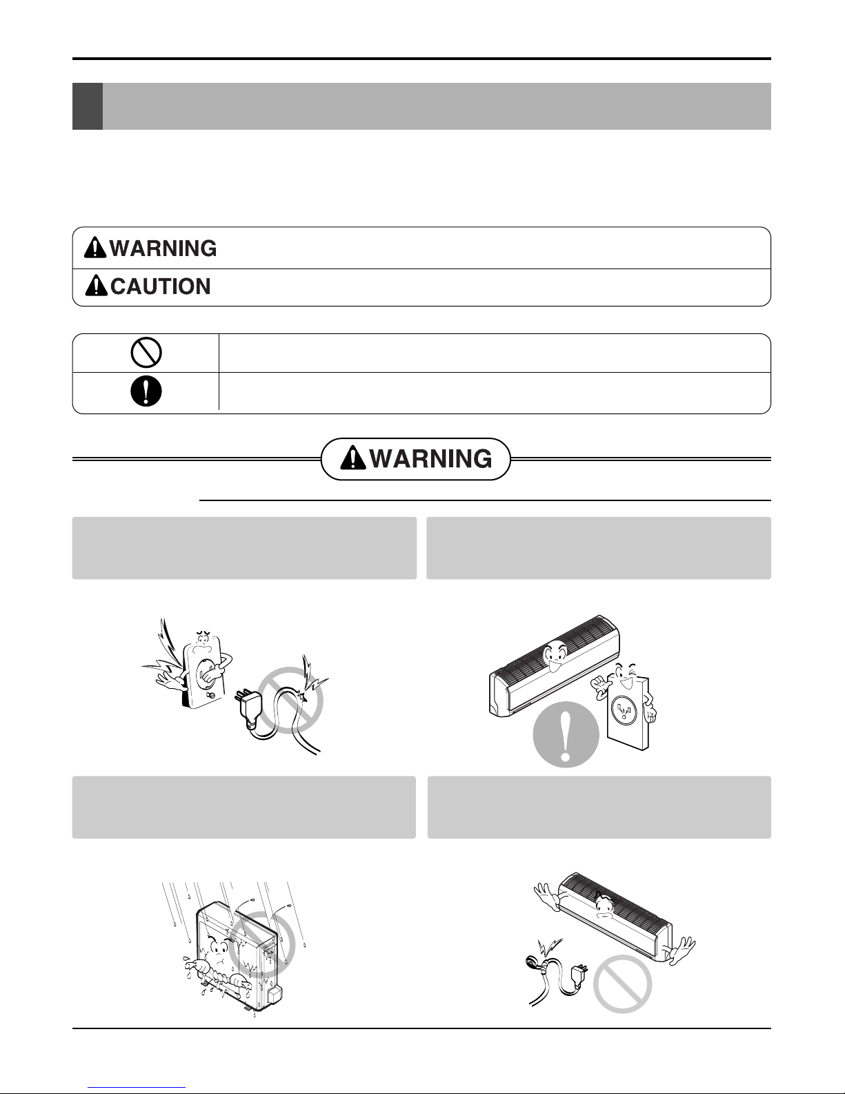
Do not use damaged power cords, plugs, or a
loose socket.
Always use the power plug and socket with the
ground terminal.
• There is risk of fire of electric shock. • There is risk of electric shock.
Install the panel and the cover of control box
securely.
.Do not modify or extend the power cord.
• There is risk of fire of electric shock. • No grounding may cause electric shock.
■Installation

6Room Air Conditioner
Safety Precautions
Do not install the product on a defective instal-
lation stand.
Be sure the installation area does not
deteriorate with age.
• It may cause injury, accident, or damage to the
product.
• If the base collapses, the air conditioner could fall
with it, causing property damage, product failure,
and personal injury.
• Sharp edges could cause injury. Be especially care-
ful of the case edges and the fins on the condenser
and evaporator.
•
There is risk of fire, electric shock, explosion, or injury.
Be cautious when unpacking and installing the
product.
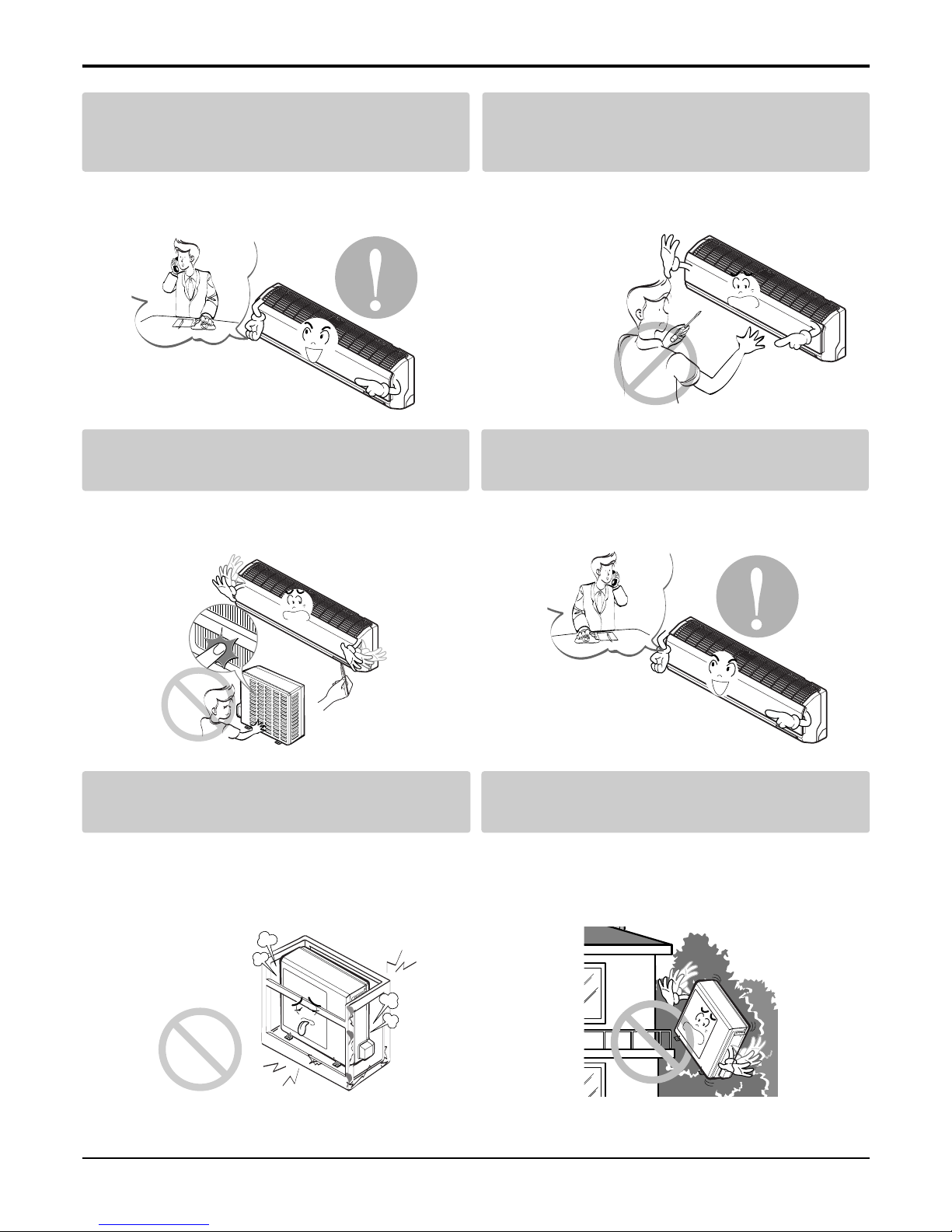
For installation, always contact the dealer or
an Authorized service center
For re-installation of the installed product,
always contact a dealer or an authorized ser-
vice center.
Do not install, remove, or re-install the unit by
yourself.
• There is risk of fire, electric shock, explosion, or
injury.
• There is risk of fire, electric shock, explosion, or
injury.

Service Manual 7
Safety Precautions
■Operation
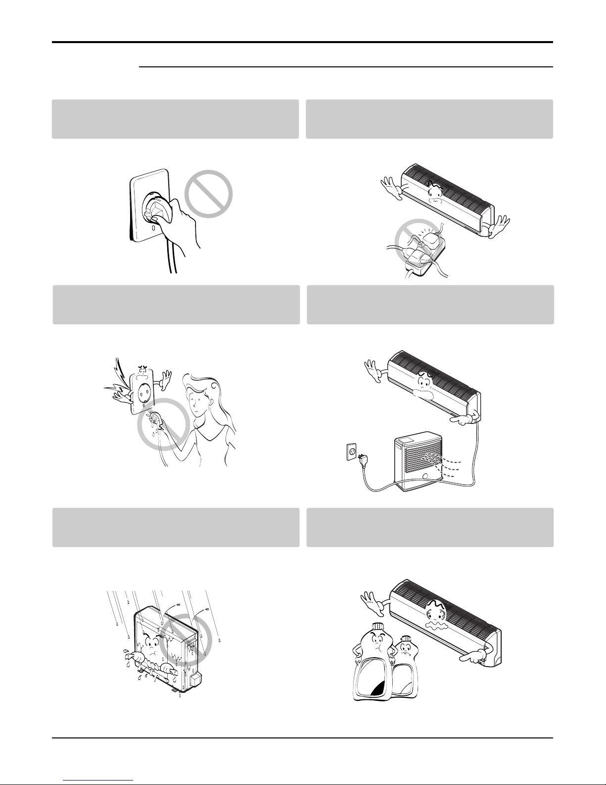
Do not turn the air-conditioner ON or OFF by
plugging or unplugging the power plug.
Use a dedicated outlet for this appliance.
• There is risk of fire or electrical shock. • There is risk of fire or electrical shock.
Grasp the plug to remove the cord from the
outlet. Do not touch it with wet hands.
Do not place a heater or other appliances near
the power cable.
• There is risk of fire or electrical shock. • There is risk of fire and electric shock.
Do not allow water to run into electrical parts. Do not store or use flammable gas or com-
bustibles near the air conditioner.
• There is risk of fire, failure of the product, or electric
shock.
• There is risk of fire or failure of product.
Wax
Thinner

8Room Air Conditioner
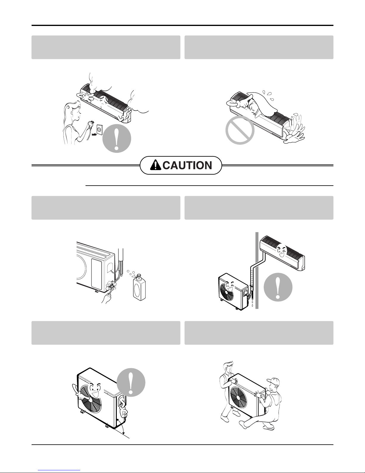
Always check for gas (refrigerant) leakage after
installation or repair of product.
Install the drain hose to ensure that water is
drained away properly.
• Low refrigerant levels may cause failure of product. • A bad connection may cause water leakage.
Keep level even when installing the product. Use two or more people to lift and transport
the air conditioner.
• To avoid vibration or water leakage. • Avoid personal injury.
■Installation
90˚
Unplug the unit if strange sounds, odors, or
smoke comes from it.
Be cautious that water could not enter the
product.
•There is risk of electric shock or fire. •There is risk of fire, electric shock, or product dam-
age.
Safety Precautions

Service Manual 9
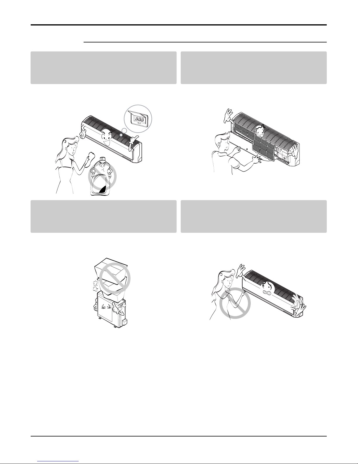
Use a soft cloth to clean. Do not use harsh
detergents, solvents, etc.
Do not touch the metal parts of the product
when removing the air filter. They are very
sharp!
•There is risk of fire, electric shock, or damage to the
plastic parts of the product.
•There is risk of personal injury.
Do not step on or put anyting on the product.
(outdoor units)
Do not insert hands or other objects through
the air inlet or outlet while the air conditioner
is plugged in.
•There is risk of personal injury and failure of product. •There are sharp and moving parts that could cause
personal injury.
■Operation
Wax
Safety Precautions

10 Room Air Conditioner
Dimensions
Dimensions
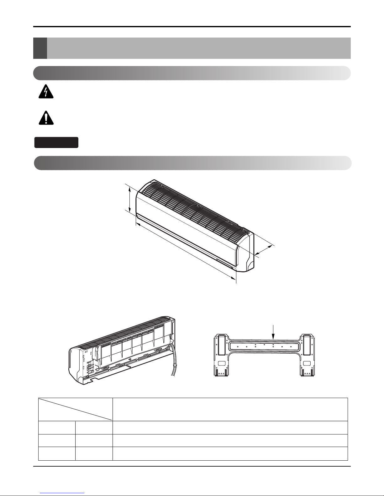
Installation plate
D
H
W
W mm 840
H mm 270
D mm 153
Model
Dimension
7k, 9k, 12k Btu Series
Indoor Unit
This symbol alerts you to the risk of electric shock.
This symbol alerts you to hazards that could cause harm to the
air conditioner.
This symbol indicates special notes.
NOTICE
Symbols Used in this Manual
Questo manuale è adatto per i seguenti modelli
13
Indice
Altri manuali LG Condizionatore d'aria

LG
LG ARNU09GSF11 Manuale utente

LG
LG TS-K1830CL Manuale utente

LG
LG AUUQ18GH1 Manuale utente

LG
LG LWHD1200HR Manuale utente

LG
LG S4NQ18KL3QD Manuale utente

LG
LG AVNQ18GJLA0 Manuale utente

LG
LG ARNU12GB1G2.ENWALEU Manuale utente

LG
LG LF480CE Manuale utente

LG
LG LW1010ER Manuale utente

LG
LG LMU18CHV Manuale utente

LG
LG THERMA V HN1636 Manuale utente

LG
LG MS09SQ Manuale utente

LG
LG LP155CED1 Manuale utente

LG
LG ARNU183TQC2 Manuale utente

LG
LG ARNU 073 SER2 Manuale di installazione e funzionamento

LG
LG TB-H488RSS5 Manuale utente

LG
LG LW2511ER Manuale utente

LG
LG LW2416HR Manuale utente

LG
LG PM12SP NSJ Manuale utente

LG
LG UMNH24GB2A1 Manuale utente