LG L5UC728FA2 Manuale utente

www.lg.com
INSTALLATION MANUAL
AIR CONDITIONER
• Please read this installation manual completely before installing the product.
• Installation work must be performed in accordance with the national wiring
standards by authorized personnel only.
• Please retain this installation manual for future reference after reading it
thoroughly.
P/NO : 3828A20567K

2Multi Type Air Conditioner
Multi Type Air Conditioner Installation Manual
TABLE OF CONTENTS
Installation Parts Provided ........................................3
Safety Precautions ......................................................4
Installation of Indoor, Outdoor Unit...........................7
Wall mounted Type................................................11
Ceiling Concealed Duct Type................................15
Ceiling Cassette Type ...........................................21
Flaring work and connection of piping...................31
Connecting the Cable between Indoor Unit and
Outdoor Unit ..............................................................44
Checking the Drainage, Forming the Pipings
and Long pipe Setting ..............................................46
Air Purging and Evacuation .....................................48
Test running...............................................................50
Optional Operation - Ceiling Concealed Duct Type
..........51
Optional Operation - Ceiling Cassette Type ...........55
Combination indoor units ........................................58
Installation guide at the seaside..............................59
❏Level gauge
❏Screw driver
❏Electric drill
❏Hole core drill (ø70mm)
❏Horizontal meter
❏Flaring tool set
❏Specified torque wrenches
1.8kg.m, 4.2kg.m, 5.5kg.m, 6.6kg.m
(different depending on model No.)
❏Spanner .................Half union
❏A glass of water
❏Screw driver
❏Hexagonal wrench(4mm)
❏Gas-leak detector
❏Vacuum pump
❏Gauge manifold
❏Owner's manual
❏Thermometer
❏Holder Remote Control
Installation Requirements Required Tools

Installation Parts Provided
Installation Manual 3
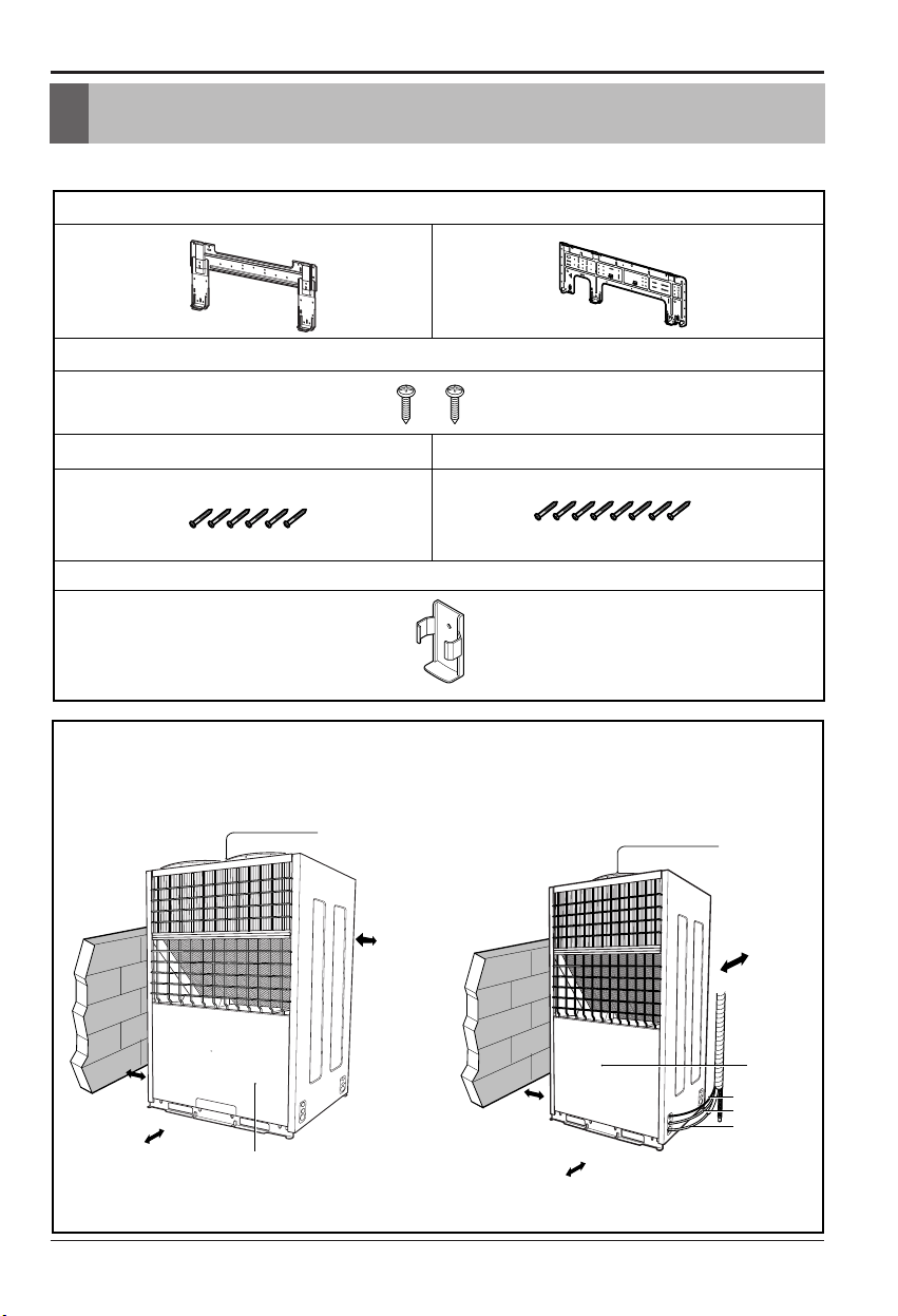
Installation Parts Provided
Outdoor Unit
Wall Mounted Type
more than
25cm
more than
25cm
more than
75cm
more than
25cm
Air Outlet
Control cover
Installation plate
Type "B" screws
Type "A" screw (6 EA) Type "A" screw (8 EA)
Holder Remote Control
more than
25cm
more than
25cm
more than
75cm
more than
25cm
Air Outlet
Connection pipe
Drain hose
Connecting wire
Control cover

4Multi Type Air Conditioner
Safety Precautions
To prevent injury to the user or other people and property damage, the following instructions
must be followed.
■Incorrect operation due to ignoring instruction will cause harm or damage. The seriousness
is classified by the following indications.
■Meanings of symbols used in this manual are as shown below.
WARNING
CAUTION
This symbol indicates the possibility of death or serious injury.
This symbol indicates the possibility of injury or damage.
Be sure not to do.
Be sure to follow the instruction.
Safety Precautions
WARNING
■Installation
Install the panel and the cover of
control box securely.
•There is risk of fire or
electric shock.
Always install a dedicated
circuit and breaker.
•Improper wiring or
installation may cause fire or
electric shock
Use the correctly rated breaker
or fuse.
•There is risk of fire or
electric shock.
Do not use a defective or
underrated circuit breaker. Use
this appliance on a dedicated
circuit.
•There is risk of fire or
electric shock.
For electrical work, contact the
dealer, seller, a qualified
electrician, or an Authorized
Service Center.
•
Do not disassemble or repair
the product. There is risk of
fire or electric shock.
Always ground the product.
•There is risk of fire or
electric shock.

Installation Manual 5
Safety Precautions
Do not modify or extend the power cable.
• There is risk of fire or electric shock.
Be cautious when unpacking and installing the
product.
•
Sharp edges could cause injury. Be especially
careful of the case edges and the fins on the
condenser and evaporator.
For installation, always contact the dealer or an
Authorized Service Center.
• There is risk of fire, electric shock, explosion,
or injury.
Do not install the product on a defective
installation stand.
• It may cause injury, accident,
or damage to the product.
Be sure the installation area does not
deteriorate with age.
•
If the base collapses, the air conditioner could fall with
it, causing property damage, product failure, and
personal injury.
Do not let the air conditioner run for a long time when
the humidity is very high and a door or a window is
left open.
• Moisture may condense and wet or damage
furniture.
Do not store or use flammable gas or combustibles
near the product.
• There is risk of fire or failure of product.
Use a vacuum pump or Inert (nitrogen) gas when
doing leakage test or air purge. Do not compress air
or Oxygen and Do not use Flammable gases.
Otherwise, it may cause fire or explosion.
• There is the risk of death, injury, fire or
explosion.
nOperation

6Multi Type Air Conditioner
Safety Precautions
Always check for gas (refrigerant) leakage after
installation or repair of product.
•Low refrigerant levels may cause failure of
product.
Install the drain hose to ensure that water is
drained away properly.
•A bad connection may cause water leakage.
Keep level even when installing the product.
•To avoid vibration or water leakage.
Do not install the product where the noise or hot air
from the outdoor unit could damage the
neighborhoods.
•It may cause a problem for your neighbors.
Don't let people to lift and transport the
product. (Use fork lift)
•Avoid personal injury.
Do not install the product where it will be
exposed to sea wind (salt spray) directly.
•It may cause corrosion on the product.
Corrosion, particularly on the condenser and
evaporator fins, could cause product
malfunction or inefficient operation.
CAUTION
■Installation

Installation Manual 7
Installation of Indoor, Outdoor Unit
Read completely, then follow step by step.
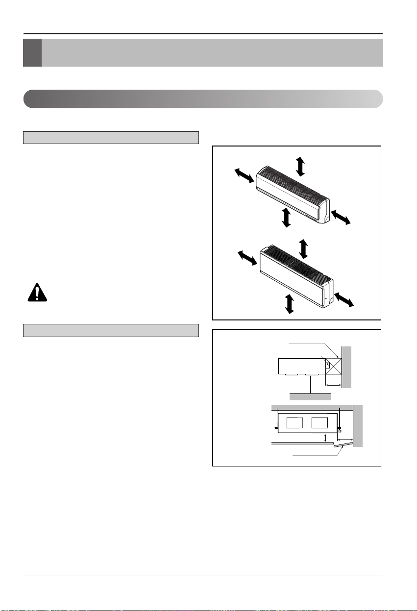
1. Indoor unit
•Do not have any heat or steam near the unit.
•Select a place where there are no obstacles in
front of the unit.
•Make sure that condensation drainage can be
conveniently routed away.
•Do not install near a doorway.
•Ensure the spaces indicated by arrows from
the wall, ceiling, fence or other obstacles.
•Use a stud finder to locate studs to prevent
unnecessary damage to the wall.
Install the air conditioner in the location that
satisfies the following conditions.
•The place shall easily bear a load exceeding
four times the indoor unit’s weight.
•The place shall be able to inspect the unit as
the figure.
•The place where the unit shall beleveled.
•The place shall allow easy water
drainage.(Suitable dimension “H”is necessary
to get a slope to drain as figure.)
•The place shall easily connect with the
outdoor unit.
•The place where the unit is not affected by an
electrical noise.
•The place where air circulation in the room will
be good .
•There should not be any heat source or steam
near the unit
Select the best location
H
600
600
Top view
(unit: mm)
Front view
Front
Inspection Hole
(600X600)
Inspection Hole
(600X600)
Control box
1000
More than 20cm
More than
10cm
More than 2.3m
More than
10cm
More than 20cm
More than
10cm
More than 2.3m
More than
10cm
CAUTION: Install the indoor unit
on the wall where the height from
the floors more than 2.3 meters.
Wall mounted Type
Ceiling Concealed Duct Type

8Multi Type Air Conditioner
Installation of Indoor, Outdoor Unit
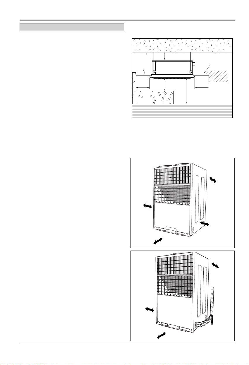
2. Outdoor unit
1. If an awning is built over the unit to prevent
direct sunlight or rain exposure, make sure
that heat radiation from the condenser is not
restricted.
2. Ensure that the spaces indicated by arrows
around front, back and side of the unit.
3. Do not place animals and plants in the path
of the warm air.
4. Take the air conditioner weight into account
and select a place where noise and vibration
are minimum.
5. Select a place so that the warm air and noise
from the air conditioner do not disturb
neighbors.
Rooftop Installations:
If the outdoor unit is installed on a roof
structure, be sure to level the unit. Ensure the
roof structure and anchoring method are
adequate for the unit location. Consult local
codes regarding rooftop mounting.
•There should not be any heat source or steam
near the unit.
•There should not be any obstacles to prevent
the air circulation.
•A place where air circulation in the room will
be good.
•A place where drainage can be easily
obtained.
•A place where noise prevention is taken into
consideration.
•Do not install the unit near the door way.
•Ensure the spaces indicated by arrows from
the wall, ceiling, or other obstacles.
•The indoor unit must keep the maintenance
space.
Unit:mm
Ceiling
Ceiling Board
Ceiling Board
20 or more
1500
or more
500 or
more
H
500 or
more
Floor
Ceiling Cassette Type
more than
75 cm
more than
25 cm
more than
25 cm
more than
25 cm
more than
75cm
more than
25cm
more than
25cm

Installation of Indoor, Outdoor Unit
Installation Manual 9
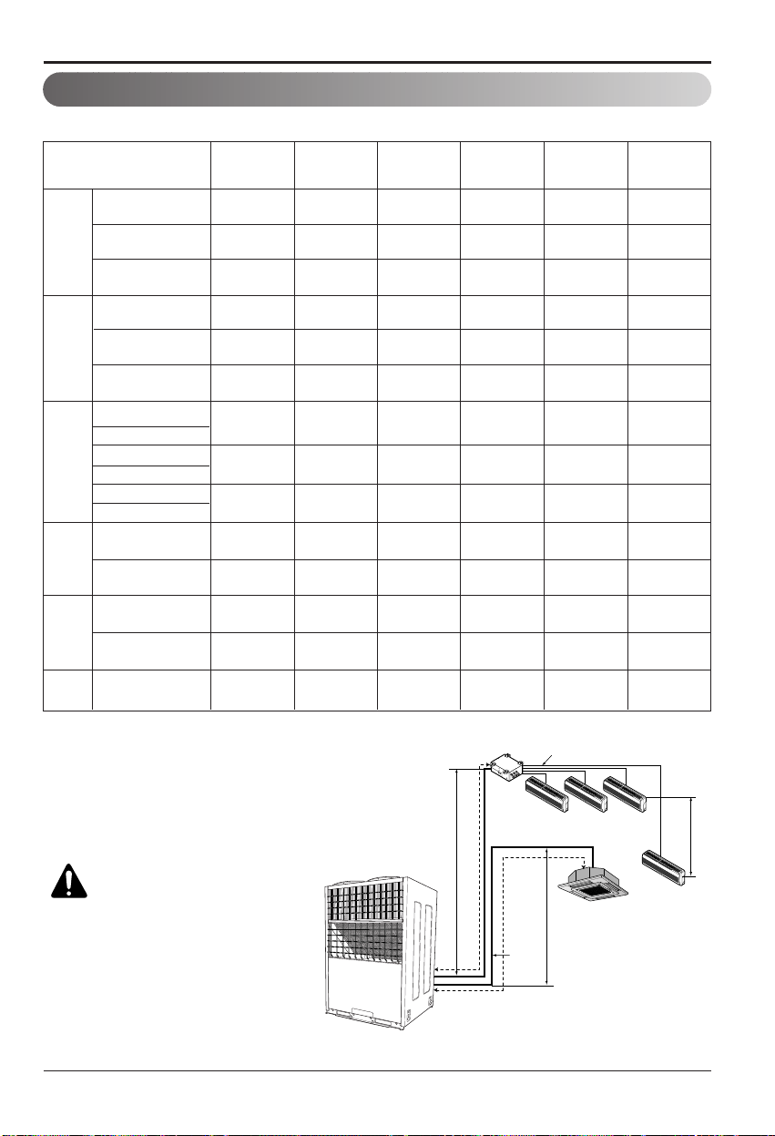
Piping length and elevation table.
Piping length and elevation
60 A = 30 30 15 h1=30 10
50 B = 50 - - h2=30 10
30 B = 30 - - h2=30 10
110 A = 50 60 15 h1=45 10
50 B = 50 - - h2=45 10
45 A = 30 15 15 h1=30 10
50 B = 50 - - h2=30 10
60 A = 30 30 15 h1=30 10
50 A=50 - - h1=30 10
110 A=50 60 15 h1=45 10
50 B=50 - - h2=45 10
110 B=50 60 15 h2=45 10
Total Length Max Main Pipe
Length (A/B)
Total Branch
Pipe Length
Max Branch
Pipe Length
Max Elevation
(h1/h2)
Indoor - Indoor
Elevation (h3)
h3
h1
h2
A
B
Branch Pipe
Main Pipe
Distributor
CAUTION: Capacity is based
on standard length and
maximum allowance length
is on the basis of reliability.
When outdoor unit is at
higher elevation than the
indoor units, after 24m of
vertical height, 1 oil trap is
required.
Model
With Distributor
With Distributor
L5UC7
28FA2
L5UC7
28FA3
L6UH7
28FA2
L8UC1
508FA1
L8UC10
08FA2
L8UH10
08FA2
L8UC10
08FA3
None Distributor
A-Circuit
None Distributor
A-Circuit
With Distributor
With Distributor
With Distributor
None Distributor
None Distributor
None Distributor
B-Circuit
None Distributor
B-Circuit 50 A = 50 - - h1=45 10
60 B = 30 30 15 h2=30 10
With Distributor
A-Circuit
With Distributor
B-Circuit
None Distributor
A-Circuit

10 Multi Type Air Conditioner
Installation of Indoor, Outdoor Unit
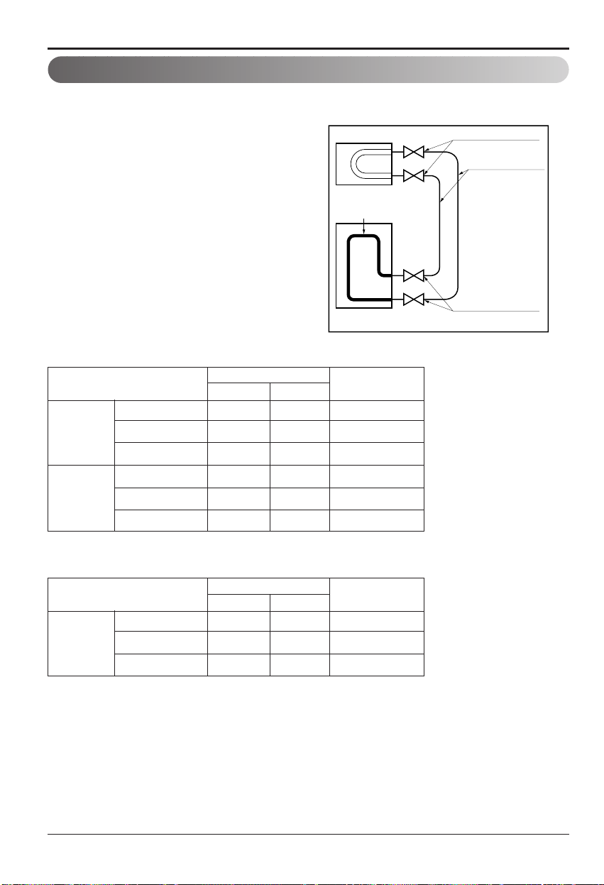
Flared connection (Union)
Flared connection
(Service valve, Ball valve)
Use a seemliness tube
Factory charged
Indoor
Outdoor
Perform the work according to the Service Manual or Installation Guide.
•Use two spanners when connecting the
refrigerant pipe to the unit.
•Make a bend with a radius as large as
possible.
•Perform air purge with R22 or vacuum drying.
•When piping work is finished, check all joints.
■
Add refrigerant if piping over 7.5m as shown
below, non distributor type.
■Add refrigerant if piping over 5m (main pipe),
7.5m (branch pipe) as shown below, distributor
type.
24 kBtu/h 15.88 6.35 30g/m
48/60 kBtu/h 19.05 9.52 50g/m
90 kBtu/h 25.4 12.7 120g/m
12/18 kBtu/h 12.7 6.35 20g/m
24/30/36 kBtu/h
15.88 6.35 30g/m
48 kBtu/h 19.05 9.52 50g/m
Main Pipe
Branch Pipe
Additional
Refrigerant
Pipe
Gas Liquid
Refrigerant piping
Table. Distributor type
12/18 kBtu/h 12.7 6.35 20g/m
24/30/36 kBtu/h
15.88 6.35 30g/m
48 kBtu/h 19.05 9.52 50g/m
Branch Pipe
Additional
Refrigerant
Pipe
Gas Liquid
Table. Non Distributor type
Questo manuale è adatto per i seguenti modelli
6
Indice
Altri manuali LG Condizionatore d'aria

LG
LG RS-Q14BNZE Manuale utente

LG
LG UU36WH Manuale utente

LG
LG Mega LS180HEV2 Manuale utente

LG
LG LW6015ER Manuale utente

LG
LG URNU18GVJA2 Manuale utente

LG
LG MULTI V ARN Series Manuale di installazione e funzionamento

LG
LG LK-0580HC/BC Manuale utente

LG
LG Therma V AHUW056A3 Guida del prodotto

LG
LG LP150HED-Y8 Manuale utente

LG
LG Multi V Series Manuale utente

LG
LG LBNS3061BL Manuale utente

LG
LG AVNQ54LLLA1 Manuale utente

LG
LG V-NET PDRYCB100 Manuale utente

LG
LG G07AH Manuale utente

LG
LG Multi V ARNU36GTNC2 Manuale utente

LG
LG AMNW09GB1A0 Manuale utente

LG
LG UM60F Manuale utente

LG
LG 458004 Manuale utente

LG
LG LW1024RSMX Manuale utente

LG
LG MA09AH1.NF1 Manuale utente