LG LF480CE Manuale utente

LG Floor Standing Type
Air Conditioner
INSTALLATION MANUAL
LG
website http://www.lgservice.com
e-mail http://www.lgeservice.com/techsup.html
IMPORTANT
• Please read this installation manual completely before
installing the product.
• Installation work must be performed in accordance with
the national wiring standards by authorized personnel
only.
• Please retain this installation manual for future reference
after reading it thoroughly.
ENGLISH

2Floor Standing type Air Conditioner
Floor Standing Type Air Conditioner Installation Manual
TABLE OF CONTENTS
Safety Precautions..........................................................................................3
Installation of Indoor, Outdoor Unit ..............................................................6
1) Selection of the best location.................................................................................................................................6
2) Indoor Unit Installation...........................................................................................................................................8
3) Outdoor unit installation.........................................................................................................................................8
4) Refrigerant amount................................................................................................................................................8
5) Installation method procedure................................................................................................................................9
6) Preparation of installation parts and tools ...........................................................................................................10
7) Preparation of piping............................................................................................................................................11
8) Connection of piping............................................................................................................................................12
9) Precautions in bending ........................................................................................................................................12
10) Connecting the cable to the indoor unit.............................................................................................................13
11) Connecting the piping to the outdoor unit..........................................................................................................14
12) Connecting the cable to the outdoor unit...........................................................................................................14
13) Power supply and wiring....................................................................................................................................15
14) Vacuum drying of the connecting pipes and the indoor unit..............................................................................17
15) Form the pipe.....................................................................................................................................................17
Final Check andTest Run..........................................................................................18
OUT-LINE OF INSTALLATION

Safety Precautions
Installation Manual 3
ENGLISH
To prevent injury to the user or other people and property damage, the following instructions
must be followed.
■
Incorrect operation due to ignoring instruction will cause harm or damage.The seriousness
is classified by the following indications.
■Meanings of symbols used in this manual are as shown below.
WARNING
CAUTION
This symbol indicates the possibility of death or serious injury.
This symbol indicates the possibility of injury or damage.
WARNING
Be sure not to do.
Be sure to follow the instruction.
Safety Precautions
■Installation
Install the panel and the cover of
control box securely.
• There is risk of fire or
electric shock.
Always install a dedicated
circuit and breaker.
• Improper wiring or
installation may cause fire or
electric shock
Use the correctly rated breaker
or fuse.
• There is risk of fire or
electric shock.
Do not use a defective or
underrated circuit breaker. Use
this appliance on a dedicated
circuit.
• There is risk of fire or
electric shock.
For electrical work, contact the
dealer, seller, a qualified
electrician, or an Authorized
Service Center.
•
Do not disassemble or repair
the product.There is risk of
fire or electric shock.
Always ground the product.
• There is risk of fire or
electric shock.

4Floor Standing type Air Conditioner
Safety Precautions
Do not modify or extend the power cable.
• There is risk of fire or electric shock.
Be cautious when unpacking and installing the
product.
•
Sharp edges could cause injury. Be especially
careful of the case edges and the fins on the
condenser and evaporator.
For installation, always contact the dealer or an
Authorized Service Center.
• There is risk of fire, electric shock, explosion,
or injury.
Do not install the product on a defective
installation stand.
• It may cause injury, accident, or damage to
the product.
Be sure the installation area does not
deteriorate with age.
•
If the base collapses, the air conditioner could fall with
it, causing property damage, product failure, and
personal injury.
Do not let the air conditioner run for a long time when
the humidity is very high and a door or a window is
left open.
• Moisture may condense and wet or damage
furniture.
Do not store or use flammable gas or combustibles
near the product.
• There is risk of fire or failure of product.
■Operation
Gasolin
Safety Precautions
Installation Manual 5
ENGLISH
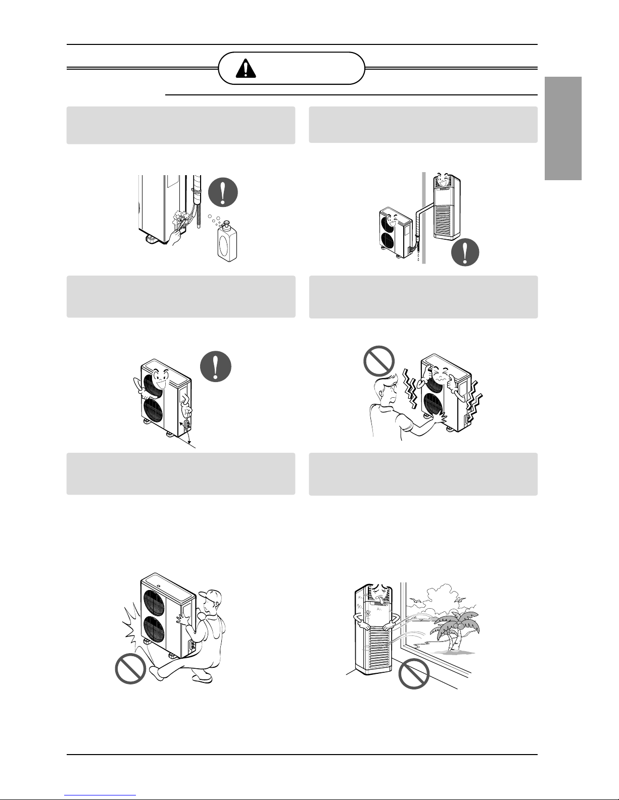
Always check for gas (refrigerant) leakage after
installation or repair of product.
• Low refrigerant levels may cause failure of
product.
Install the drain hose to ensure that water is
drained away properly.
• A bad connection may cause water leakage.
Keep level even when installing the product.
• To avoid vibration or water leakage.
Do not install the product where the noise or hot air
from the outdoor unit could damage the
neighborhoods.
• It may cause a problem for your neighbors.
Use two or more people to lift and transport the
product.
• Avoid personal injury.
Do not install the product where it will be
exposed to sea wind (salt spray) directly.
• It may cause corrosion on the product.
Corrosion, particularly on the condenser and
evaporator fins, could cause product
malfunction or inefficient operation.
CAUTION
90˚
■Installation

6Floor Standing type Air Conditioner
Installation of Unit
Installation of Unit
1. Indoor unit
• There should not be any heat source or
steam near the unit.
• There should not be any obstacles to
prevent the air circulation.
• A place where air circulation in the room
will be good.
• A place where drainage can be easily
obtained.
• A place where noise prevention is taken
into consideration.
• Do not install the unit near the door way.
• Ensure the spaces indicated by arrows
from the wall, ceiling, or other obstacles.
• The indoor unit must keep the
maintenance space.
2. Outdoor unit
• If an awning is built over the unit to prevent
direct sunlight or rain exposure, be careful
that heat radiation from the condenser is
not restricted.
• There should not be any animals or plants
which could be affected by hot air
discharged.
• Ensure the spaces indicated by arrows
from the wall, ceiling, fence or other
obstacles.
Selection of the best location
5cm
40cm
5cm
100cm
More than
50cm
Fence or
obstacles
More than 100cm
More than 50cm
More than
More than
30cm
30cm
More than
50cm
Sunroof

Installation of Unit
Installation Manual 7
ENGLISH
3. Piping length and the elevation
CAUTION:
•Capacity is based on standard length and maximum allowance length is on
the basis of reliability.
•Oil trap should be installed every 5~7 meters.
20K 5/8" 1/4" 25 15
28K/30K/40K 5/8" 3/8" 30 20
44K/48K/50K 3/4" 3/8" 40 25
80K 1" 5/8" 50 30
PIPE SIZE
MODEL
GAS SIDE LIQUID SIDE
Max.
Length
A (m)
Max.
Elevation
B (m)
A
B
Indoor unit
Outdoor unit

8Floor Standing type Air Conditioner
Installation of Unit
The Indoor Unit Installation
Outdoor unit Installation
200mm
70mm 70mm
90mm
Wall
Core Drill
Tilt
Cut if necessary
More than 15mm
Wall
Plastic tube
(Bushing)
INSIDE OUTSIDE
1.The mounting floor should be strong and solid
enough to prevent it from vibration.
2. Drill the piping hole with 70mm diameter hole-
core drill at either the right or the left of indoor
unit. The hole should be sightly slant to the
outdoor side.
3. Insert the plastic tube through the hole.
4. Cut the extruded outside part of the plastic
tube, if necessary.
1. Install the outdoor unit on the concrete or any solid base securely and horizontally by securing it
with bolts (Ø12mm) and nuts.
2. If there is any vibration transmitted to the building, mount the rubber underneath the outdoor unit.
Refrigerant amount
Before shipment, this air conditioner is filled
with the rated amount of refrigerant including
additional amount required for air-purging,
subject to 5m piping length. (The rated amount
of refrigerant is indicated on the name plate.)
But when the piping length exceeds 5 meters,
additional charge is required according to the
following table.
Example) 28K/30K
In case of 10m long pipe(one-way), the amount
of refrigerant to be replenished is:
(10 - 5) x 30 = 150g
(Unit: g)
REFRIGERANT CHARGE
30 per 1m
40 per 1m
80 per 1m
MODEL
20K/28K/30K/40K
(Btu/h)
44K/48K/50K
(Btu/h)
80K
(Btu/h)

Installation Manual 9
ENGLISH
Installation of Unit
Installation Method
No. Installation works Descriptions
1 Preparation of tools and installation parts Preparation of installation
2 Flaring the pipes To insert the flare nuts, mounted on the
connection parts of both indoor and
outdoor unit, onto the copper pipes.
3 Pipe bending To reduce the flow resistance of refrigerant.
4 Connection of installation parts Connection of long piping
(elbows, socket etc)
5 Tighten the flare nut (outdoor) Connecting the pipings of the outdoor unit.
6 Blowing the pipings To remove dust and scale in working.
7 Tighten the flare nut (indoor) Connecting the pipings of the indoor unit.
8 Check a gas-leakage of the connecting
part of the pipings.
9 Vacuum drying of the piping and indoor unit The air which contains moisture and which
remains in the refrigeration cycle may cause a
malfunction on the compressor
10 Open the 3-way (liquid side) and
3-way (gas side) valves.
11 Form the pipings To prevent heat loss and sweat
12 Checking the drainage (indoor unit) To ensure if water flow drain hose of indoor unit.
13 Connecting the cable between outdoor Preparation of the operating
and indoor unit
14 Connecting the main cable to outdoor unit
15 Supply the power to the crankcase heater To prevent the liquid back to the compressor.
(Before the operating the unit) (Heat pump only)
16 Cooling operation
(Use the remote control or display of the
indoor unit)

10 Floor Standing type Air Conditioner
Installation of Unit
Preparation of installation parts and tools
No. Installation Parts,Tools Use
1 Flaring tool (Ø 6.35 - Ø 19.05) Flaring the pipes
2 Remear Remove burrs from cut edges of pipes.
3 Pipe cutter (MAX 35mm Copper pipe) Cutting the pipings
4 Wrench (H5, H4 hexagonal wrench) To open the service valve
5 Pipe bender Bending the pipings
6 Leak detector Check a gas-leakage of connecting part
of the pipings
7 Manifold gauge
To measure the pressure, to charge the refrigerant
8 Charge-nipple To connect the bombe
9 Vacuum pump To remove the air in the pipe.
10 Charge cylinder balance To measure the refrigerant amount
11 Bombe (Freon-22) Gas charge
Cleaning the pipe
12 Spanner To tighten the connecting parts of the pipings
13 Monkey spanner
14 Driver( , )
15 Benchi (150mm) Cutting the wires
16 Tapeline To measure the length
17 Core drill
To make holes through the concrete wall and blocks
18 Voltmeter, Amperemeter, Clampmeter To measure the current and voltage
19 Insulation resistance tester To measure the insulation resistance
20 Glass thermometer
To measure the intake and outlet air temperature of the indoor unit
21 Copper tubes To use the connecting pipings
22 Insulation material To cover the connecting pipings
23 Tape To finish the connecting pipings
24 Electrical Leakage Breaker To shut off the main power
25 Cable
To connect the cable from outdoor unit to indoor unit
26 Drain hose sockets, elbows To remote the condensing water
Altri manuali per LF480CE
2
Indice
Altri manuali LG Condizionatore d'aria

LG
LG LC8000 Manuale utente

LG
LG P12AWN Manuale utente

LG
LG Multi V Manuale utente

LG
LG A09AWU Manuale utente

LG
LG Multi V ARNU073B3G2 Manuale utente

LG
LG CV-H186BLB0 Manuale utente

LG
LG LSN090HEV1 Manuale utente

LG
LG LV-B18 C Series Manuale utente

LG
LG PDI Premium PQNUD1S40 Istruzioni operative

LG
LG PATX20A0E Manuale utente


