
LG RAD-183A Manuale utente

LG
Room
Air Conditioner
SERVICE MANUAL
LG
MODEL: WG1805RY6,RAD-183A
WG2405RY6,RAD-243A
CAUTION
website http://www.lgservice.com
• BEFORE SERVICING THE UNIT, READ THE SAFETY
PRECAUTIONS IN THIS MANUAL.
• ONLY FOR AUTHORIZED SERVICE PERSONNEL.

2Room Air Conditioner
Air Conditioner Service Manual
TABLE OF CONTENTS
Safety Precautions..........................................................................................................................................3
Dimensions .....................................................................................................................................................5
Symbols Used in this Manual.....................................................................................................................5
Outside Dimensions...................................................................................................................................5
Product Specifications ..................................................................................................................................6
Installation.......................................................................................................................................................7
Select the Best Location ...........................................................................................................................7
Installation Check.......................................................................................................................................7
How to Secure the Drain Pipe....................................................................................................................7
Window Requirements...............................................................................................................................8
Installation Kits Contents............................................................................................................................8
Suggested Tool Requirements...................................................................................................................9
Cabinet Installation...................................................................................................................................10
Operation ......................................................................................................................................................12
Features...................................................................................................................................................12
Control Locations Function of Controls....................................................................................................12
Disassembly ..................................................................................................................................................14
Mechanical Parts......................................................................................................................................14
Air Handling Parts ....................................................................................................................................15
Electrical Parts .........................................................................................................................................16
Refrigerating Cycle...................................................................................................................................18
Schematic Diagram.......................................................................................................................................21
Electronic Control Device.........................................................................................................................21
Wiring Diagram.........................................................................................................................................22
Components Lation..................................................................................................................................23
Troubleshooting Guide.................................................................................................................................24
Piping System ..........................................................................................................................................24
Troubleshooting Guide .............................................................................................................................25
Room Air Conditioner Voltage Limits........................................................................................................31
Exploded View ..............................................................................................................................................34
Replacement Parts List ................................................................................................................................36
Service Manual 3
Safety Precautions
Safety Precautions
To prevent injury to the user or other people and property damage, the following instructions must
be followed.
■Incorrect operation due to ignoring instruction will cause harm or damage. The seriousness is
classified by the following indications.
■Meanings of symbols used in this manual are as shown below.
WARNING
CAUTION
This symbol indicates the possibility of death or serious injury.
This symbol indicates the possibility of injury or damage to property only.
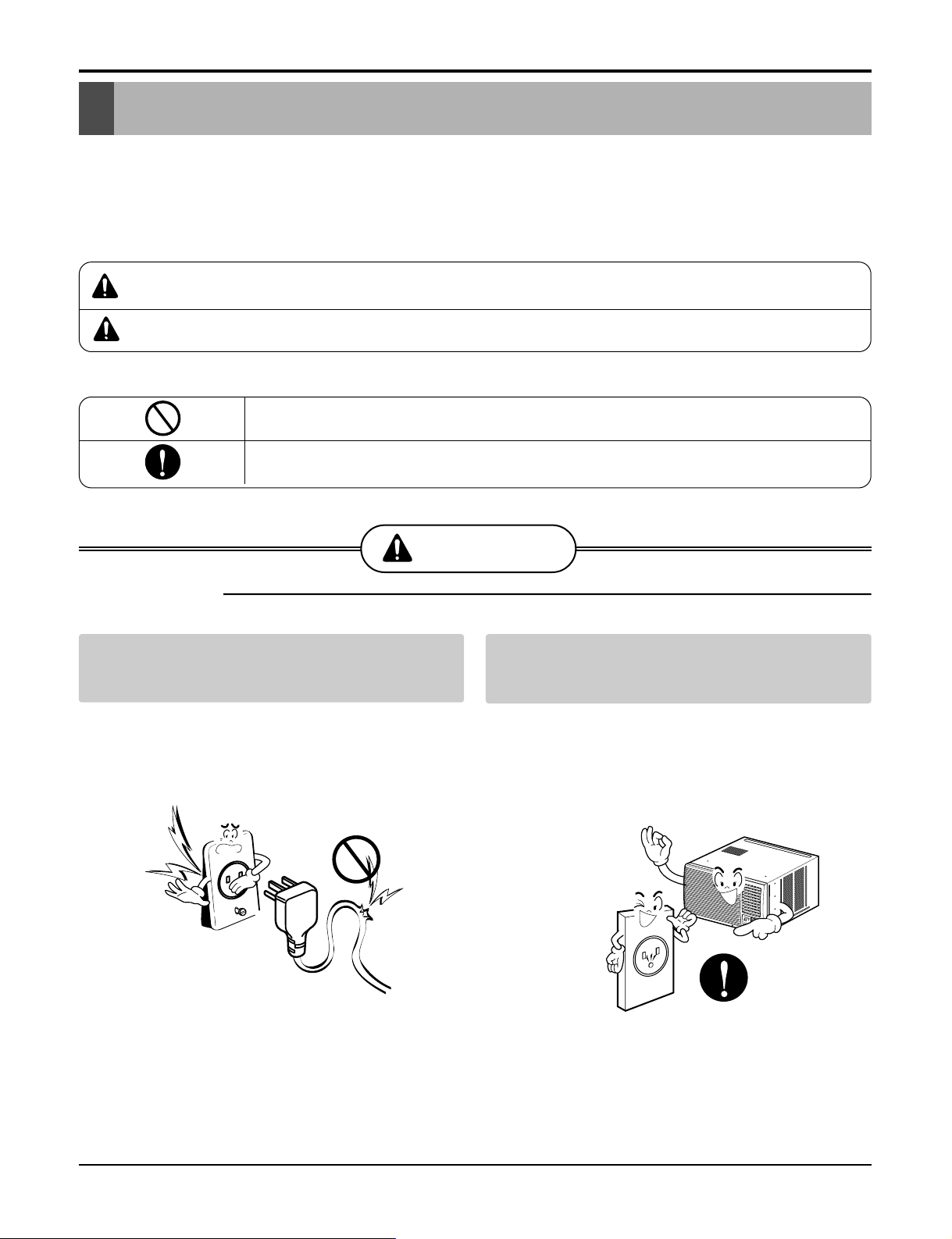
WARNING
■Installation
Do not use damaged power cord plugs, or a
loose socket.
• There is risk of fire or electric shock.
Always use the power plug and socket with
the ground terminal.
• There is risk of electric shock.
Be sure not to do.
Be sure to follow the instruction.
4Room Air Conditioner
Safety Precautions
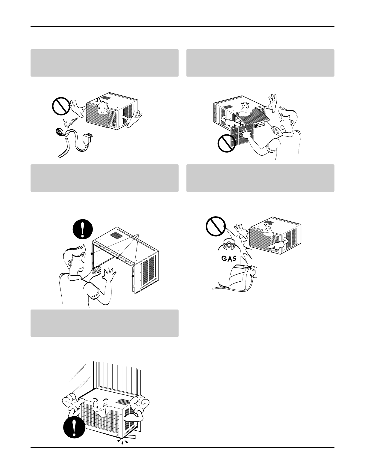
Do not modify or extend the power cord.
• There is risk or fire or electric shock.
Do not install, remove, or re-install the unit by
yourself.
• There is risk of fire, electric shock, explosion, or injury.
Be cautious when unpacking and installing
the product.
• Sharp edges could cause injury. Be especially careful
of the case edges and the fins on the condenser and
evaporator.
Do not store or use flammable gas or com-
bustibles near the air conditioner.
• There is risk of fire or failure of product.
Be sure the installation area does not deterio-
rate with age.
• If the base collapses, the air conditioner could fall with
it, causing property damage, product failure, and per-
sonal injury.
Gasolin
Sharp edges
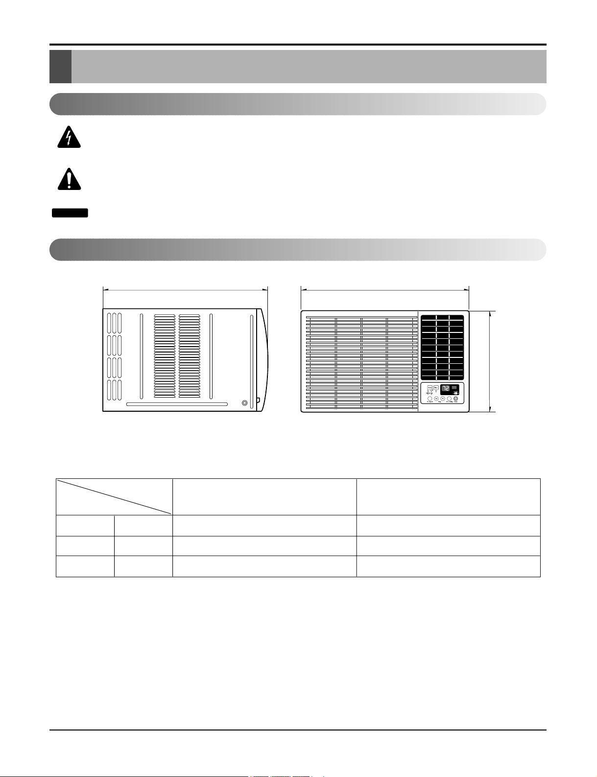
Dimensions
Dimensions
675 (770) 660
428
W mm(inch) 660(26") 660(26")
H mm(inch) 428(16 27/32") 428(16 27/32")
Dmm(inch) 675(269/18") 675(269/18")
Model
Dimension
18K Btu 24K Btu
Outside Dimensions
This symbol alerts you to the risk of electric shock.
This symbol alerts you to hazards that could cause harm to the
air conditioner.
This symbol indicates special notes.
NOTICE
Symbols Used in this Manual
Service Manual 5
6Room Air Conditioner
Specfications
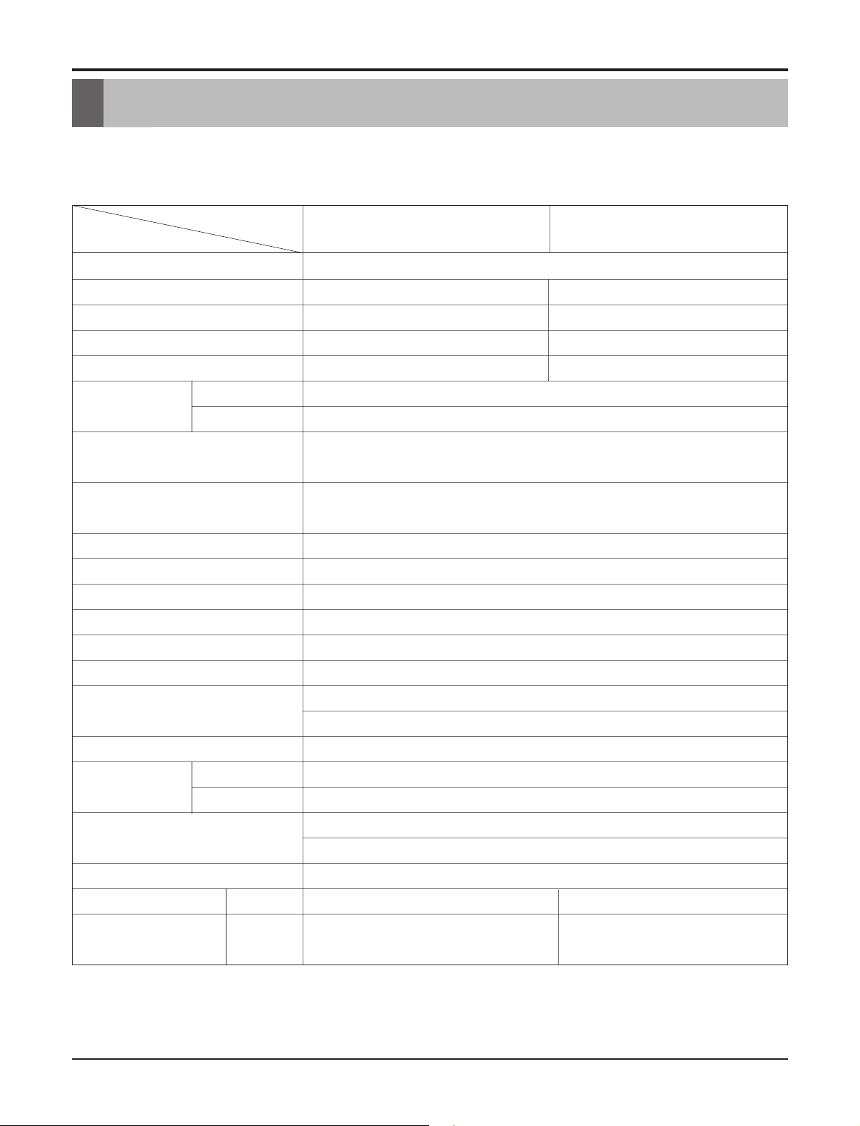
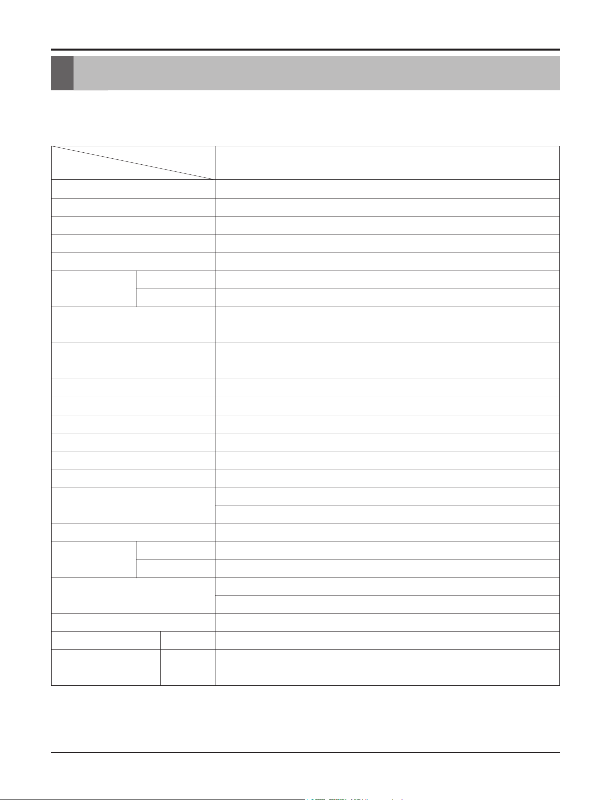
Product Specifications
POWER SUPPLY
COOLING CAPACITY
INPUT
RUNNING CURRENT
REFRIGERANT (R-22) CHARGE(g)
OPERATING INDOOR(°C)
TEMPERATURE OUTDOOR(°C)
EVAPORATOR
CONDENSER
FAN, INDOOR
FAN, OUTDOOR
FAN SPEEDS, FAN/COOLING
FAN MOTOR
OPERATION CONTROL
ROOM TEMP. CONTROL
AIR DIRECTION CONTROL
CONSTRUCTION
PROTECTOR COMPRESSOR
FAN MOTOR
POWER CORD
DRAIN SYSTEM
NET WEIGHT (lbs/kg)
OUTSIDE DIMENSION (inch)
(W x H x D) (mm)
MODELS
ITEMSWG1805RY6WG2405RY7
Table -1
1Ø, 208/230V, 60Hz
17,500/18,000 23,500/23,800
1,800/1,850 2,760/2,800
9.7 8.5
720g(25.4oz) 830g(29.3oz)
27(DB),19(WB)
35(DB),24(WB)
2 ROW 15 STACKS
LOUVERED-FIN TYP
2 ROW 19 STACKS,LOUVERED-FIN TYPE
TURBO
PROPELLER TYPE FAN WITH SLINGER-RING
3/3
6 POLES
WIRELESS REMOCN
THERMISTOR
VERTICAL LOUVER(RIGHT & LEFT)
HORIZONTAL LOUVER(UP & DOWN)
SLIDE IN-OUT CHASSIS
INTERNAL OVERLOAD PROTECTOR
INTERNAL THERMAL PROTECTOR
3 WIRE WITH GROUNDING
CORD-CONNECTED TYPE(ATTATCHMENT PLUG:OPTION)
DRAIN PIPE OR SPLASHED BY FAN SLINGER
130/60 147.7/67
26 x 16 27/32 x 26 9/16 26 x16 27/32 x 30 5/16
660 x 428 x 675 660 x 428 x 675
L-BENDING TYPE
7Room Air Conditioner
Specfications
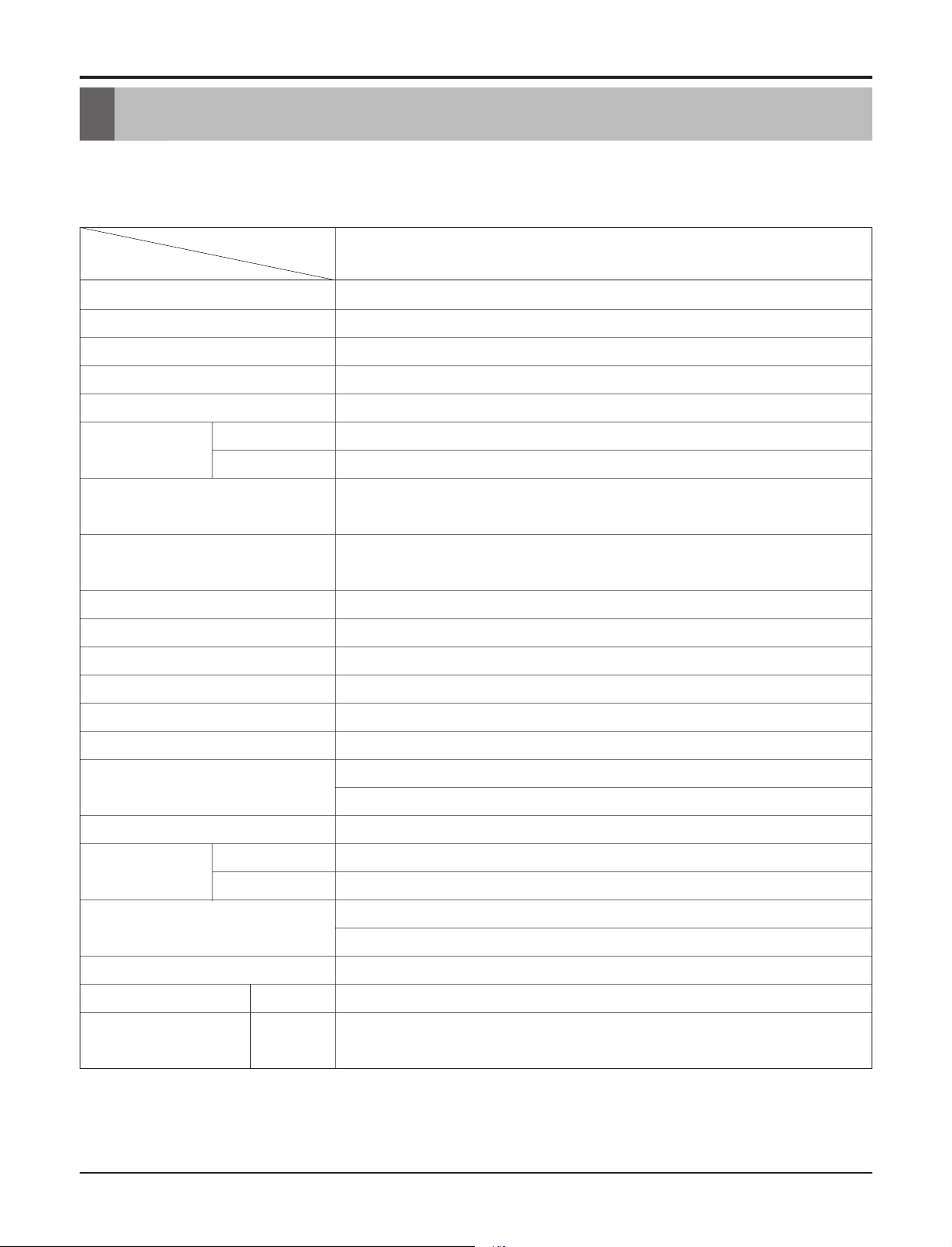
Product Specifications
POWER SUPPLY
COOLING CAPACITY
INPUT
RUNNING CURRENT
REFRIGERANT (R-22) CHARGE(g)
OPERATING INDOOR(°C)
TEMPERATURE OUTDOOR(°C)
EVAPORATOR
CONDENSER
FAN, INDOOR
FAN, OUTDOOR
FAN SPEEDS, FAN/COOLING
FAN MOTOR
OPERATION CONTROL
ROOM TEMP. CONTROL
AIR DIRECTION CONTROL
CONSTRUCTION
PROTECTOR COMPRESSOR
FAN MOTOR
POWER CORD
DRAIN SYSTEM
NET WEIGHT (lbs/kg)
OUTSIDE DIMENSION (inch)
(W x H x D) (mm)
MODELS
ITEMS RAD-183A
Table -1
1Ø, 208/230V, 60Hz
17,500/18,000
1,800/1,850
9.7
720g(25.4oz)
27(DB),19(WB)
35(DB),24(WB)
2 ROW 15 STACKS
LOUVERED-FIN TYP
2 ROW 19 STACKS,LOUVERED-FIN TYPE
TURBO
PROPELLER TYPE FAN WITH SLINGER-RING
3/3
6 POLES
WIRELESS REMOCN
THERMISTOR
VERTICAL LOUVER(RIGHT & LEFT)
HORIZONTAL LOUVER(UP & DOWN)
SLIDE IN-OUT CHASSIS
INTERNAL OVERLOAD PROTECTOR
INTERNAL THERMAL PROTECTOR
3 WIRE WITH GROUNDING
CORD-CONNECTED TYPE(ATTATCHMENT PLUG:OPTION)
DRAIN PIPE OR SPLASHED BY FAN SLINGER
130/60
26 x 16 27/32 x 26 9/16
660 x 428 x 675
L-BENDING TYPE
7Room Air Conditioner
Specfications
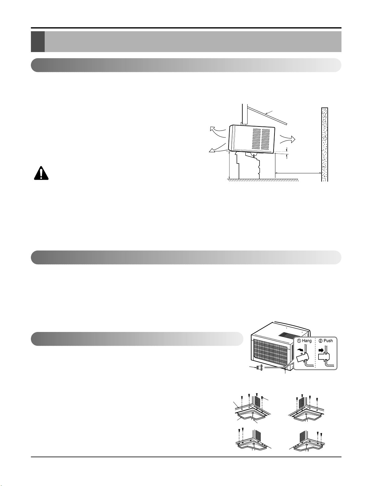
Product Specifications
POWER SUPPLY
COOLING CAPACITY
INPUT
RUNNING CURRENT
REFRIGERANT (R-22) CHARGE(g)
OPERATING INDOOR(°C)
TEMPERATURE OUTDOOR(°C)
EVAPORATOR
CONDENSER
FAN, INDOOR
FAN, OUTDOOR
FAN SPEEDS, FAN/COOLING
FAN MOTOR
OPERATION CONTROL
ROOM TEMP. CONTROL
AIR DIRECTION CONTROL
CONSTRUCTION
PROTECTOR COMPRESSOR
FAN MOTOR
POWER CORD
DRAIN SYSTEM
NET WEIGHT (lbs/kg)
OUTSIDE DIMENSION (inch)
(W x H x D) (mm)
MODELS
ITEMSRAD-243A
Table -1
1Ø, 208/230V, 60Hz
23,500/23,000
2,760/2,710
8.5
835g(29.3oz)
27(DB),19(WB)
35(DB),24(WB)
2 ROW 15 STACKS
LOUVERED-FIN TYP
2 ROW 19 STACKS,LOUVERED-FIN TYPE
TURBO
PROPELLER TYPE FAN WITH SLINGER-RING
3/3
6 POLES
WIRELESS REMOCN
THERMISTOR
VERTICAL LOUVER(RIGHT & LEFT)
HORIZONTAL LOUVER(UP & DOWN)
SLIDE IN-OUT CHASSIS
INTERNAL OVERLOAD PROTECTOR
INTERNAL THERMAL PROTECTOR
3 WIRE WITH GROUNDING
CORD-CONNECTED TYPE(ATTATCHMENT PLUG:OPTION)
DRAIN PIPE OR SPLASHED BY FAN SLINGER
130/60
26 x 16 27/32 x 26 9/16
660 x 428 x 675
L-BENDING TYPE
Service Manual 8
Installation
Installation
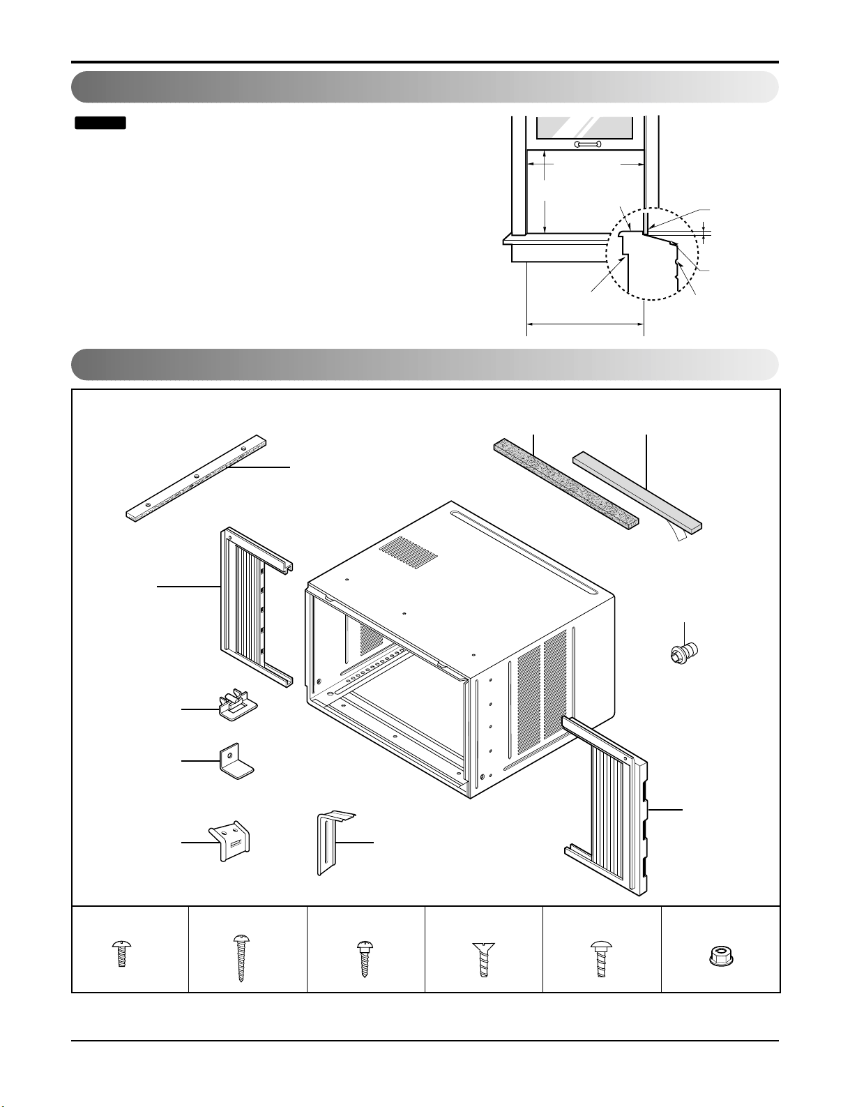
Select the Best Location
Installation Check
How to Secure the Drain Pipe
1.To prevent vibration and noise, make sure the unit is
installed securely and firmly.
2.Install the unit where the sunlight does not shine directly
on the unit.
3.The outside of the cabinet must extend outward for at
least 30cm and there should be no obstacles, such as a
fence or wall, within 50cm from the back of the cabinet
because it will prevent heat radiation of the condenser.
Restriction of outside air will greatly reduce the cooling
efficiency of the air conditioner.
CAUTION: All side louvers of the cabinet
must remain exposed to the outside of
the structure.
4.Install the unit a little slanted so the back is slightly lower
than the front (about 10~15mm). This will help force con-
densed water to the outside.
5.Install the unit from the bottom about 75~150cm above
the floor level.
The setting conditions must be checked prior to initial starting.
The following items are especially important checking points when the installation is finished.
1. Grounding wire (Green or Green and Yellow) is provided in the power cord. The green wire must be grounded.
2. Connect to a single-outlet 15A circuit.
(or 20A circuit for Electric Heater Model)
3. To avoid vibration or noise, make sure the air conditioner is installed securely.
4 Avoid placing furniture or draperies in front of the air inlet and outlet.
In humid weather, excess water may cause the BASE PAN to overflow. To drain
the water, remove the DRAIN CAP and secure the DRAIN PIPE to the rear hole of
the BASE PAN. Press the drain pipe into the hole by pushing down and away from
the fins to avoid injury.
Optional
1. Install the drain pan over the corner of the cabinet where you removed the
plug with 4 (or 2) screws.
2. Connect the drain hose to the outlet located at the bottom of the drain pan.
You can purchase the drain hose or tubing locally to satisfy your particular
needs. (Drain hose is not supplied).
3. Select the most appropriate connection from among the following figures (by
considering the hole of the unit) to fit drain pan to your own unit.
AWNING
COOLED AIR HEAT
RADIATION
75~15cm
ABOUT 10~15mm
Over 50cm
FENCE
Drain pipe
Drain cap
Fig. 4
Fig. 3
Fig. 2
DRAIN
PAN DRAIN HOSE
Fig. 1
CABINET SCREW
Figure 1
9Room Air Conditioner
Installation
Window Requirements
Installation Kits Contents
All supporting parts should be secured to firm
wood, masonry, or metal.
1. This unit is designed for installation in standard dou-
ble hung windows with actual opening widths from
26" to 41".
The top and bottom window sashes must open suffi-
ciently to allow a clear vertical opening of 18" from
the bottom of the upper sash to the window stool.
2. The stool offset (height between the stool and sill)
must be less than 1 1/4".
NOTICE
Foam-PE
(Adhesive-Backed)
Foam-PE
(Adhesive-Backed)
Type C (5) Type D (2)
Type A (14)
Carriage Bolt (2) Lock Nut (4)
Type B (7)
Foam strip
(Plain-Back)
Right frame
curtain
Window locking
bracket
Left frame
curtain
Frame guide(2)
Sill
bracket
(2)
26" to 41"
18" min Offset
Less
than 1 1/4"
Sill
Exterior
Interior wall
26" min.
(Without frame curtain)
Stool
Support bracket(2)
Drain joint pipe
Questo manuale è adatto per i seguenti modelli
4
Indice
Altri manuali LG Condizionatore d'aria

LG
LG LW1012ER Manuale utente

LG
LG ATUQ24GNLT0 Manuale utente

LG
LG T05EV5 Manuale utente

LG
LG Ceiling Cassette Manuale utente

LG
LG MULTI V TJ Series Manuale utente

LG
LG Multi Type Air Conditioner Manuale utente

LG
LG LP156HD5A Manuale utente

LG
LG LM360CE Manuale del proprietario

LG
LG WR-8030 Manuale utente

LG
LG I09AWN-NB11 Manuale utente

LG
LG LP1015WSR Manuale utente

LG
LG LPUC808FA0 Manuale utente

LG
LG LS-H126RLN1 Manuale utente

LG
LG CC18AWU Manuale utente

LG
LG ARNU183VJA2 Manuale utente

LG
LG LW1511ER Manuale utente

LG
LG PQCPA11A0E Istruzioni operative

LG
LG VM1 ZVNQ18GM1E0 Manuale utente

LG
LG LP1415GXR Manuale utente

LG
LG AS-W243C4B1 Manuale utente


