
LG DLE0442W Manuale utente

Website:http://www.LGservice.com [For U.S.A]
www.lg.ca [For Cana a]
ELECTRIC & GAS DRYER
SERVICE MANUAL
CAUTION
READ THIS MANUAL CAREFULLY TO DIAGNOSE
TROUBLES CORRECTLY BEFORE OFFERING SERVICE.
MODEL : DLE0442W DLG0452W
DLE0442S DLG0452S
DLE6942W DLG6952W
DLE5944WM DLG5955WM
DLE2544W DLG2555W
2
To avoid personal injury, disconnect power before servicing this product. If electrical power is required
for diagnosis or test purposes, disconnect the power immediately after performing the necessary checks.
!
WARNING !
WHAT TO DO IF YOU SMELL GAS:
IMPORTANT SAFETY NOTICE
The information in this service gui e is inten e for use by in ivi uals possessing a equate backgroun s
of electrical, electronic, an mechanical experience. Any attempt to repair a major appliance may result in
personal injury an property amage. The manufacturer or seller cannot be responsible for the
interpretation of this information, nor can it assume any liability in connection with its use.
RECONNECT ALL GROUNDING DEVICES
If groun ing wires, screws, straps, clips, nuts, or washers use to complete a path to groun are
remove for service, they must be returne to their original position an properly fastene .
IMPORTANT
Electrostatic Discharge (ESD)
Sensitive Electronics
ESD problems are present everywhere. ESD may damage or weaken the electronic
control assembly. The new control assembly may appear to work well after repair is
finished, but failure may occur at a later date due to ESD stress.
Use an anti-static wrist strap. Connect wrist strap to green groun connection point or unpainte
metal in the appliance.
- OR -
Touch your finger repeatedly to a green ground connection point or unpainted metal
in the appliance.
Before removing the part from its package, touch the anti-static bag to a green groun connection
point or unpainte metal in the appliance.
Avoi touching electronic parts or terminal contacts; han le electronic control assembly by e ges only.
When repackaging faile electronic control assembly in anti-static bag, observe above instructions.
■Do not try to light a match, or cigarette, or turn on
any gas or electrical appliance.
■Do not touch any electrical switches. Do not use any
phone in your building.
■Clear the room, building or area of all occupants.
■Immediately call your gas supplier from a neighbor’s
phone. Follow the gas supplier’s instructions
carefully.
■If you cannot reach your gas supplier, call the fire
department.

3
1. SPECIFICATIONS ..................................................................................................................4
2. FEATURES AND BENEFITS .................................................................................................... 5
3. INSTALLATION INSTRUCTIONS ........................................................................................... 6
4. COLUMBUS DRYER CYCLE PROCESS .................................................................................... 9
5. COMPONENT TESTING INFORMATION ..............................................................................10
6. MOTOR DIAGRAM AND SCHEMATIC..................................................................................13
7. CONTROL LAY - OUT .........................................................................................................14
8. WIRING DIAGRAM ............................................................................................................15
9. DIAGNOSTIC TEST .............................................................................................................16
9-1. TEST 1 120VAC ELECTRICAL SUPPLY..........................................................................17
9-2. TEST 2 THERMISTOR TEST --- MEASURE WITH POWER OFF .......................................18
9-3. TEST 3 MOTOR TEST ................................................................................................19
9-4. TEST 4 MOISTURE SENSOR ....................................................................................20
9-5. TEST 5 DOOR SWITCH TEST ...................................................................................21
9-6. TEST 6 HEATER SWITCH TEST - ELECTRIC TYPE...........................................................22
9-7. TEST 7 GAS VALVE TEST - GAS TYPE .........................................................................23
10. CHANGE GAS SETTING (NATURAL GAS, PROPANE GAS) ...............................................24
11. DISASSEMBLY INSTRUCTIONS .........................................................................................26
12. EXPLODED VIEW ..............................................................................................................32
12-1. CONTROL PANEL & PLATE ASSEMBLY .......................................................................32
12-2. CABINET & DOOR ASSEMBLY...................................................................................33
12-3-1. DRUM & MOTOR ASSEMBLY : ELECTRIC TYPE ........................................................34
12-3-2. DRUM & MOTOR ASSEMBLY : GAS TYPE ...............................................................35
13. REPLACEMENT PARTS LIST ................................................................................................36
CONTENTS
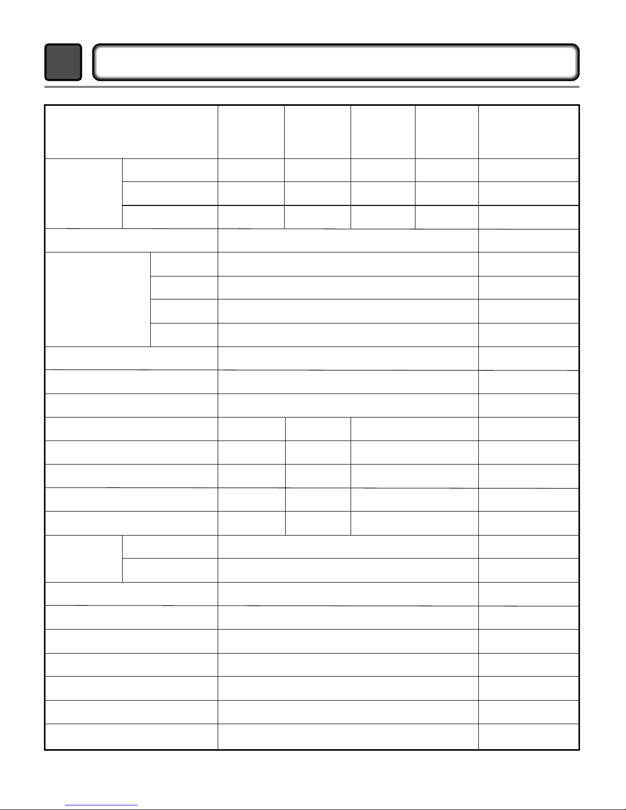
Equipped
Temperature
Moisture
Equipped
Adopted
Equipped
27" x 42
3/4" x 28 1/3"
29 1/2" x 44 3/4" x 30 3/4"
High / ow / Off
High / ow / Off
High / ow / Off
Equipped
Stainless Steel
Equipped
Sensor
55
5
126 / 144
Door Trim
Top Plate
Color
Chrome ChromeSilver
Porcelain
PorcelainPorcelain
White White
White
Spray
Titanium
120V / 240V 60Hz (26A)POWER SUPP Y
AMP
HEATER
MOTOR
55
5
999
7.3 cu.ft.
Electronic
15W (125mA)
GAS VA VE
13W (110mA) X 2
5400W (22.5A)
555
250W (4.5A)
E ECTRICITY
CONSUMPTION
White
Material &
Finishes
D E0442W
D E5944WM
D G0452W
D G5955WM
D E2544W
D G2555W
D E0442S
D G0452S
D E6942W
D G6952W
ITEM
Child lock
Reversible Door
Interior ight
Product (WXHXD)
Packing (WXHXD)
Audible End of Cycle Beeper
Dryer Rack
Drum
No. of Dry evels
No. of Dry Option
No. of Programs
DRUM CAPACITY
CONTRO TYPE
No. of Temperature Controls
Weight (lbs): Net / Gross
AC 120V
( GAS TYPE)
AC 240V
( E ECTRIC TYPE)
Thermistor
Electro sensor
AC 120V
AC 120V
REMARK
4
SPECIFICATIONS
1
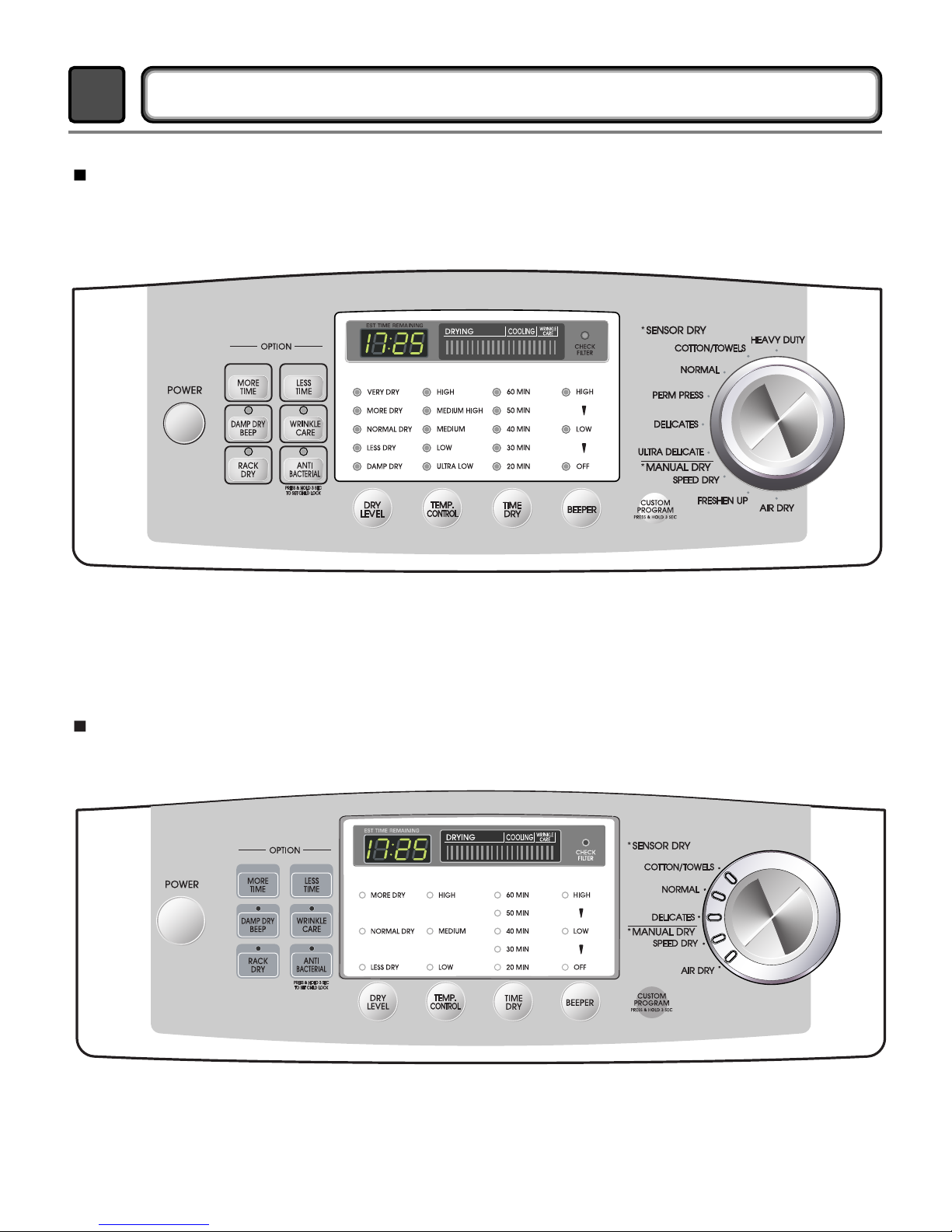
5
FEATURES AND BENEFITS
2
DLE0442W/DLG0452W/DLE0442S/DLG0452S/DLE6942W/DLG6952W/DLE5944WM/
DLG5955WM
DLE2544W/DLG2555W
6
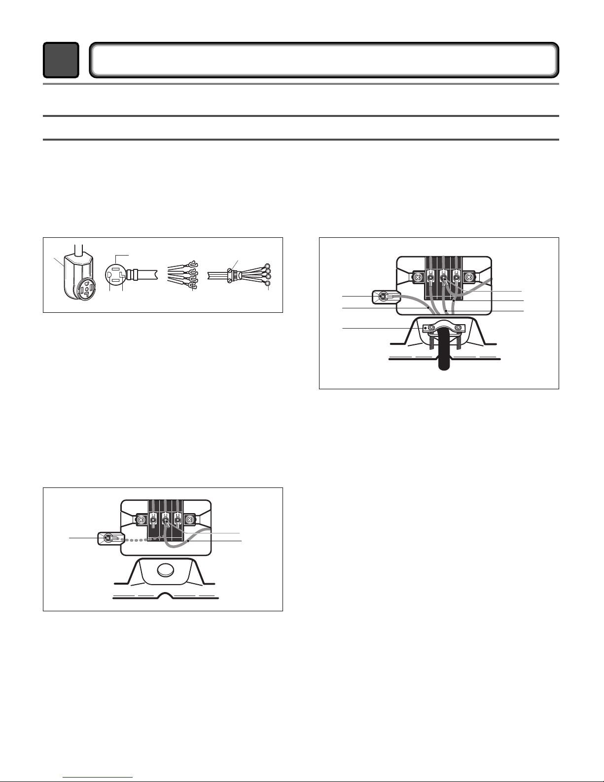
3-1. POWER CORD
INSTALLATION INSTRUCTIONS
3
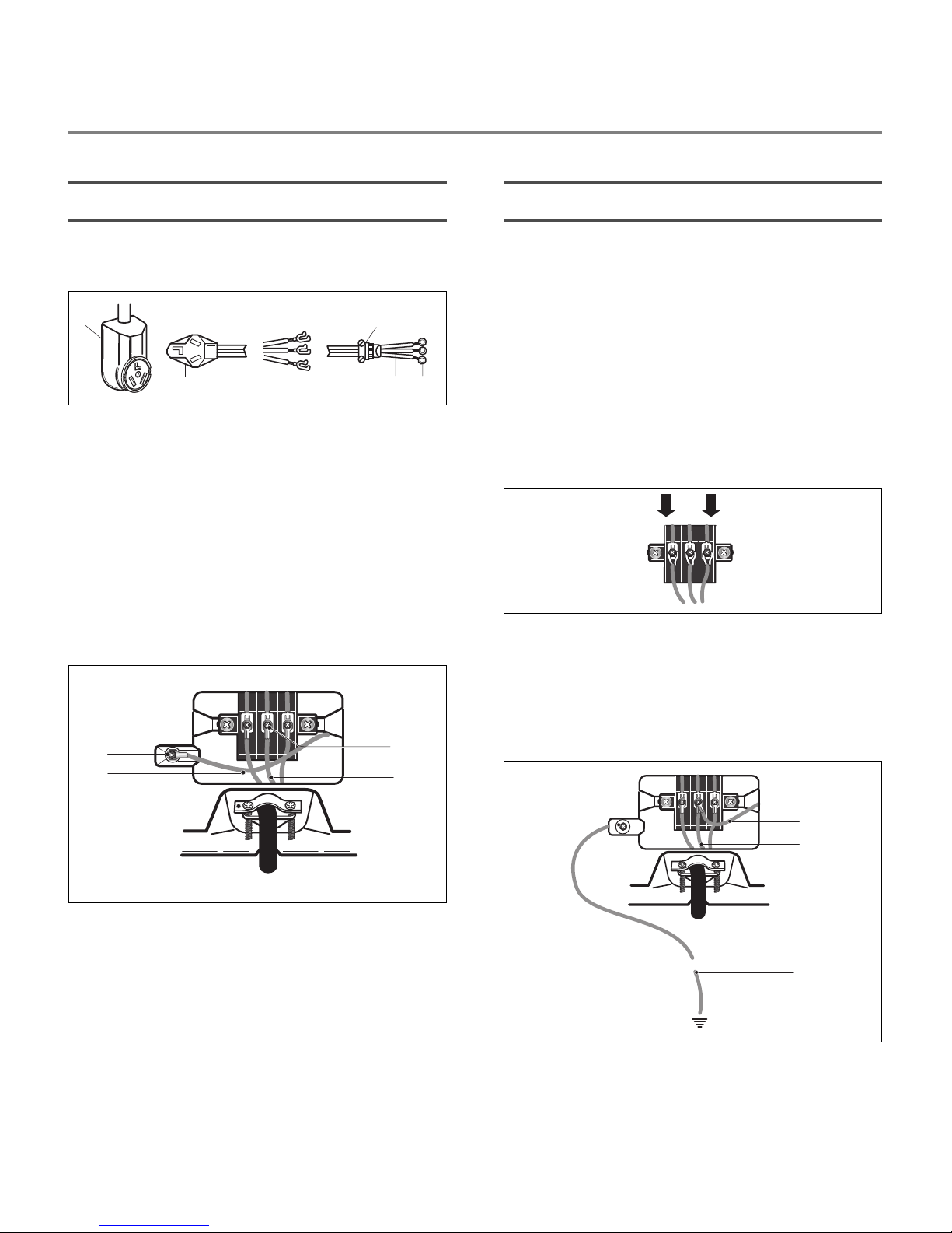
1) 4-wire connection
1. External ground connector - Dotted line shows
position of NEUTRAL ground wire before being
moved to center terminal block screw
2. Center silver-colored terminal block screw
3. Green wire of harness
1. External ground connector
2. Green or bare copper wire of power supply cord
3. 3/4 in. (1.9 cm) UL-listed strain relief
4. Center silver-colored terminal block screw
5. Neutral grounding wire (green)
6. Neutral wire (white)
5. Connect the other wires to outer terminal block
screws. Tighten screws.
6. Tighten strain relief screws.
7. Insert tab of terminal block cover into slot of ryer
rear panel Secure cover with hol - own screw.
3. Connect groun wire (green or bare) of power
supply cable to external groun con uctor screw.
Tighten screw.
4. Connect neutral wire (white or center wire) of
power supply cor to the center, silver colore
terminal screw of the terminal block.
1. 4-wire receptacle (NEMA type 14-30R)
2. 4-prong plug
3. Ground prong
4. Neutral prong
5. Spade terminals with upturned ends
6. 3/4 in. (1.9 cm) UL approved strain relief
7. Ring terminals
1. Remove center terminal block screw.
2. Remove appliance groun wire (green) from
external groun connector screw. Fasten it un er
center, silver colore terminal block screw.
IMPORTANT: A 4-wire connection is
required for mobile
homes and where local
codes do not permit the
use of 3 wire connections.
12
3 4 5 7
6
6
5
3
2
14
3
12
7
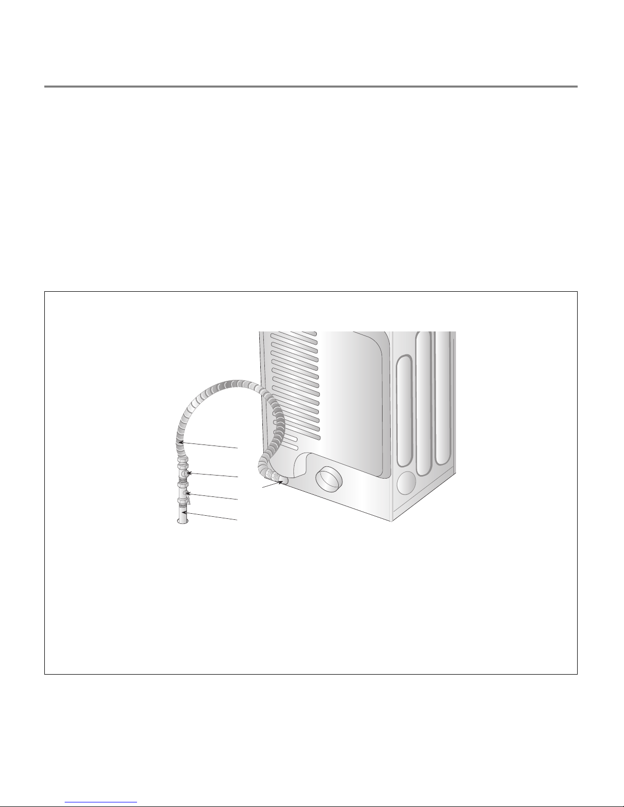
2) 3-wire connection
Use where local codes permit connecting
cabinet-ground conductor to neutral wire.
1. Remove center terminal block screw.
2. Remove appliance groun wire (green) from
external groun connector screw. Connect
appliance groun wire an the neutral wire (white
or center wire) of power supply cor /cable un er
center, silver colore terminal block screw.
Tighten screw.
3. Connect the other wires to outer terminal block
screws. Tighten screws.
Use where local codes permit connecting
cabinet-ground conductor to neutral wire.
3) Optional 3-wire connection
1. Loosen or remove center terminal block screw.
2.
Connect neutral wire (white or center wire) of
power supply cor to the center, silver colore
terminal screw of the terminal block. Tighten screw.
1. External ground connector
2. Neutral grounding wire (green)
3. Center silver-colored terminal block screw
4. Neutral wire (white or center wire)
5. 3/4 in. (1.9 cm) UL-listed strain relief
3. Connect the other wires to outer terminal block
screws. Tighten screws.
4. Tighten strain relief screws.
5. Insert tab of terminal block cover into slot of ryer
rear panel. Secure cover with hol - own screw.
4. Tighten strain relief screws.
5. Insert tab of terminal block cover into slot of ryer
rear panel. Secure cover with hol - own screw.
6. Connect a separate copper groun wire from the
external groun connector screw to an a equate
groun .
1. External ground connector
2. Neutral grounding wire (green)
3. Neutral wire (white or center wire)
4.
Grounding path determined by a qualified electrician
1. 3-wire receptacle (NEMA type 10-30R)
2. 3-wire plug
3. Neutral prong
4. Spade terminals with up turned ends
5. 3/4 in. (1.9 cm) UL approved strain relief
6. Ring terminals
7. Neutral (white or center wire)
3
12
4
4
2
5
13
4
76
5
2
3
1
8
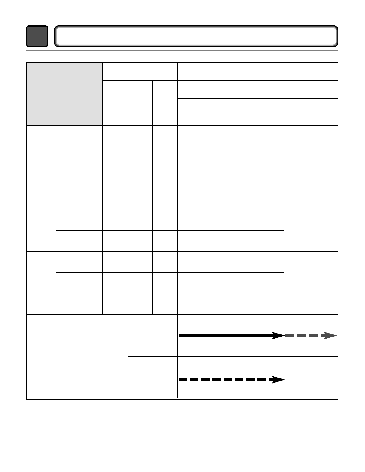
3-2. Connect Gas Supply Pipe (Gas Dryer ONL )
2
3
5
1
4
1. Make certain your ryer is equippe for use with the
type of gas in your laun ry room. Dryer is equippe
at the factory for Natural Gas with a 3/8” N.P.T. gas
connection.
2. Remove the shipping cap from the gas connection
at the rear of the ryer. Make sure you o not
amage the pipe threa when removing the cap.
3. Connect to gas supply pipe using a new flexible
stainless steel connector.
4. Tighten all connections securely. Turn on gas an
check all pipe connections (internal & external) for
gas leaks with a non-corrosive leak etection flui .
5. For L.P. (Liquefie Petroleum) gas connection, refer
to section on Gas Requirements.
For further assistance, refer to section on Gas Requirements.
1 New Stainless Steel Flexible Connector - Use
only if allowed by local codes (Use Design
A.G.A. Certified Connector)
2 1/8” N.P.T. Pipe Plug
(for checking inlet gas pressure)
3 Equipment Shut-Off Valve-Installed within 6’
(1.8 m) of dryer
4 Black Iron Pipe
Shorter than 20’ (6.1 m) - Use 3/8” pipe
Longer than 20’ (6.1 m) - Use 1/2” pipe
5 3/8” N.P.T. Gas Connection
9
Time
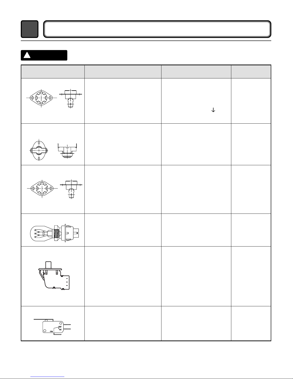
COLUMBUS DRYER CYCLE PROCESS
4
Cycle
Heavy Duty
3Hr
3Hr
Off Time: 6min
On Time: 10sec
Temperature Control for each cycle
High
Me ium
High
Me ium
Low
Low
Extra
low
(High)
(Me ium
High)
Cotton/
Towel
Normal
Perm.
Permanent
Press
Delicate
Ultra
Delicate
Spee ry
Freshen Up
Air ry
-
(Normal)
(Normal)
(Normal)
(Normal)
(Normal)
(Normal)
-
-
-
54min Saturation
Saturation
Saturation
Saturation
Saturation
Saturation
Saturation
Saturation
55min
41min
36min
32min
34min
25min
20
min
30
min
(5min)
(5min)
(5min)
(5min)
(5min)
(5min)
(5min)
(5min)
N/A
70±5°C
66±5°C
62±5°C
55±5°C
55±5°C
45±5°C
(70±5°C)
(66±5°C)
No
heater
47±5°C
47±5°C
47±5°C
47±5°C
38±5°C
38±5°C
(47±5°C)
(47±5°C)
N/A
Saturation
Load
Sense
Dry *
Manual
Dry **
Default
Drying
Electro-
sensor
Temp-
Control
Default
time
Temp-
Control **
Cooling Wrinkle care
Conditions of operation and termination
Temp-
erature
Dry
Level
Display
time
Motor
Heater
* Sense ry : “Dry Level” is set by users.
** Manual ry : “Temperature control” is set by users.
Default settings can be a juste by users.
10
When checking the Component, be sure to turn the power off, and do voltage discharge sufficiently.
COMPONENT TESTING INFORMATION
5
!
CAUTION
Component Test Procedure Check result Remark
1. Thermal cut off
• Check Top Marking :
N130
Measure resistance of terminal
to terminal
Open at 284 ±12°F
(140 ±7°C)
Auto reset -31°F (-35°C)
Same shape as Outlet Thermostat.
If thermal fuse is open must
be replace
Resistance value ≒∞
Continuity (250°F ) < 1Ω
• Heater case-
Safety
• Electric type
2. Hi limit Thermostat
(Auto reset)
Measure resistance of terminal
to terminal
Open at 257 ±9°F
(125 ±5°C)
Close at 221 ±9°F
(105 ±5°C)
Resistance value ≒∞
Resistance value < 5Ω
• Heater case -
Hi limit
• Electric type
3. Outlet Thermostat
( Auto reset)
• Check Top Marking :
N85
Measure resistance of terminal
to terminal
Open at 185 ±9°F
(85 ±5°C)
Close at 149 ±9°F
(65 ±5°C)
Same shape as Thermal cut off.
Resistance value ≒∞
Resistance value < 5Ω
• Blow housing -
Safety
• Electric type
4. Lamp hol er Measure resistance of terminal
to terminal
Resistance value :
80Ω ~ 100Ω
6. I ler switch Measure resistance of the
following terminal :
“COM - NC”
1. lever open
Resistance value < 1Ω
2. Lever push (close)
Resistance value ≒∞
5. Door switch Measure resistance of the
following terminal
1) Door switch knob : open
Terminal : “COM” - “NC” (1-3)
Terminal : “COM” - “NO” (1-2)
2) Door switch push : push
Terminal : “COM” - “NC” (1-3)
Terminal : “COM” - “NO” (1-2)
Resistance value < 1Ω
Resistance value ≒∞
Resistance value ≒∞
Resistance value < 1Ω
The state that
Knob is
presse is
opposite to
Open
con ition.
Altri manuali per DLE0442W
5
Questo manuale è adatto per i seguenti modelli
9
Indice
Altri manuali LG Asciugatrice

LG
LG RC9055APZ Manuale utente

LG
LG DF22BV2B Manuale utente

LG
LG SteamDryer LSDG389VS Manuale utente

LG
LG DLE2250 Series Manuale utente

LG
LG DLGX5781 Manuale utente

LG
LG DLEY1701VE Manuale utente

LG
LG DLEY1701VE Manuale utente

LG
LG DLE3180 serirs Manuale utente

LG
LG Dle1501 series Manuale utente

LG
LG DLE0332W Manuale utente

LG
LG DLGX89 1 Series Manuale utente

LG
LG FDV309W Manuale utente

LG
LG DLE2140W Manuale utente

LG
LG GDL1329CGS3 Manuale utente

LG
LG RC9055AP2Z Manuale utente

LG
LG RC9011G2 Manuale utente

LG
LG Tromm DLEX8377NM Manuale utente

LG
LG DLEX5170 Series Manuale utente

LG
LG DLGX3571 series Manuale utente

LG
LG DLEX3885 Series Manuale utente


