LG Flatron 795FT Plus (FB795E-UA) Manuale utente

COLOR MONITOR
SERVICE MANUAL
Website:http://biz.LGservice.com
E-mail:http://www.LGEservice.com/techsup.html
CAUTION
BEFORE SERVICING THE UNIT,
READ THE SAFETY PRECAUTIONS IN THIS MANUAL.
MODEL: ( ) 795FT Plus (FB795E-UA),
CHASSIS NO. : CA-103
FACTORY MODEL: FB795E
*( ) ID LABEL Model No.
OSD SET
795FT Plus (FB795E-UP)

1. PICTURE TUBE
Size : 17 inch (Flat Slot Mask)
DefIection Angle : 90°
Neck Diameter : 29.1 mm
Phosphor : P22
Slot Pitch : 0.24 mm
Face Treatment : W-ARASC (Anti-Reflective and
Anti-Static Coating),
Internal Anti-Glare
2. SIGNAL
2-1. Horizontal & Vertical Sync
1) Input Voltage Level: Low= ≤0.8V, High= ≥2.1V
2) Sync Polarity : Positive or Negative
2-2. Video Input Signal
1) Voltage Level : 0~0.7 Vp-p
a) Color 0, 0 : 0 Vp-p
b) Color 7, 0 : 0.467 Vp-p
c) Color 15, 0 : 0.7 Vp-p
2) Input Impedance : 75 Ω
3) Video Color : R, G, B Analog
4) Signal Format : Refer to the Timing Chart
2-3. Signal Connector
15 Pin D-Sub Connector
2-4. Scanning Frequency
Horizontal : 30~96 kHz
Vertical : 50~160 Hz
3. POWER SUPPLY
AC 100~240V, 50/60HZ, 2.5A Max.(Free Voltage)
AC 200~240V, 50Hz, 1.5A Max.(PFC version)
3-2. Power Consumption
4. DISPLAY AREA
4-1. Active Video Area :
• Max Image Size - 325.4 x 244.1mm (12.91" x 9.61")
• Preset Image Size - 310 x 230 mm (12.20" x 9.06")
4-2. Display Color : Full Colors
4-3. Display Resolution : 1600 Dots x 1200Lines
4-4. Video Bandwidth : 203MHz
5. ENVIRONMENT
5-1. Operating Temperature: 10°C~35°C (50°F~95°F)
(Ambient)
5-2. Relative Humidity : 8%~80%
(Non-condensing)
5-3. Altitude : 10,000 ft
6. DIMENSIONS (with TILT/SWIVEL)
Width : 415.0 mm (16.34")
Depth : 439.0 mm (17.28")
Height : 435.0 mm (17.13")
7. WEIGHT (with TILT/SWIVEL)
Net Weight : 19.2 kg (42.33 lbs)
Gross Weight : 22.7 kg (50.05 lbs)
8. USB Specifications (Option)
USB Standard :
Rev. 1.0 complied self-powered hub
Downstream power supply
: 500mA for each (MAX)
Communication speed : 12 Mbps (Full), 1.5 Mbps (Low)
USB port : 1 Upstream port
4 Downstream ports
CONTENTS
SPECIFICATIONS
- 2 -
SPECIFICATIONS ................................................... 2
SAFETY PRECAUTIONS ........................................ 3
TIMING CHART ....................................................... 4
OPERATING INSTRUCTIONS ................................ 5
CONTROL LOCATIONS ......................................... 7
WIRING DIAGRAM ................................................. 8
DISASSEMBLY ....................................................... 9
BLOCK DIAGRAM ................................................. 12
DESCRIPTION OF BLOCK DIAGRAM...................13
ADJUSTMENT ...................................................... 15
TROUBLESHOOTING GUIDE .............................. 17
EXPLODED VIEW.................................................. 24
REPLACEMENT PARTS LIST .............................. 26
PIN CONFIGURATION .......................................... 35
SCHEMATIC DIAGRAM......................................... 39
PRINTED CIRCUIT BOARD................................... 41
MODE
MAX
NORMAL (ON)
STAND-BY
SUSPEND
OFF
H/V SYNC
ON/ON
OFF/ON
ON/OFF
OFF/OFF
POWER CONSUMPTION (USB)
less than 110W (130W)
less than 84W (104W)
less than 8W (30W)
less than 8W (30W)
less than 3W (20W)
LED COLOR
GREEN
GREEN
ORANGE
ORANGE

SAFETY PRECAUTIONS
- 3 -
SAFETY-RELATED COMPONENT WARNING!
There are special components used in this color monitor
which are important for safety. These parts are marked
on the schematic diagram and the replacement
parts list. It is essential that these critical parts should be
replaced with the manufacturer's specified parts to
prevent X-radiation, shock, fire, or other hazards. Do not
modify the original design without obtaining written
permission from LG or you will void the original parts and
labor guarantee.
CAUTION:
No modification of any circuit should be
attempted.
Service work should be performed only after
you are thoroughly familiar with all of the
following safety checks and servicing
guidelines.
SAFETY CHECK
Care should be taken while servicing this color monitor
because of the high voltage used in the deflection circuits.
These voltages are exposed in such areas as the
associated flyback and yoke circuits.
FIRE & SHOCK HAZARD
An isolation transformer must be inserted between the
color monitor and AC power line before servicing the
chassis.
• In servicing, attention must be paid to the original lead
dress specially in the high voltage circuit. If a short
circuit is found, replace all parts which have been
overheated as a result of the short circuit.
• All the protective devices must be reinstalled per the
original design.
• Soldering must be inspected for the cold solder joints,
frayed leads, damaged insulation, solder splashes, or
the sharp points. Be sure to remove all foreign
materials.
IMPLOSION PROTECTION
All used display tubes are equipped with an integral
implosion protection system, but care should be taken to
avoid damage and scratching during installation. Use only
same type display tubes.
X-RADIATION
The only potential source of X-radiation is the picture tube.
However, when the high voltage circuitry is operating
properly there is no possibility of an X-radiation problem.
The basic precaution which must be exercised is keep the
high voltage at the factory recommended level; the normal
high voltage is about 26kV. The following steps describe
how to measure the high voltage and how to prevent X-
radiation.
Note : It is important to use an accurate high voltage
meter calibrated periodically.
• To measure the high voltage, use a high impedance
high voltage meter, connect (–) to chassis and (+) to
the CDT anode cap.
• Set the brightness control to maximum point at full
white pattern.
• Measure the high voltage. The high voltage meter
should be indicated at the factory recommended level.
• If the meter indication exceeds the maximum level,
immediate service is required to prevent the possibility
of premature component failure.
• To prevent X-radiation possibility, it is essential to use
the specified picture tube.
CAUTION:
Please use only a plastic screwdriver to protect yourself
from shock hazard during service operation.

TIMING CHART
- 4 -
VIDEO
SYNC D
A
EF
BC
kHz
µs
µs
µs
µs
µs
µs
Hz
ms
ms
ms
ms
ms
ms
MODE 1
–
43.269
23.112
17.778
5.334
1.556
1.556
2.222
–
85.008
11.763
11.093
0.670
0.023
0.069
0.578
640
X
480
85Hz
Yes
MODE 2
+
53.674
18.631
14.222
4.409
0.569
1.138
2.702
+
85.061
11.756
11.178
0.578
0.019
0.056
0.503
800
X
600
85Hz
Yes
MODE 3
+
68.677
14.561
10.836
3.725
0.508
1.016
2.201
+
84.997
11.765
11.183
0.582
0.015
0.044
0.523
1024
X
768
85Hz
Yes
MARK
A
B
C
D
E
F
A
B
C
D
E
F
MODE
FACTORY PRESET MODE
Resolution
Recall
H
O
R
I
Z
O
N
T
A
L
V
E
R
T
I
C
A
L
Sync Polarity
Frequency
Total Period
Video Active Time
Blanking Time
Front Porch
Sync Duration
Back Porch
Sync Polarity
Frequency
Total Period
Video Active Time
Blanking Time
Front Porch
Sync Duration
Back Porch
MODE 4
+
91.146
10.971
8.127
2.844
0.406
1.016
1.422
+
85.024
11.762
11.235
0.527
0.011
0.033
0.483
1280
X
1024
85Hz
Yes
VESA

OPERATING INSTRUCTIONS
- 5 -
REAR VIEWFRONT VIEW
Front Control Panel
OSD SET
See Front Control Panel Power Button
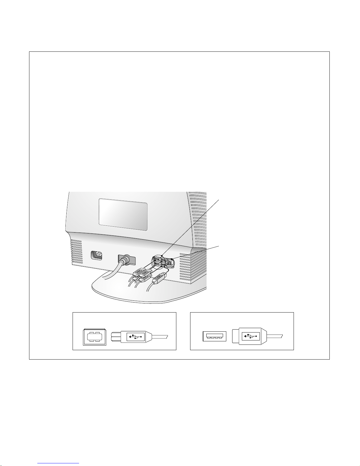
USB Upstream port
USB Downstream ports
D-Sub Signal Connector
AC Power
Socket
1. Power ON/OFF Button
This button is used to turn the monitor ON and
OFF.
2. Power Indicator
This indicator lights up green when the monitor
operates normally; in DPMS (Energy Saving)
mode, -stand-by, suspend, or power off mode - it
color changes to orange.
3. SET Buttons
Use this button to enter a selection in the onscreen
display.
4. OSD Select/adjust Button
Use these button to choose or adjust items in the
on screen display.
5. OSD Button
Use this button to enter or exit the on screen
display.
OSD SET
12345
Press the buttons to display the menu and then the
buttons to adjust the settings. To save all changes, press
the OSD button. The Brightness and Contrast functions
are also available in the On Screen Display (OSD) menu.
<Shortcut Keys>
•Brightness and Contrast can be
adjusted directly withou entering the
On Screen Display (OSD) system.
100
100

Universal Serial Bus
- 6 -
USB connection (Option)
(1) Connect the upstream port of the monitor to the downstream port of the USB
compliant PC or another hub using the USB cable.
(2) Connect the USB compliant peripherals to the downstream ports the monitor.
*USB(Universal Serial Bus) is supported WINDOWS98 and Higher.
Making use of USB (Universal Serial Bus)*
USB(Universal Serial Bus) is an innovation in connecting your different desktop peripherals conveniently to your
computer. By using the USB, you will be able to connect your mouse, keyboard, printer, and other peripherals to
your monitor instead of having to connect them to your computer. This will give you greater flexibility in setting
up your system. USB allows you to connect chain up to 120 devices on a single USB port, and you can “hot”
plug (attach them while the computer is running) or unplug them while maintaining Plug and Plug auto detection
and configuration. This monitor has an integrated self-powered USB hub, allowing up to 4 other USB devices to
be attached it.
USB Downstream Ports
Connect the cables from USB compliant
peripherals-such as keyboard, mouse,
printer, scanner, etc.
USB Upstream Port
To USB downstream port
of the USB compliant PC
or another hub cable
USB Upstream connector USB Downstream connector

CONTROL LOCATIONS
- 7 -
VR701
: High Voltage Adjustment
VR901: B Adjustment
(190V Line)
+

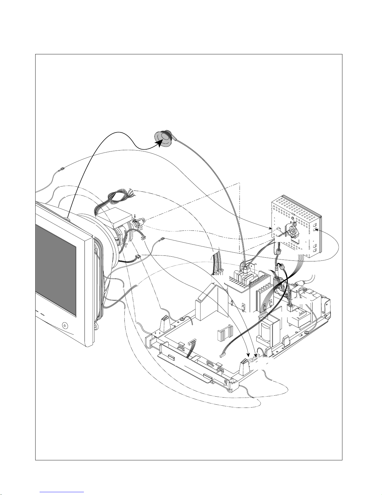
WIRING DIAGRAM
- 8 -
DY-Pin
P702 P901
P520
P102
P302
P303
P701
P401
Degaussing
Coil
P451
P453
DYAssembly Screw
P921
P303
Anode Cap

DISASSEMBLY
- 9 -
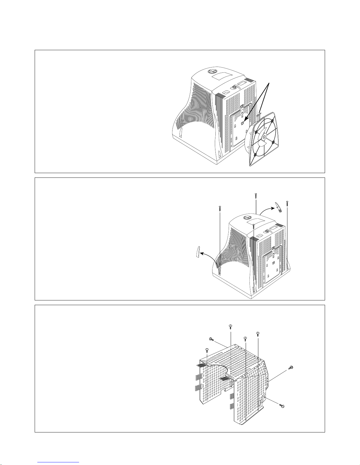
3. TOP SHIELD REMOVAL
1) Remove seven screws (a).
2. BACK COVER REMOVAL
1) Remove four screws (a) from the Back Cover.
2) Slide the Back Cover away from the Front Cabinet
of the monitor.
1. TILT/SWIVEL REMOVAL
1) Set the monitor face downward.
2) Pressing the latch (a), carefully remove
the Tilt/Swivel by pulling it upward.
(a)
(a)
(b)
(b)
(b) (b)
(a)
(a)
(a)
(a)
(a)
(a)
(a)
(a)

- 10 -
4. TOTAL CHASSIS ASSEMBLY REMOVAL
1) Disconnector the CDT Earth Pin(a).
2) Remove four screws (a).
3) Disconnect P901 (Degaussing pin), P701 (DY pin), P451, P453 from the Main PCB.
4) Disconnect P301, P302, P303 from the Video PCB.
5) Remove the DY Assembly Screw (c).
6) Carefully separate the CDT Board Assembly from the CDT neck.
7) Discharge the remaining static electricity by shorting between the Anode Cap and the CDT ground.
8) Disconnect the Anode Cap from the CDT.
9) Remove the Total Chassis Assembly from the Main PCB Ass’y and Video PCB Ass’y.
DY-Pin
P901
P451
P302
P303
P301
Degaussing
Coil
(b)
(b)
(b)
(b)
(a) (a)
(c)(d)
P453
P702
P701
P401
Anode Cap
DYAssembly Screw
Questo manuale è adatto per i seguenti modelli
4
Indice
Altri manuali LG Monitor

LG
LG UltraGear 32GN650-B.ATID Manuale utente

LG
LG 32UL750-W.AEU Manuale utente

LG
LG 47WX50MF-B Manuale utente

LG
LG UltraGear 24GN650 Manuale utente

LG
LG W2262TQ Manuale utente

LG
LG 34BL650 Manuale utente

LG
LG Flatron M198WA Manuale utente

LG
LG ULTRAGEAR 27GP850P-B Manuale utente

LG
LG 60PJ101C Manuale utente

LG
LG M5203C Manuale utente

LG
LG E1960S Manuale utente

LG
LG UltraGear 45GR95QE Manuale utente

LG
LG Flatron M228WA Manuale utente

LG
LG E1942CW Manuale utente

LG
LG 32MA70HY Manuale utente

LG
LG FLATRON L3000A Manuale utente

LG
LG 22MP57D Manuale utente

LG
LG 20EN33S Manuale utente

LG
LG Flatron L1718S Manuale utente

LG
LG 34BK95U Manuale utente