
LG Flatron L1720B Manuale utente

COLOR MONITOR
SERVICE MANUAL
CAUTION
BEFORE SERVICING THE UNIT,
READ THE SAFETY PRECAUTIONS IN THIS MANUAL.
CHASSIS NO. : CL-43
MODEL: L1720B
(L1720BL-AL**R)
1. LCD CHARACTERISTICS
Type : TFT SXGA LCD
Size : 17 inch
Pixel Pitch : 0.264 (H) x 0.264 (V)
Color Depth : 16.2M colors
Electrical Interface : LVDS
Surface Treatment : Hard-coating(3H)
Operating Mode : Normally White
Backlight Unit : Top/Bottom edge side 4-CCFL
(Cold Cathode Fluorescent Lamp)
2. OPTICAL CHARACTERISTICS
2-1. Viewing Angle by Contrast Ratio
≥
10
Left : -60° min., -70°(Typ) Right : +60° min., +70°(Typ)
Top :+50° min., +60°(Typ) Bottom : -45°min., -60°(Typ)
2-2. Luminance : 200(min), 250(Typ)
2-3. Contrast Ratio : 300(min), 400(Typ)
3. SIGNAL (Refer to the Timing Chart)
3-1. Sync Signal
• Type : Separate Sync,
SOG (Sync On Green)
Composite Sync
3-2. Video Input Signal
1) Type : R, G, B Analog
2) Voltage Level : 0~0.71 V
a) Color 0, 0 : 0 Vp-p
b) Color 7, 0 : 0.467 Vp-p
c) Color 15, 0 : 0.714 Vp-p
3) Input Impedance : 75 Ω
3-3. Operating Frequency
Horizontal : 30 ~ 83kHz
Vertical : 56 ~ 75Hz
4
. Max. Resolution
Analog : 1280 x 1024 / 75Hz
5. POWER SUPPLY
5-1. Power
: AC 100-240V~, 50/60Hz , 1.0A
5-2. Power Consumption
6. ENVIRONMENT
6-1. Operating Temperature: 10°C~35°C (50°F~95°F)
(Ambient)
6-2. Relative Humidity : 10%~80%
(Non-condensing)
6-3. MTBF : 50,000 Hours(Min)
7. DIMENSIONS (with TILT/SWIVEL)
FullUp Position
Width : 394 mm (15.51'')
Depth : 232 mm (9.13'')
Height : 379 mm (14.92'')
Folded Position
Width : 394mm (15.51'')
Depth : 127mm (9.13'')
Height : 412mm (14.92'')
8. WEIGHT (with TILT/SWIVEL)
Net. Weight : 4.5 kg (9.92 lbs)
Gross Weight : 7.6 kg (16.76 lbs)
CONTENTS
SPECIFICATIONS
- 2 -
SPECIFICATIONS ................................................... 2
PRECAUTIONS ....................................................... 3
TIMING CHART ....................................................... 4
OPERATING INSTRUCTIONS ................................ 5
WIRING DIAGRAM ................................................. 6
BLOCK DIAGRAM ................................................... 7
DESCRIPTION OF BLOCK DIAGRAM.....................8
ADJUSTMENT ...................................................... 10
TROUBLESHOOTING GUIDE .............................. 11
PRINTED CIRCUIT BOARD................................... 15
EXPLODED VIEW...................................................17
REPLACEMENT PARTS LIST ...............................19
SCHEMATIC DIAGRAM......................................... 22
MODE
POWER ON (NORMAL)
STAND-BY
SUSPEND
DPMS OFF
H/V SYNC
ON/ON
OFF/ON
ON/OFF
OFF/OFF
POWER CONSUMPTION
less than 40 W
less than 2 W
less than 2 W
less than 2 W
LED COLOR
BLUE
AMBER
AMBER
AMBER
VIDEO
ACTIVE
OFF
OFF
OFF

- 3 -
WARNING FOR THE SAFETY-RELATED COMPONENT.
• There are some special components used in LCD
monitor that are important for safety. These parts are
marked on the schematic diagram and the
replacement parts list. It is essential that these critical
parts should be replaced with the manufacturer’s
specified parts to prevent electric shock, fire or other
hazard.
• Do not modify original design without obtaining written
permission from manufacturer or you will void the
original parts and labor guarantee.
TAKE CARE DURING HANDLING THE LCD MODULE
WITH BACKLIGHT UNIT.
• Must mount the module using mounting holes arranged
in four corners.
• Do not press on the panel, edge of the frame strongly
or electric shock as this will result in damage to the
screen.
• Do not scratch or press on the panel with any sharp
objects, such as pencil or pen as this may result in
damage to the panel.
• Protect the module from the ESD as it may damage the
electronic circuit (C-MOS).
• Make certain that treatment person’s body are
grounded through wrist band.
• Do not leave the module in high temperature and in
areas of high humidity for a long time.
• The module not be exposed to the direct sunlight.
• Avoid contact with water as it may a short circuit within
the module.
• If the surface of panel become dirty, please wipe it off
with a softmaterial. (Cleaning with a dirty or rough cloth
may damage the panel.)
WARNING
BE CAREFUL ELECTRIC SHOCK !
• If you want to replace with the new backlight (CCFL) or
inverter circuit, must disconnect the AC adapter
because high voltage appears at inverter circuit about
650Vrms.
• Handle with care wires or connectors of the inverter
circuit. If the wires are pressed cause short and may
burn or take fire.
PRECAUTION
CAUTION
Please use only a plastic screwdriver to protect yourself
from shock hazard during service operation.

TIMING CHART
- 4 -
VIDEO
SYNC
B
D
CFE
A
<< Dot Clock (MHz), Horizontal Frequency (kHz), Vertical Frequency (Hz), Horizontal etc... (µs), Vertical etc... (ms) >>
H + 31.469 800 640 16 96 48
V–70.8Hz 449 350 37 2 60
H–31.469 840 640 16 96 48
V–59.94 525 480 10 2 33
H–37.5 840 640 16 64 120
V–75 500 480 1 3 16
H–31.468 900 720 18 108 54
V + 70.09 449 400 12 2 35
H + 37.879 1056 800 40 128 88
V + 60.317 628 600 1 4 23
H + 46.875 1056 800 16 80 160
V + 75.0 625 600 1 3 21
H+/–49.725 1152 832 32 64 224
V+/–74.55 667 624 1 3 39
H–48.363 1344 1024 24 136 160
V–60.0 806 768 3 6 29
H–60.123 1312 1024 16 96 176
V–75.029 800 768 1 3 28
H+/–68.681 1456 1152 32 128 144
V+/–75.062 915 870 3 3 39
H+/–61.805 1504 1152 18 134 200
V+/–65.96 937 900 2 4 31
H + 63.981 1688 1280 48 112 248
V + 60.02 1066 1024 1 3 38
H + 79.976 1688 1280 16 144 248
V + 75.035 1066 1024 1 3 38
Mode H/V
Sort
1
2
3
4
5
6
7
8
9
10
11
12
13
25.175
28.321
25.175
31.5
40.0
49.5
57.283
65.0
78.75
100.0
92.978
108.0
135.0
640x350
70Hz
640x480
60Hz
640x480
75Hz
720x400
70Hz
800x600
60Hz
800x600
75Hz
832x624
75Hz
1024x768
60Hz
1024x768
75Hz
1152x870
75Hz
1152x900
65Hz
1280x1024
60Hz
1280x1024
75Hz
Sync
Polarity Frequency
Dot
Clock Total Period
(E)
Video Active Time
(A)
Sync Duration
(D)
Back Porch
(F)
Front Porch
(C)
Resolution

- 5 -
OPERATING INSTRUCTIONS
FRONT VIEW REAR VIEW
Front Control Panel
1. Power Button
Use this button to turn the display on or off.
<Power (DPMS) Indicator>
This Indicator lights up blue when the display
operates normally. If the display is in DPM (Energy
Saving) mode, this indicator color changes to
amber.
2. Button
Use these buttons to choose or adjust items in the
On Screen Display.
3. Menu Button
Use this button to enter or exit the On Screen
Display.
4.
AUTO/SELECT Button
Use this button to enter a selection in the On
Screen Display.
When adjusting your display settings, always
press the AUTO/SELECT button before entering
the On Screen Display(OSD). This will
automatically adjust your display image to the
ideal settings for the current screen resolution
size (display mode).
The best display mode is 1024x768/60Hz.
See front control panel
D-sub Connect
Power Connect
143 2
This function optimizes the brightness, contrast or
color value to the surrounding conditions and settings
and enables you to enjoy the most suitable picture by
adjusting the surroundings (DAY/NIGHT/USER
MODE).
•
TEXT: For viewing letters
•
MOVIE: For viewing movies
•
PHOTO: For viewing pictures or the photographs
•
USER MODE: This function memorizes the
manual adjustment -Brightness, Contrast and
Color value on the On Screen Display.
100
100
Bring up Contrast and Brightness adjustment.
:

- 6 -
WIRING DIAGRAM
J707
J702
CN1
CN2
CN4 CN5
CN3
Connector Ass’y :
P/N: 6631T11016C
Connector Ass’y :
P/N: 6631T20024C
Connector Ass’y :
P/N: 6631T20008G
Connector Ass’y :
P/N: 6631T20023A

- 7 -
D-SUB
MST9111
including
(ADC/LVDS/SCALER )
MTV312
Micom
LCD Module
R,G,B
differential
LVDS
(Low Voltage
Differential Signaling)
LIPS
5V
5V
5V
AC Input
3.3V
Reg. 2.5V
Reg.
5V 5V
R,G,B, H/V Sync
3.3V 2.5V
3.3V
2.5V
BLOCK DIAGRAM

- 8 -
DESCRIPTION OF BLOCK DIAGRAM
1. Video Controller Part & Display Data Transmitter Part.(MST9111)
This part amplifies the level of video signal for the digital conversion and
converts from the analog video signal to the digital video signal using a pixel clock.
The pixel clock for each mode is generated by the PLL.
The range of the pixel clock is from 25MHz to 135MHz.
This part consists of the Scaler.
The Scaler gets the video signal converted analog to digital,
interpolates input to 1280 x 1024 resolution signal and outputs 8-bit R, G, B signal to transmitter.
Especially pre-amp / ADC / Video controller/ Transmitter are merged to one chip “MST9111”by MSTAR.
This part transmit digital signal from the Scaler to the receiver of module.
2. Micom Part
This Part consists of EEPROM IC which stores control data, Reset IC and the Micom.
The Micom distinguishes polarity and frequency of the H/V Sync are supplied from signal cable.
The controlled data of each modes is stored in EEPROM.
3. Power Part
This part consists of the one 3.3V and one 2.5 regulators to convert power which is provided 5V in LIPS Board.
5V is provided for LCD Panel.
Also, 5V is converted 3.3V and 2.5V by regulator. Converted power is provided for IC in the main board.

- 9 -
EMI
COMPONENTS
LINE
100 ~ 240V
INPUT RECTIFIER
AND FILTER ENERGY
TRANSFER OUTPUT RECTIFIER
AND FILTER
12V
5V
GND
SIGNAL
COLLECTI
ON
PHOTO-
COUPLER
ISOLATION
PWM
CONTROL
CIRCUIT
HVDC 100KHz
PRIMARY SECONDARY
50 ~ 60Hz
Operation description_LIPS
LIPS Board Block Diagram
1. EMI components.
This part contains of EMI components to comply with global marketing EMI standards like FCC, VCCI CISPR, the
circuit included a line-filter, across line capacitor and of course the primary protection fuse.
2. Input rectifier and filter.
This part function is for transfer the input AC voltage to a DC voltage through a bridge rectifier and a bulk capacitor.
3. Energy Transfer.
This part function is transfer the primary energy to secondary through a power transformer.
4. Output rectifier and filter.
This part function is to make a pulse width modulation control and to provide the driver signal to power switch, to
adjust the duty cycle during different AC input and output loading condition to achive the dc output stablize, and also
the over power protection is also monitor by this part.
5. Photo-Coupler isolation.
This part function is to feed back the dc output changing status through a photo transistor to primary controller to
achieve the stabilized dc output voltage.
6. Signal collection.
This part function is to collect the any change from the dc output and feed back to the primary through photo
transistor.
- 10 -
ADJUSTMENT
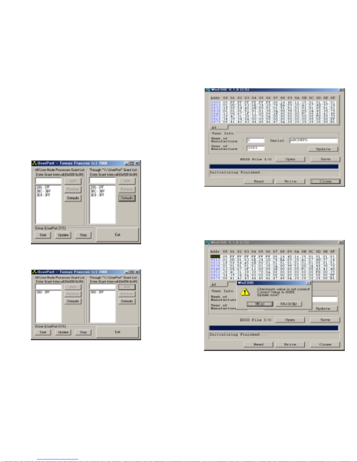
Windows EDID V1.0 User Manual
Operating System: MS Windows 98, 2000, XP
Port Setup: Windows 98 => Don’t need setup
Windows 2000, XP => Need to Port Setup.
This program is available to LCD Monitor only.
1. Port Setup
a) Copy “UserPort.sys” file to
“c:\WINNT\system32\drivers” folder
b) Run Userport.exe
c) Remove all default number
d) Add 300-3FF
e) Click Start button.
f) Click Exit button.
2. EDID Read & Write
1) Run WinEDID.exe
2) Edit Week of Manufacture, Year of Manufacture,
Serial Number
a) Input User Info Data
b) Click “Update” button
c) Click “ Write” button
Altri manuali per Flatron L1720B
2
Indice
Altri manuali LG Monitor

LG
LG 42PM11 - MU - 42" Plasma Panel Manuale utente

LG
LG Flatron L1750E Manuale utente

LG
LG 22MK600M Manuale utente

LG
LG L1942TE Manuale utente

LG
LG UltraGear 24GL600F-B.BFB Manuale utente

LG
LG Flatron W2242T Manuale utente

LG
LG UltraGear 24GL600F Manuale utente

LG
LG N1941ML Manuale utente

LG
LG UltraGear 38GN950P-B Manuale utente

LG
LG L206WTG Manuale utente


