
LG V-C7050HT Manuale utente

VACUUM CLEANER
SERVICE MANUAL
MODEL: V-C7050NT, V-C7050HT
V-C7070CT, V-C7070CP
CAUTION
BEFORE SERVICING THE UNIT, READ THE “SAFETY PRECAUTIONS”
IN THIS MANUAL.

2
CONTENTS
SAFETY PRECAUTIONS ......................................................................................................................... 3
CAUTIONS................................................................................................................................................ 3
DESCRIPTION.......................................................................................................................................... 4
SPECIFICATIONS..................................................................................................................................... 4
DISASSEMBLY ......................................................................................................................................... 5
TROUBLE SHOOTING ..............................................................................................................................6
BLOCK DIAGRAM.....................................................................................................................................9
SCHEMATIC DIAGRAM ............................................................................................................................9
CIRCUIT DIAGRAM.................................................................................................................................. 9
EXPLODED VIEW ...................................................................................................................................13
REPLACEMENT PARTS LIST.................................................................................................................17
APPENDIX .............................................................................................................................................. 19
1. THE TYPE OF POWER CORD & PARTS NUMBER .................................................................................19
2. COLOR & PARTS NUMBER..................................................................................................................20
3. MOTOR & PWB ASSY PARTS NUMBER ................................................................................................20

3
BEFORE OPERATING THIS VACUUM CLEANER, READ THIS SERVICE MANUAL THOROUGHLY,
AND OBSERVE EACH POINT CAREFULLY.
BEFORE ATTEMPTING TO SERVICE OR ADJUST ANY PART OF THE VACUUM CLEANER, DISCONNECT
THE ELECTRICAL POWER SUPPLY CORD FROM THE WALL OUTLET.
1. Motor filter(Air Cleaner)
1) This filter is reusable.
2) Never use the vacuum cleaner without filter.
It may damage the motor.
3) When the light of body is on, wash the motor filter
with water and brush.
4) Even if the light is not on, wash the motor filter at
least once 6 months.
NOTE : Reusing of the motor filter.
Never wash the filter in a washing machine or in a
dishwasher.
Never use hot water for washing the filter.
Reuse the filter after drying it completely in the
shade for a day.
Do not dry near fire or direct sunray.
2. Exhaust filter(Washable HEPA filter)
1) This filter is reusable HEPA filter.
2) For clean air, theis filter must be assembled.
3) Wash the exhaust filter with water once a year.
NOTE : Reusing of the exhaust filter.
Never wash the filter in a washing machine or in a
dishwasher.
Never use hot water for washing the filter.
Reuse the filter after drying it completely in the
shade for a half day.
Do not dry near fire or direct sunray.
Do not brush the filter. This will cause permanently
damage allowing dust to by-pass the filter.
3. Avoid suction such materials as :
1) Liquid or wet dust :
Clogs the ventilation holes, reduces the suction
power significantly and harms the motor.
2) Inflammable liquids such as benzene, alcohol or
solvents.
3) Burning objects such as cigarette butts.
4) Bulky objects such as vinyl, paper etc.
5) Sharp objects such as needles, pins, metal, glass
particles etc.
4. Attachments
• Nozzle : For cleaning wooden floor, the room floor
and carpet.
• Dusting Brush and Crevice Tool:
For cleaning any crevice, inside corners of window
frames.
For delicate vacuuming of fabrics on the furniture,
curtains, etc.
• Upholstery Nozzle : For vacuuming the dust on the
upholstery.
However, do not use the crevice tool more than 20
minutes because it may cause harm to the motor.
5. Close supervision is necessary when this
vacuum cleaner is used by or near children.
Children’s carelessness may cause damage to
the cleaner or injure persons.
6. Air exhausted from the vacuum cleaner is
normally warm. But if extraordinarily hot air is
exhausted, check if the telescopic tube, hose or
clean filter is clogged or not.
7. Electric shock could occur if used outdoors or
on wet surfaces.
1. Motor exchange
1) Separate the Body Cover and Body Base by
unfastening the screws.
2) After disconnecting the lead wires, replace the old
motor with a new one.
2. In case of exchanging other parts. refer to the
exploded view.
SAFETY PRECAUTIONS
CAUTIONS
4
DESCRIPTION
SPECIFICATIONS
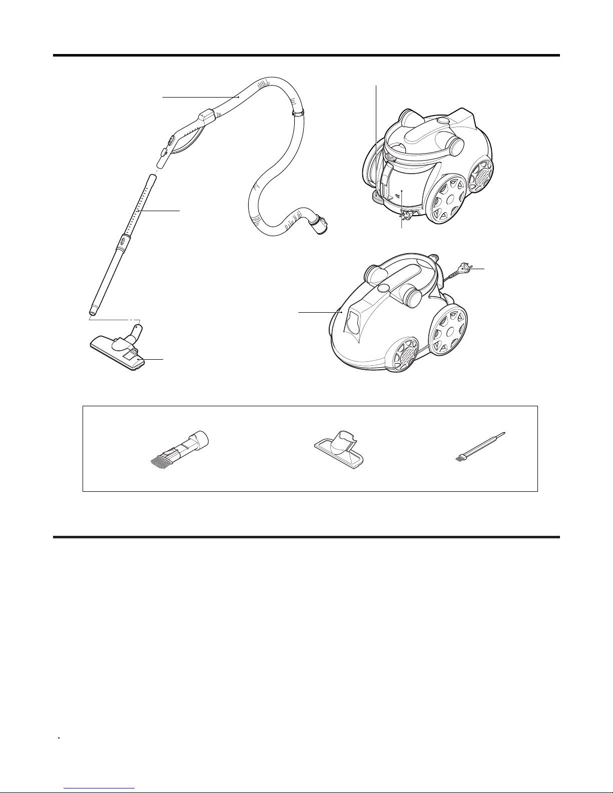
Telesscopic
Pipe ASS'Y
Flexible Hose ASS'Y
ATTACHMENTS
Power Cord
Filter Cover
Nozzle ASS'Y
Cord Reel Button
Dust Tank
UPHOLSTERY NOZZLEDUSTING BRUSH & CREVICE TOOL BRUSH ASS'Y
This specifications are subject to change according to the buyer’s request.
•MODEL : REFER TO THE COVER PAGE
•POWER SOURCE : ON RATING PLATE
•POWER CONSUMPTION : ON RATING PLATE
•POWER CONTROL :
- MAIN : SLIDE CONTROL (F/HOSE)
(V-C7050HT)
MICOM CONTROL (F/HOSE)
(V-C7070CT)
PUSH ON/OFF(BODY)
(V-C7050NT)
- SUB : VACUUM POWER ADJUSTMENT BY
SLIDE KNOB (V-C7050NT)
•CORD LENGTH : 7m
•HOSE LENGTH : 1.8m
•NET WEIGHT : 5.3Kg
•PACKING WEIGHT : 8.4Kg
•NET DIMENSION : 290 ×443 ×311(W ×D ×H)mm
•
PACKING DIMENSION : 330 ×567 ×385(W × D × H)mm
•ATTACHMENTS
HOSE ................................................................ 1EA
TELESCOPIC PIPE ASSY ................................ 1EA
NOZZLE ASSY.................................................. 1EA
DUSTING BRUSH & CREVICE TOOL.............. 1EA
UPHOLSTERY NOZZLE ................................... 1EA
BRUSH ASS'Y................................................... 1EA
CANISTER

5
•
Almost all the parts of this vacuum cleaner can be
disassembled with a screw driver and each connecting
component easily fits each other.
Disassemble one by one referring to the exploded view.
•If possible, don’t disassemble except for the
necessary parts. It is not necessary to disassemble
the parts that are not detailed in the exploded view.
DISASSEMBLY
NOTE: Before attempting to service or adjust any part of the vacuum cleaner, disconnect the electrical
power supply cord from the wall outlet.
Motor Ass'y
Cord Reel Ass'y
1. Body Cover Assembly Replacement
1) Remove the dust tank from the set.
2) Remove the four screws fastening the body base.
2) Bring out the motor and disconnect the lead wires
from it.
3. Cord Reel Assembly Replacement
1) Remove the cord reel cover by unfastening the
screw.
2) Lift the cord reel assembly from the body base.
3) Disassemble the filter cover, widening the both of
filter cover, and then pull out the lead wires from
the push switch.
2. Motor Assembly Replacement
1) Unhook the motor housing cover in the direction
of the arrow.

6
TROUBLE SHOOTING
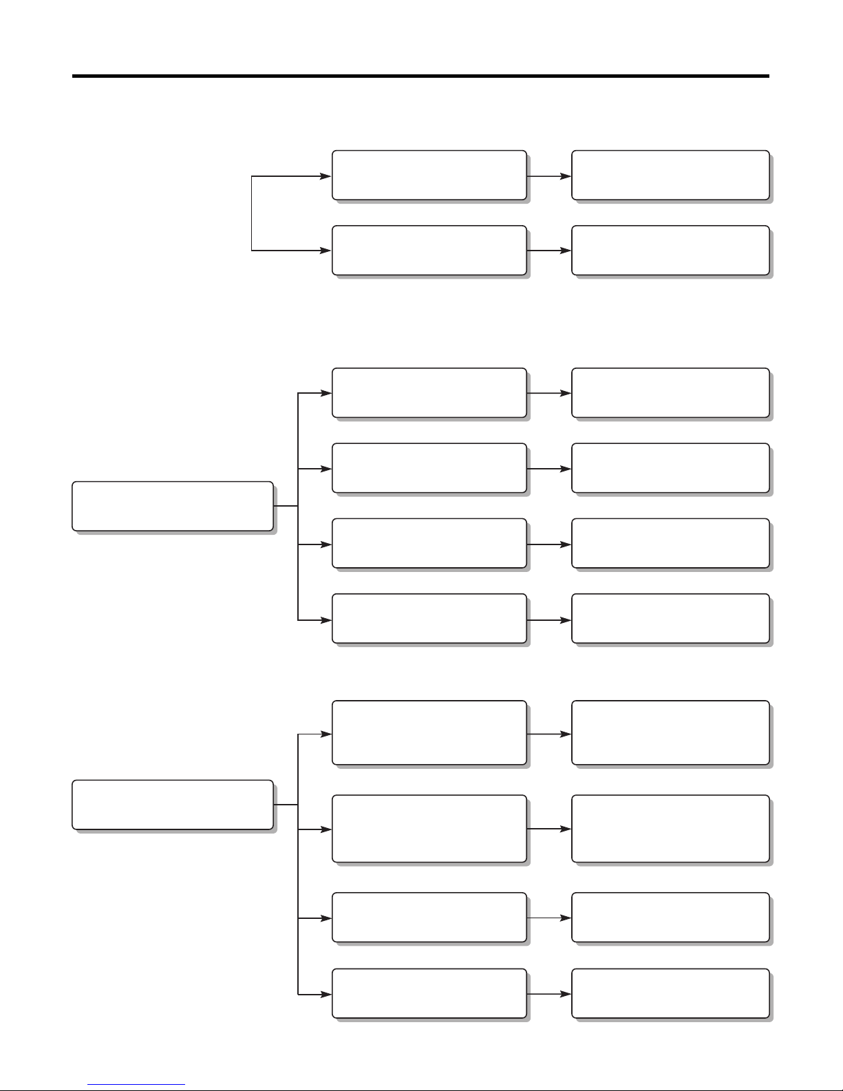
1. SWITCH ON BUT MOTOR DOES NOT TURN
2. SWITCH ON, MOTOR DOES NOT TURN BUT BUZZES
CHECKING
CHECK THE POWER
SOURCE
The fuse is melt down in the
coverknife switch.
Exchange the fuse.
Poor plug insertion Insert again.
Power cord cut Repair or exchange.
Interior lead wire cut Exchange the lead wire.
Motor(stator, armature) coil
cut or damaged. Exchange the motor.
Poor contact carbon brush
defaced. Exchange or repair the motor.
Poor switch contact point Exchange the switch.
Motor armature cut. Exchange the motor.
Ball bearing defacement Exchange the motor.
Impeller hindrance
(Caused by foreign matters) Remove the foreign matters.
CAUSE SOLUTION
7
3. SWITCH OFF BUT MOTOR TURNS
4. WEAK SUCTION POWER
Carbon brush defaced Exchange the carbon brush
or the motor.
Motor armature cut Exchange the motor.
Foreign matters attached to
the impeller Remove the foreign matters.
Low voltage Inquire to the power utility
company.
Hose and extension wands
are clogged with foreign
matters.
Remove the foreign matters
in the hose or extension
wands.
The slide knob on the handle is
opened or the control knob is
located on weak position.
Close the slide knob by sliding it.
Regulate the knob.
The motor filter is clogged. Clean the motor filter.
The exhaust filter is clogged. Exchange the exhaust filter.
Poor connection Repair.
Poor switch
Low rotation speed
Motor turns normally,
but suction power is weak.
Exchange the switch.

8
5. VIBRATION NOISES
6. RADIO, TV RECEPTION DISTURBANCE
7. IMPROPER TUBE OR NOZZLE CONNECTION
Loose parts Secure firmly.
Unbalanced motor assembly Exchange or repair the motor.
Foreign matters are attached
to the impeller. Remove the foreign matters.
Poor carbon brush rectification Exchange the motor.
Poor cord, lead wire Exchange cord, lead wire.
Poor rectification of
carbon brush Exchange the motor.
Poor electric connector or
receiver
Repair the electric connector
or receiver.
Poor capacitor Exchange the capacitor.
Bent connection parts Exchange the parts.
Poor connection
(Caused by foreign matters)
Remove the foreign matters
and reconnect.
Armature is cut or foreign
matters attached.
Exchange the motor
Remove foreign matters.

9
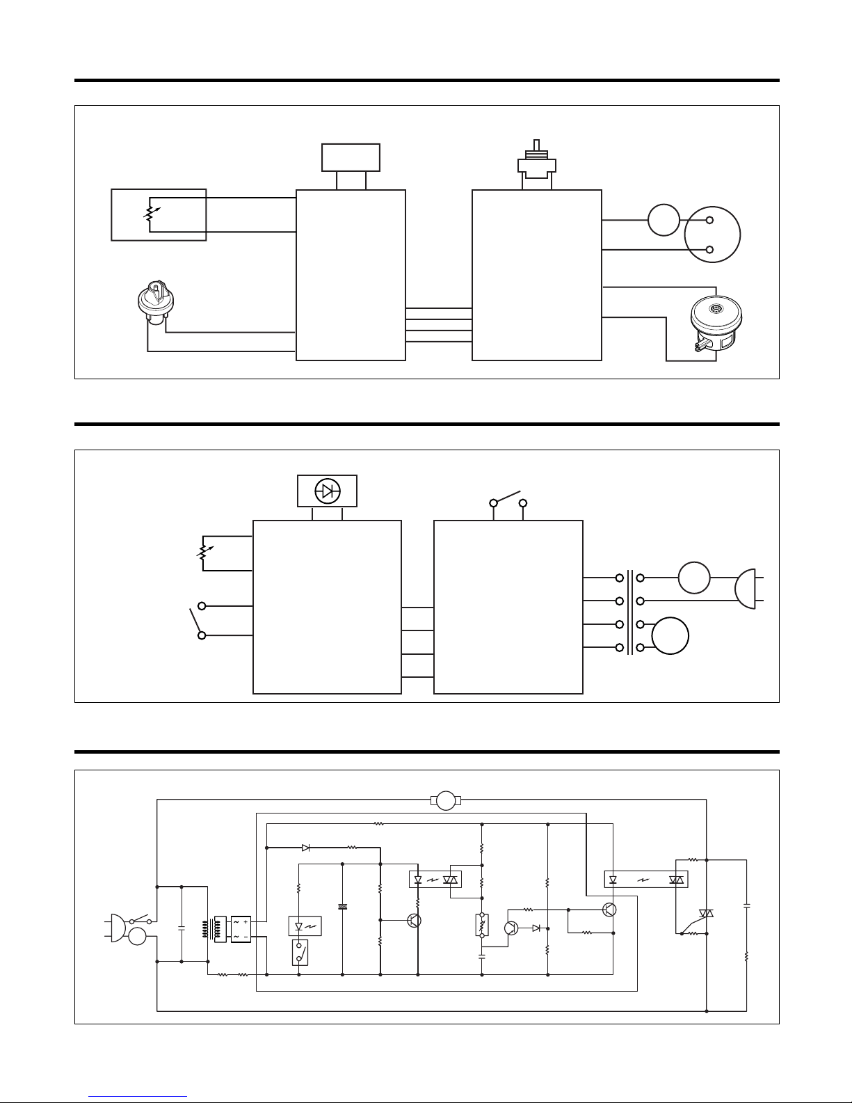
BLOCK DIAGRAM (V-C7050NT)
SCHEMATIC DIAGRAM (V-C7050NT)
PRESSURE S/W
POWER S/W CORD REEL ASS'Y
LED PWB ASM
MOTOR
PLUG
MAIN
PWB
ASM
GY
GY
BK GY
RD
BR BR
RD
BL
BL
T/P
M
C1
0.47µF
250V
C5
0.1µF
250V
C2
0.1µF
250V
R1
100
1/2W
C4
100GµF
16V
R6
10,1/2W D1
1N4007
Q1
C3198
FLICKER
C3
OPTO-TRIAC
16
24
PRESSURE
S/W
LED1
6871FX3078
POWER S/W
ZD1
5.6V
R11
470
R7
3K R9
470
R3
110K
R10
3.9K
1/2W
R2
33
1/2W R4
33
1/2W
DIAC
T1
G
TRIAC
T2
R8
1K
+
T/P
POWER S/W
PRESSURE S/W
BR
GY
GY
BR
BK GY
RD
RD
BL
BL
LED PWB ASM
M
MAIN
PWB
ASM
T/P
CIRCUIT DIAGRAM (V-C7050NT)
10
BLOCK DIAGRAM (V-C7050HT)
SCHEMATIC DIAGRAM (V-C7050HT)
PRESSURE S/W
SLIDE VOLUME
HOSE
POWER S/W
LED PWB ASM
SUB
PWB
ASM
MAIN
PWB
ASM
BR BR
RD
RD
BL
BL
BK
GY
GY
GY
T/P
POWER
S/W
MOTOR
BD1
C1
0.47uF
/AC250
R1
470K
1/2W
R10-1
470K
1/2W
R16
1.5K
R12
5.6K
R13
1K
C4
2200uF
16V Q3
C3198
C3
0.47uF
/100V
D6
1N4002 R11
390
IC2
R14
100
R9
100
R15
12K
S/VOL
R5
100
D5
1N4148
Q2
A1015
Q1
C3198
R7
13K
R6
18K
IC1
R4
11K
R3
470
1/2W
C2
0.1uF
630V
T2
T1
G
R1
100
1/2W
R2
330
1/2W
VR/
20K
R8
1K
LED1
M
+
TRANSTRANS
PRESSURE
S/W
PRESSURE
S/W
PHOTO-TRIACPHOTO-TRIAC PHOTO-TRIACPHOTO-TRIAC
T/P
LED PWB ASM
SLIDE VOLUME
PRESSURE S/W
POWER S/W
SUB
PWB
ASM
MAIN
PWB
ASM
GY
BR BR
GY M
T/P
CIRCUIT DIAGRAM (V-C7050HT)
Questo manuale è adatto per i seguenti modelli
3
Indice
Altri manuali LG Aspirapolvere

LG
LG VC4918URT Manuale utente

LG
LG A9T-ULTRA Manuale utente

LG
LG V-K80101HFR Manuale utente

LG
LG V-CR573S Manuale utente

LG
LG VR6270 Series Manuale utente

LG
LG V-C32**N series Manuale utente

LG
LG V-K81101HF Manuale utente

LG
LG V-KC801 Series Manuale utente

LG
LG VP07 WNV Series Manuale utente

LG
LG CordZero A9 Series Manuale utente

LG
LG VC31 N Series Manuale utente

LG
LG VK8820NHAQY Manuale utente

LG
LG VK882 series Manuale utente

LG
LG V-CR56 S Series Manuale utente

LG
LG VC3016GHTQY Manuale utente

LG
LG VK8920 Series Manuale utente

LG
LG V-CF751NTG Manuale utente

LG
LG VK7920UHT Manuale utente

LG
LG VC38 R Series Manuale utente

LG
LG VK89502HU Manuale utente


