Lightning Bicycle P-38 Istruzioni per l'installazione e il funzionamento

INTRODUCTION
This manual contains information on how to properly
adjust and operate your Lightning bicycle for maximum
comfort, safety, and performance.
The recumbent position and seat require alternate
adjustment methods. The unconventional design and
closeness of the front wheel to your feet require that new
riding skills must be acquired.
Carefully follow the instructions, and after a short period
of time, you will have the new habits needed to ride your
Lightning successfully.
CONTENTS
1.0 THE P-38 ASSEMBLY
2.0 ADJUSTMENTS BEFORE RIDING
3.0 RIDING
3.9 SAFE RIDING
4.0 ACCESSORIES
5.0 MAINTENANCE

1.0 THE P-38 ASSEMBLY
1.1 COMPLETE BIKE ASSEMBLY:
A) Remove all items from the box and unwrap. Be careful to
support the handle bars so that the cables are not kinked
B) Install the stem riser onto fork.
C) Install the rear derailleur. Install the wheels I the dropouts, and
check the tire pressure.
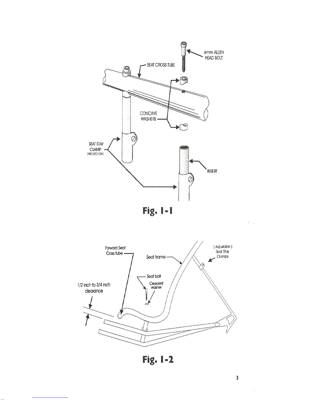
D) Loosely bolt the seat onto the frame using the included
hardware, coat the screws with grease to prevent corrosion (see
Fig. 1-1 and 1-2).
Adjust the seat stay inserts so that there is ½ to ¾ inch clearance
between the forward seat cross tube, and the top tubes.
Tighten all seat bolts tight.
E) Slide the cranks and bottom bracket assembly into the forward
frame tube, and install the pedals.
NOTE:
Do not apply any grease to the bottom bracket extension tube,
Otherwise it might rotate under pedaling pressure.
F) Adjust the crank length and tighten. Adjust the handlebar height
and tighten (See 2.0 ADJUSTMENTS BEFORE RIDING)
G) Front shifter connection/ adjustment:
Rotate lever until cable is fully released and thread cable to
Derailleur. Figure 1-3 shows the cable installation for the front
derailleur.
H) Rotate chain catcher to a vertical position (See Fig. 1-6).
Remove tape backing and gently tighten screw to secure in place.
I) Install the chain according to figure 1-4 (see 2.0 Adjustments
before riding for proper chain length).
J) Re-check the headset, breaks, and derailleurs for proper
adjustment and operation.


1.2 FRAME SET INFORMATION
A) Bend the brake levers down as shown. The best way is to hold
the upper part of the lever in the vise, heat the bent area with a
propane torch, and hit the end with a rubber mallet. Remember,
the right and left sides are opposite ( See Fig. 1-5).
B) Refer to Fig. 1-6 when routing the rear derailleur cable.
C) Fork:
1. O-Ring:
The included O-ring can be installed inside the head tube, and
presses against the fork steerer. This adds a small amount of
steering damping, thereby increasing the stability. See section 5-7
for installation info.
2. Suspended Fork:
When pressing the headset race onto the suspended fork, it is
important that the fit not be too tight. If the headset race is too
tight a fit, it can actually squeeze the steerer tube small enough to
that it locks up the sliding inner tube, thus preventing the fork from
reacting to bumps.
When installing a caliper brake on the suspended fork, it is
recommended locktite be used between the brake bolt and the hole
in the fork crown. This will provide for a stonger and longer
lasting assembly.
3. Caliper Brake:
Normally caliper brakes need to be mounted on the rear of the
fork to avoid chain interference. If you are installing a caliper
brake with recessed type mounting, the front mounting hole may
need to be drilled larger for the mounting nut. It will not void the
warranty nor make the fork too weak if this hole is made larger for
the mounting nut. Also you may need to remove the cable adjuster
for turning clearance, see Fig. 1-7
4. V-Brake:
See Fig. 1-8 for V-brake cable routing. Also the brake pads may
need to be turned around for safe operation, please check your
brakes closely.


Fig. 1-7
Fig. 1-8a

2.0 ADJUSTMENTS BEFORE RIDING
2.1 CRANK ADJUSTMENTS:
On Lightning Bicycles, The cranks are moved to accommodate
differences in leg length. Adjust the cranks as follows:
A) Loosen the two Allen head bolts under the crank tube with a
5mm Allen wrench.
B) Slide the cranks in or out until your legs are slightly bent at
their furthest extension (see Fig.2-1). It’s better to have the
cranks too close when making the initial adjustment that too
far away.
C) Verify the chainrings are vertical by sighting along them to
the handlebar stem, then tighten the two Allen head bolts.
2.2 HANDLEBAR ADJUSTMENT:
A) Slightly loosen the stem clam using a 6mm Allen
wrench.
B) Adjust the handlebars up or down so that there is
approximately ½ in of clearance between your knees and
the handlebars (Fig.2.1).
C) Verify the handlebars are at right angles to the front
wheel, then tighten the stem clamp.
CAUTION!
DO NOT TIGHTEN CLAMP ABOVE 50 IN-LBS
D) Slide the cable housing on the stem up or down to
prevent any tight cables during turning.

2.3 CHAIN ADJUSTMENT:
After adjusting the cranks, check and adjust the chain length.
The chain length should be long enough to permit shifting onto the
large front chain-wheel large rear sprocket combination, and at the
same time, not so long it goes slack when shifted onto small chain-
wheel combinations.
This can be accomplished by adjusting the chain length so that
the rear derailleur is in the position shown in fig. 2-2 with the chain
on the large chainring- large rear sprocket combinations.
CAUTION!
If the chain is not long enough to shift onto the large
Front chainwheel-large rear sprocket combination;
The rear derailleur and chain will break
NOTE:
The derailleur does not normally have sufficient take-up
Capacity to allow use of the small chainring- small rear sprockets.
Indice


