LightwaveRF LW452 Manuale utente

Connect Series
www.lightwaverf.house
2-Way Dimmer (2 Gang)
Model No. LW452
Instruction Manual
Version 2.1

EC DECLARATION OF CONFORMITY
Responsible Authority:
LightwaveRF PLC,
Innovation Campus Birmingham
Faraday Wharf
Holt Street
Birmingham
B7 4BB
Tel: +44 (0)121 250 3625
Model Number(s): JSJSLW452
Description: 2-Way Dimmer (2 Gang)
Directives this equipment
Complies with: 2006/95/EC The Low Voltage Directive N/A
2004/108/EEC The Electromagnetic Compatibility Directive
1999/5/EC R&TTE Directive
93/68/EEC CE Marking Directive
Standards Applied in order to verify compliance
Safety: BS EN 60730-1: 2011
Health:
R&TTE: EN 301 489-1 V1.9.2: (2011-09), EN 301 489-3 V1.4.1: (2002-08)
EN 300 220-1 V2.1.1: 2006, EN 300 220-2 V2.1.2: 2007
EMC: EN 301 489-1 V1.9.2: (2011-09), EN 301 489-3 V1.4.1: (2002-08),
EN 55022: 2010, EN 61000-3-2: 2006 +A1: 2009 +A2: 2009 Class A,
EN 61000-3-3: 2008, EN61000-4-2: 2009,
EN 61000-4-3: 2006 +A1: 2008 +A2: 2010, EN 61000-4-4: 2012,
EN 61000-4-5: 2006, EN 61000-4-6: 2009, EN 61000-4-11: 2004
For and on behalf of LightwaveRF PLC
----------------------------------------
Name J Shermer
Position Managing Director
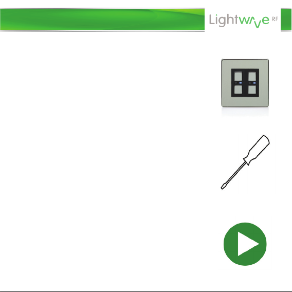
What do I need?
How do I get started?
To install the dimmer, you will need to remove
and replace the existing lightswitch. This is
usually straightforward, but you must ensure that
there is a suitably deep housing (backbox) and
understand how to safely turn o the electricity
supply. You will also need suitable electrical
screwdrivers.
Please refer to the following installation and
setup instructions. This will guide you, step by
step, through the installation and setup process.
Help video & further guidance
For additional guidance, and to watch a video
that will help guide you through the installation
process, please visit the support section on
www.lightwaverf.com
Get Started

Amber LED.
When illuminated,
the dimmer is o.
‘On’ button.
Hold to raise light
level.
‘O’ button.
Hold to decrease
light level.
Blue LED. When
illuminated, the
dimmer is on.
Overview
IMPORTANT: All LightwaveRF products can be legally DIY installed in your
own home; however, if in doubt, always consult a qualified electrician or
heating engineer. It is important to install this product in accordance with
the following instructions. Failure to do so may void your warranty.
Installation

Switched live
(live out)
Screw
mounting hole
Live in
2-Way
switching
connection
IMPORTANT: If conducting an insulation resistance test, all LightwaveRF
products must be disconnected from the mains, or damage will occur.
Installation

• The 2-Way Dimmers use standard 3 core connecting cables (or 3 core and
earth); however, because they are electronic dimmers, they utilise one of
the cores as a signal cable (‘S’) running between the Dimmers (as shown on
the diagram). This is low voltage only and should not be connected to
230V mains; serious damage will occur.
• Up to six 2-Way Dimmers (six gangs) can be connected to a standard
LightwaveRF Dimmer Switch. Each 2-Way can be connected directly to the
standard Dimmer, or connected to each other in a ‘daisy-chain’. This
provides an alternative to using intermediate switches (maximum cable
length of 100m).
VERY IMPORTANT
• A LightwaveRF 2-Way Dimmer needs to be used in conjunction with a
standard LightwaveRF Dimmer to perform 2-Way Switching. The
LightwaveRF 2-Way Dimmer cannot be used in conjunction with a
standard lightswitch. This will cause damage to the Dimmer.
• Never install and run power to a 2-Way Dimmer before first installing and
connecting the corresponding standard LightwaveRF Dimmer. Serious
damage could be caused to the unit.
Installation
1. IMPORTANT: Turn o the mains electrical supply.
2. Ensure that the wall (back) box has a minimum depth of 35mm.
3. Remove and disconnect the existing lightswitch (if applicable). It may be
useful at this point to mark out or take a photograph of the connections to
the existing switch so that the correct wires can easily be transferred to the
new dimmer. Some existing wiring configurations can be complex so take
care.
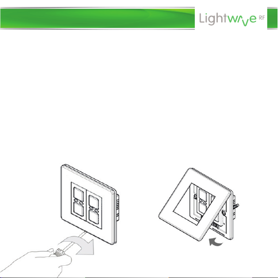
4. Gently remove the dimmer faceplate by inserting a screwdriver into one
of the bottom slots and lifting away from the unit as shown.
Installation

5. Connect the wiring as per the wiring diagram on the following page.
Ensure that the terminals are properly tightened and that no bare wire is
visible. Be aware that existing wiring circuits are not always correctly
coloured, and that there may be other wired connections present in the back
box; if in doubt, always seek the advice of a qualified electrician.
NOTE: LightwaveRF dimmers do NOT require a mains neutral wire to be
connected; they only require ‘live in’ and ‘switched live out’.
7. Screw the dimmer switch to the
mounting box and ensure that the
screws are suciently tight to support
the product, but do not over tighten as
this may cause the chassis to bend.
Ensure that the plastic spacer is
correctly aligned and that no wires are
trapped between the dimmer switch and
the back box.
6. Any earth wires present must be attached either to the earth terminal
located in the back box or capped with a strip connector. The dimmers are
double insulated so are not required to be earthed directly.
Installation

IMPORTANT: The signal cable input
marked ‘S’ must ONLY be connected
to the wire running to the other
dimmer NOT live mains; this will
cause irreparable damage.
3 or 4
core cable
From lighting circuit
Live
Live
Earth
Switched live
Signal cable
Switched live
Standard Dimmer 2-Way Dimmer
Installation
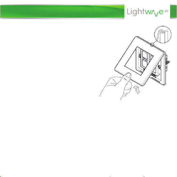
8. Replace the plate – a ‘click’ sound
should be heard to signify that the plate
has been correctly replaced.
Important things to consider
• Wattage ratings for the dimmers are
per gang. The maximum circuit
load for
each 2-Way Dimmer Gang is equal to
the maximum load on the standard
LightwaveRF Dimmer it is connected to
(i.e. 250W or 210W).
• ONLY dimmable lamps can be used even if the Dimmers are used solely to
switch between the on and o states without dimming. This is because the
technology used in an electronic dimmer is fundamentally dierent to that
of a simple on/o switch and requires compatible lamp technology.
NOTE: Compatibility between electronic dimmers and LEDs can be aected
if the total circuit loading is very small. Total LED load decreases (relatively)
as it is shared between a greater number of connected dimmers; therefore,
as more 2-Way Dimmers (up to 6) are added to a single circuit, it is possible
that LED performance may become less stable.
Installation
Indice
Altri manuali LightwaveRF Dimmer


