Linux MEGAsys Manuale utente

1
MEGAsys Linux DVR
Digital Video Recorder
User Manual

2

3
Table of Contents
CHAPTER 01 DIGITAL VIDEO RECORDER INTRODUCTION.................................. 1
CHAPTER 02
GETTING STARTED............................................................................. 8
CHAPTER 03
QUICK GUIDE TO ICONS ON THE MAIN SCREEN ......................... 13
CHAPTER 04
CONFIGURING THE CAMERAS........................................................ 16
CHAPTER 05
SCHEDULING RECORDING .............................................................. 19
CHAPTER 06
ACCOUNT SETTINGS........................................................................ 23
CHAPTER 0
SYSTEM SETTINGS ........................................................................... 25
CHAPTER 08
ALARM SETTINGS............................................................................. 34
CHAPTER 09
ALARM LOG ....................................................................................... 40
CHAPTER 10
USER LOG .......................................................................................... 43
CHAPTER 11
CONFIGURING GENERAL PURPOSE I/O ........................................ 45
CHAPTER 12
PAN TILT ZOOM................................................................................. 48
CHAPTER 13
PLAYBACK ......................................................................................... 52
CHAPTER 14
REMOTE SURVEILLANCE ................................................................ 63
Appendix - A
Backup to NAS (Network Attached Storage) .................................. 83
Appendix - B
NTP (Network Time Protocol) ........................................................... 85
Appendix - C
Audio................................................................................................... 8
Appendix - D
Multi-Playback.................................................................................... 90
Appendix - E
TROUBLESHOOTING ........................................................................ 92
Appendix - F
CONFIGURING ACTIVEX................................................................... 94
Appendix - G
Motion Detection................................................................................ 96
Appendix - H
Login Control ................................................................................... 100

4
Edition V.3.5.6
June 200 .

1
DIGITAL VIDEO RECORDER INTRODUCTION
Thank you for your purchasing the Digital Video Recorder (DVR) developed by our company!
This product has already obtained CE FCC BSMI Class A Certifications.
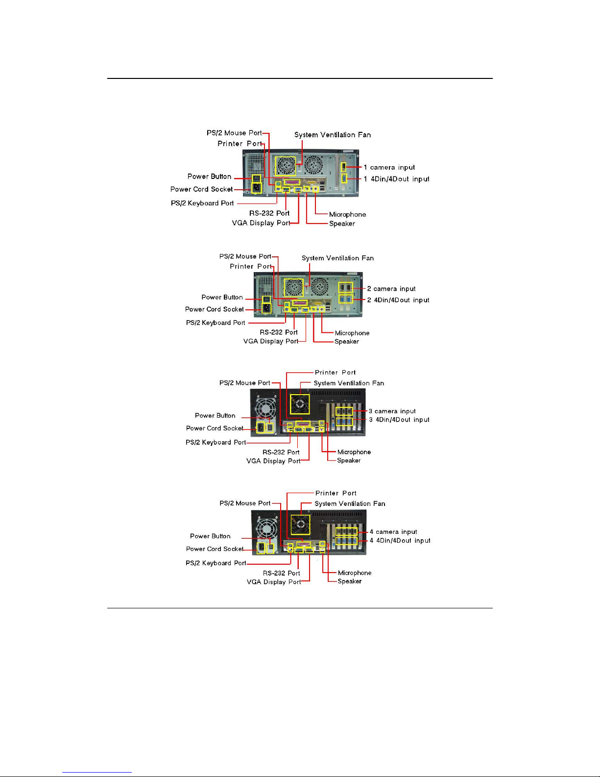
Our company has developed 4- 8- 12- 16-CH DVR system DVR central monitoring system
and various storage devices aimed at various security surveillance applications. The entire
series of products utilizes the most advanced digital technology and provides a broad range
of functions in order to completely satisfy your DVR application requirements.
Our DVR system has built-in digital compression technology for recording and streaming
video. Generally speaking a CCD camera can deliver clear crisp images at about 30 fps
(NTSC — National Television Standards Committee — US Television Standard) (25fps for
PAL—Phase Alternating Line — European Television Standard) — real continuous motion
requires 24 fps (frames per second standing for the number of the images delivered in one
second.) The high-performance processor and quick I/O connection not only provide you with
the capability to monitor the camera in real-time mode but also utilize the extra processing
power to allow for a high frame rate for recording and remote monitoring via I.E. browser so
that there will be a minimal loss of video frames. Users can determine the actual frame rate
required for recording and remote monitoring according to the amount of allocated disk space
and the bandwidth available.
For maximum expandability the system provides a Network Card allowing customers to
connect a computer system to monitor remotely through the network. A built-in 3½" floppy
disk drive (FDD) may be used for outputting video documents and other optional items
include memory storage/backup devices and alarm functions. Customers can choose to
purchase expandable modules according to actual needs.
This User’s Guide describes all features of the Digital Video Recorder in an easy-to-read yet
thorough manner. The primary goals of this chapter are to identify the main components of
the Digital Video Recorder and to provide a quick reference of the DVR functions for
experienced DVR users.
Chapter 1

2
Unpacking the DVR
The DVR comes securely packaged in a sturdy cardboard shipping carton. Upon receiving
your DVR open the carton and carefully remove the contents. If anything is missing or
damaged please contact your DVR dealer immediately and they will promptly handle the
situation. The shipping carton should contain the following items:
• The Digital Video Recorder
• A Power Cord
• The User’s Guide
• A Product Warra ty Card
• A Keyboard a d a Mouse
Do not throw the packaging materials away. You may need them
later to transport or ship the DVR for repairs.
Opening and Closing the DVR cover
If it is the 12-CH/16-CH model at the front of the Digital Video Recorder you will find a cover
protecting the hard disk drive cage and connectors. Make sure that the cover is in a closed
position when the DVR is not in use. The cover has a lock in the middle so please follow
these steps to open or to close the cover:
1. Tur the k ob of the lock a ti-clockwise, a d the cover ca be ope ed.
2. Whe the cover is i the closed positio , tur the k ob clock-wise to lock the cover.
The cover of the DVR is usually closed. Opening the front doors will reveal the slots for floppy
disk drive and hard disk.
Optional Devices
To further enhance the utility of your Digital Video Recorder there are several optional
products available:
• DDR RAM or SD RAM Modules
• Removable HDD Tray
• CD-Drive / CD-RW Drive / DVD-RW Drive / USB Devices
• 4 Di /Dout GPIO Cable
• Excha geable IDE Hard Disk/ IDE Expa sio Board/ Disk Array/ NAS Devices / DAT
Devices
• RS-232 I terface Modem
• IP shari g device
• UPS (U i terruptible Power Supply)

3
Overview o the Digital Video Recorder's Hardware Features
This section provides an overview of the Digital Video Recorder’s features as follows:
CPU
The central processing unit (CPU) is the DVR’s
key hardware feature; it acts as the brain of the
Digital Video Recorder performing all the
computing functions and orchestrating the
actions of the system.
Upgradeable
System Memory
Memory can be upgraded to 256MB
Power Management
The DVR features sophisticated power
management built into the complete BIOS Setup
program─Integrated Smart Charger Circuit
which is designed to restart the DVR
automatically as soon as the power is resumed
after a power cut.
FDD Module
The DVR comes with a built-
in FDD (Floppy Disk
Drive) module. The FDD can use 1.44MB high-
density 3.5" floppy diskettes.
Removable
HDD Tray
The DVR comes with a 3.5” hard disk. The hard
drive can easily be removed and replaced with
multiple hard drives for the purpose of data
backup or expansion.

4
Identi ying External Components
Please refer to the text and diagrams below to identify all external components and
accessories of the Digital Video Recorder.
Front View
4 or 8 Channel Type 12 or 16 Channel Type
Figure 1-1: Front View of the DVR
Front Inside View
Please refer to Figure 1-2 and the following descriptions to identify the components on the front side of
the Digital Video Recorder.
4 or 8 Channel Type
12 or 16 Channel Type
Figure 1-2: Front Inside View of the Digital Video Recorder

5
1. Removable HDD Tray
The metal HDD trays e able a secure fit for the HDD a d the air ve tilatio holes i fro t
e sure that air flows to the HDD thereby cooli g the system. (Optio )
2. HDD Lock
This lock uses a dedicated key to ope a d close the HDD tray. Use of a i correct key will
cause the HDD lock to malfu ctio .
3. HDD LED Indicators
The Red LED Light i dicates that the HDD is i use. The Gree LED i dicates the HDD is
powered o .
4. Floppy Disk Drive
The Digital Video Recorder comes with a built-i 3.5-i ch Floppy Disk Drive (FDD).
5. Floppy Disk Drive Eject Button
Press this butto to eject the floppy disk i the FDD.
6. Floppy Disk Drive LED
Whe the LED is gree , it i dicates that the power is o a d whe the LED is red, it i dicates
that the Floppy Disk Drive is i use.
7. Power Button
Press the power butto to tur the Digital Video Recorder o . Press the butto co ti uously for
10 seco ds to tur off the DVR.
8. Reset button
Restart the DVR system.
9. USB Port
This socket is used to co ect USB devices for data output purposes.
10. Speaker
This is used to make the alarm sou d.
11. Microphone
This is used for sou d i put.

6
Rear View
Please refer to Figure 1-3 and the following descriptions to identify the components on the rear side of
the Digital Video Recorder.
Figure 1-3: Rear View of Digital Video Recorder
1. Power Fan
This is used to cool the power supply.
2. System Ventilation Fan
This fa ve tilates the e tire system.
3. BNC Camera Input
Indice


