
Lumens VC-TA50 Manuale utente

To download the latest version of Quick Start
Guide, multilingual user manual, software, or
driver, etc., please visit Lumens
https://www.MyLumens.com/support
VC-TA50
Auto Tracking Camera
(PTZ Video Camera)
User Manual - English
[Important]

English -1
Table of Contents
Chapter 1 Package Contents.....................................................................................2
Chapter 2 Product Overview and Interface..............................................................3
2.1 I/O functions Introduction ..............................................................................3
2.2 Description of LED indicator..........................................................................4
Chapter 3 Instruction for installation........................................................................5
3.1 Scenario...........................................................................................................5
3.2 Camera Size.....................................................................................................5
3.3 Preparation before installation ......................................................................6
3.4 Instruction for installation..............................................................................6
Chapter 4 Introduction of Remote Control and Setting Menu..............................14
4.1 Remote Control.............................................................................................14
4.2 Setting Menu..................................................................................................15
Chapter 5 Network Function Settings Description................................................19
5.1 Connecting Camera to Network...................................................................19
5.2 Web Page Menu Function Description........................................................21
Chapter 6 DIP Switch Setting..................................................................................34
6.1 OUTPUT Switch.............................................................................................34
6.2 IR SELECT .....................................................................................................34
6.3 Camera Address Selector ............................................................................34
6.4 System Switch...............................................................................................34
Chapter 7 Troubleshooting .....................................................................................35
Chapter 8 Safety Instructions .................................................................................36
Supplier's Declaration of Conformity 47 CFR § 2.1077 Compliance Information.....37
Copyright Information ...................................................................................................38
English -2
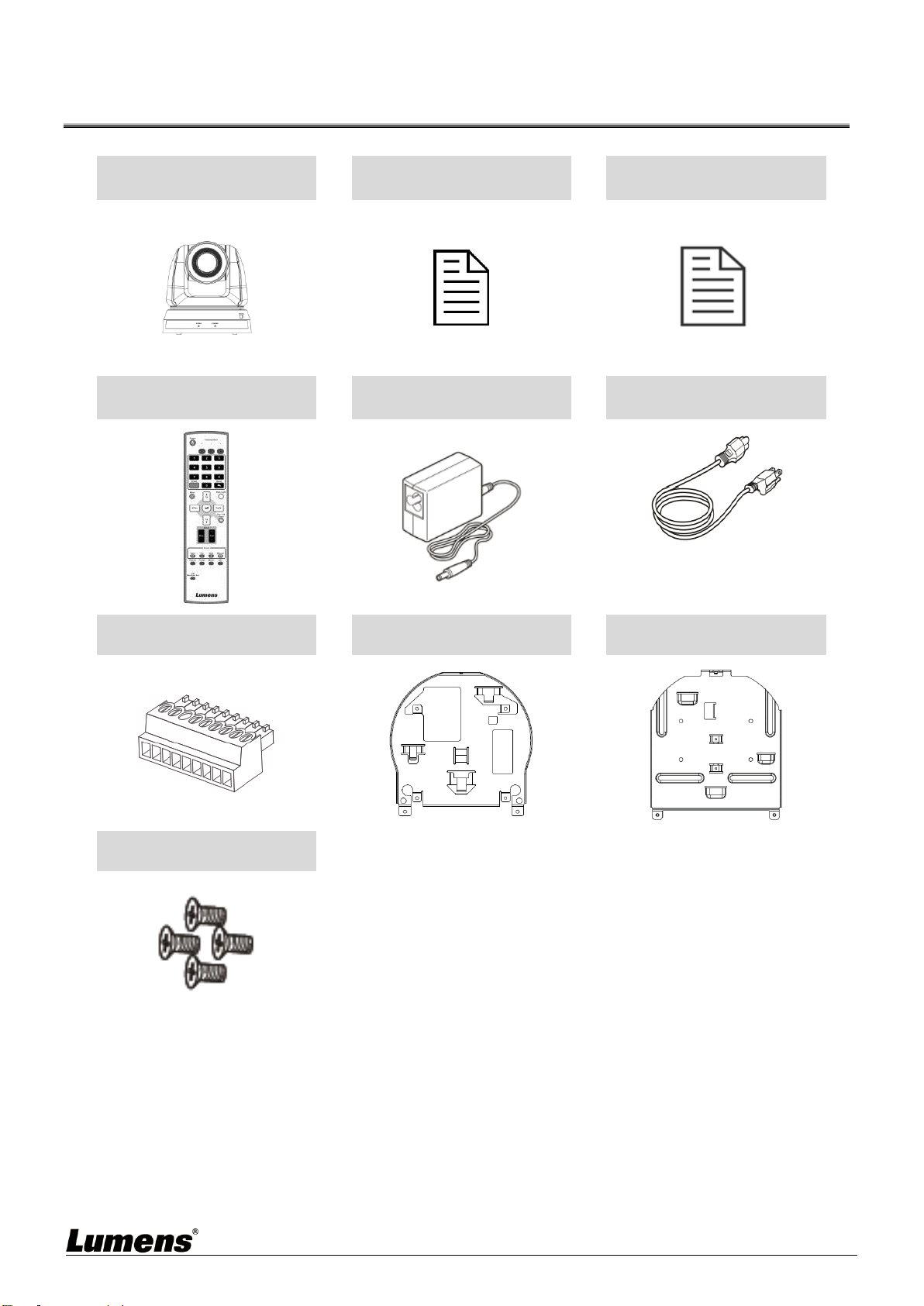
Chapter 1 Package Contents
Camera
Quick Installation Guide
RS232/RS422
Connection Instruction
Remote Control
Power Adapter
Power Cord
Appearance may vary
depending on
country/region
RS-422 Connector
Metal Plate A
Metal Plate B
M3 Screws
Silver x 8 / Black x 2

English -3
Chapter 2 Product Overview and Interface
2.1 I/O functions Introduction
Item
Function Descriptions
1. Camera lens
HD camera lens
2. Power LED
Display the status, please refer to 2.2 Description of
LED indicator
3. Standby LED
Display the status, please refer to 2.2 Description of
LED indicator
Item
Function Descriptions
4. Kensington lock
hole
Safety lock slot
5. Power input
AC power supply connecting port
6. Audio In
Support Line In/Mic In
7. RS-232 output
RS-232 output port, at most 7 cameras can be
connected in a serial connection
8. RS-232 input
RS-232 input port, at most 7 cameras can be
connected in a serial connection
9. RS-422 connecting
RS-422 connecting port, at most 7 cameras can be
connected in a serial connection
10.Network port
Support IEEE 802.3at PoE + power supply
11.HDMI output
HDMI output (support Audio output)
12.3G-SDI
3G-SDI output
13.OUTPUT Switch
Adjust the resolution setting. The default is 1920 x
1080/60p
14.IR SELECT
Remote control ID setting
It can be controlled only when it corresponds to the
Camera Select on the remote control
Item
Function Descriptions
15.Camera Address
Selectors
Camera ID Setting
16.SYSTEM Switch
System DIP Setting
17.Tripod lock hole
The camera is mounted on a (specification) 1/4” -
-20 UNC tripod
⑪
⑫
⑬
⑭

English -4
2.2 Description of LED indicator
Status
Standby
Power
Startup in progress
Green light
Orange light
In use
Green light
No indicator
In standby mode
No indicator
Orange light
Tally mode 1
Red light
Red light
Tally mode 2
Green light
Red light
Tracking Mode
Flickering green light
No indicator
<Remark> The Tally mode can be enabled via RS-232 command control. Please download the file for RS-232
Command Set from the Lumens website

English -5
Chapter 3 Instruction for installation
3.1 Scenario
3.1.1 Applicable distance range of VC-TA50: 4 - 15 m, best tracking target distance recommended:
8 m
3.1.2 Mounting height: 2 - 3 m, best height recommended: 2.4 m
<Note> For maintaining the best tracking results, avoid images of people on posters, screens, monitors, TVs in the
background
3.2 Camera Size
Length x Width x Height: 174 x 187 x 192 mm
Weight: 2.0 Kg

English -6
3.2.1 Dimensions of the bottom of the machine
The camera can be mounted on a 1/4”-20 UNC PTZ tripod deck by using the lock holes on the bottom for the tripod
3.3 Preparation before installation
Installation and connection of HD camera requires special skills. To install by yourself, please
follow necessary steps, ensure steady and tight installation of the device, and pay attention to your
safety to avoid any accident.
Ensure the safety of the installation environment. Please do not install the device on unstable
ceiling or in a place where the device is in danger of falling to avoid any accident.
Please check whether accessories in the box are complete or not. Please contact the supplier
for any shortage, and make sure to keep the accessories in the box intact.
Please choose a proper place for installation of camera in advance. Please determine an
installation place according to the following requirements
Confirm the position for the object to be captured.
Confirm whether the camera is set at a proper distance from other light sources.
3.4 Instruction for installation
3.4.1 I would like to install camera on the desk
3.4.1.1 Precautions for installation
Please install the machine on a flat desk
Do not grab the camera head by hand when handling the device
Do not rotate the camera head by hand. Improper rotation may result in breakdown of the camera

English -7
3.4.1.2 Installation steps
1. Please adjust DIP switch at first prior to installation
Please refer to Chapter 6 DIP Switch Setting for the relevant descriptions on DIP switch.
2. Place the camera on a flat desk directly to ensure the normal vertical and horizontal operation of the machine
3.4.2 I would like to install the camera on the ceiling
3.4.2.1 Prepare for the parts and equipment required during the installation
Accessories in the box (metal plates A, B, M3 screw silver x 8, black x 2)
Screw for locking on ceiling mounted hanger x 4
Drilling machine, screw driver, ladder

English -8
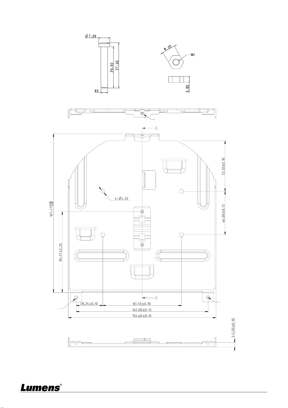
3.4.2.2 Metal Plate size diagram
Metal plate A - machine side
Metal plate A - machine side
Metal plate A locking screw
English -9
Metal plate B - ceiling side
Metal plate B - ceiling side
M3 threaded hole
M3 threaded hole
M3 threaded hole
Metal plate B locking screw
Metal plate B locking bolt
Altri manuali per VC-TA50
1
Indice
Altri manuali Lumens Macchina fotografica digitale

Lumens
Lumens VC-B30U Guida rapida

Lumens
Lumens VC-B11U Manuale utente

Lumens
Lumens DC-F20 Manuale utente

Lumens
Lumens VC-A50P Manuale utente

Lumens
Lumens VC-A61P Manuale utente

Lumens
Lumens VC-TR1 Manuale utente

Lumens
Lumens DC160 Manuale utente

Lumens
Lumens DC172 Guida rapida

Lumens
Lumens VC-A71SN Manuale utente

Lumens
Lumens VC-BR70H Guida rapida


