
MachPower AC-AFDSC-012 Manuale utente
User Manual
AUTOMATIC FLAP DOOR GATE
EN
Manuale d'uso
VARCO AUTOMATICO FLAP DOOR
ITA
Manual de usuario
PUERTA AUTOMÁTICA CON PUERTA ABATABLE
ES
AC-AFDSC-012 (Single Core) - AC-AFDDC-013 (Double Core)
AC-AFDSC-014 (Single Core) - AC-AFDDC-015 (Double Core)

2

ENG
3
Index
Product introduction
Installation instruction
Debug method instruction
Menu introduction
Main board Parameter
Turnstile wiring diagram
4
5
6
6
7
8

4
Product introduction
1. Equipment introduction
1.1 Category
Single core: used in single lane
Double cores: used in multi-lanes
2. Main function and characteristics
2.1 Function of standard product
1. With function of self-examine and alarm, it is convenient for maintenance and
use.
2. Being able to program running status by the small keyboard in the main board
3. Preventing pedestrians or bicycle from being nipped and from hurt
4. Sound or light alarm function
5. Poles are automatically locked until a opening signal is received.
6. Poles synchronization
7. Automatically reset function: It will automatically lock if the pedestrian hasn’t
pass through the channel in the pre-set time after the opening. The passing time
is adjustable.
8. Channels automatically open when power off, and automatically close when
power on.
9. Several card reading devices are attachable.
10. One direction or bi-direction control are optional.
11. It can be directly controlled and managed by remote control.
3. Standard technical parameters
Framework material 304/316 grade stainless steel
Framework size 1200(L) x 300(W) x 1000(H) mm
Length of the arms 260 mm
Working voltage AC220 ±10% V/50 ±10% Hz
Driving electromotor DC brush electromotor 24V
Input interface Dry contact signal or +12V level signal
driving current: > 10mA
Normal life-span 5 million times
5
ENG
Communication interface RS485 (standard)
Transit speed 30-40 persons/min
Card reader windows 4
Maintenance windows 4
Time for opening or closing 1 seconds
Starting time after power on 3 seconds
Working environment Indoor, outdoor( with a tent over)
Temperature -10°C ~ 50°C
Relative humidity ≤90% no condensation
Installation instruction
1. Installation on the ground
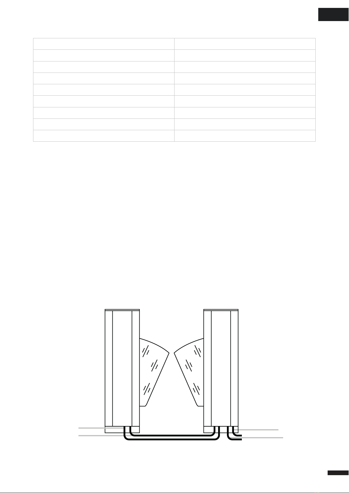
First of all, earthwork, a concrete base foot of 200mm height for anti-humidity
(hereinafter called Safe island) should be built. Then, power cable of
220V3 x 1.5mm and two 4 x 0.5mm (12 cores)control cables should be laid under
the middle of the casework.Fix the mechanism on the safe island.Connect it with
power of 220V and control cable should be linked to control room.
220V power cable 220V power cable
link cable link cable

6
2. Important notices
1. Without permission, please do not install any devices on the casework. Make
sure devices earthing is reliable and devices are in the condition of safety and
reliability.
2. When the devices are used in the open air, they should be install on cement
podium of 100mm---200mm height so as to avoid moisture; At the same time,
build a tent over the devices to keep from rain. Directly installation in the open air
is strictly prohibited.
Debug method instruction
1. Connect main board with power ,screen show “Flap barrier(swing barrier or
double swing barrier) ,In counter and out counter number
2. LCD screen have 5 button :Menu ,UP ,Down ,Enter and ESC
3. Main board have RS485 port ,can send turnstile gate command by RS485 port
4. Press menu button to input password ,password is press “UP” “UP” “DOWN””-
DOWN “UP” “DOWN
Menu introduction
1. Direction Config, Left in Right out,Left out Right in
2. Traffic control, L ban R enable, L enable R ban, All ban, All Enable
3. Working mode, L infrared R card, L card R infrared, All infrared, All card
4. Memory Func Config, L ban R enable, L enable R ban, All ban, All Enable
5. Open time, Number is optional
6. Counter reset
7. Machine NO
8. Machine Info
9. Machine type, Flap barrier, Swing barrier, Double swing barrier
10. System Ini, “will clear all info”
11. Left Audio
12. Right Audio
13. Motor Speed, Master motor, Client motor
14. Motor Max turn len
15. Allowed Infrared over

7
ENG
16. Delay Closing time
17. Swing barrier Dire, Open-left, Open-right
18. Break-in Operation, No close, Closed
19. Motor brake, Close, Open
20. Machine L-open set, UP+1 Down -1
21. Other option
22. Machine test
Main board Parameter
Brush motor flap barrier(swing barrier)main board parameter
Basic introduction
Input power Voltage DC24V Current4.5A
Working temperature -15°C ~ 60°C
Working humidity ≤80%
Main board consumption <2W
IP IP52
Input terminal
introduction
Switch power supply Voltage DC18V ~ 26V
Current 3A ~ 6.5A
IR sensor signal Voltage DC2.5V ~ 24V
Current 5mA ~ 20mA
Limit sensor Voltage DC2.5V ~ 24V
Current 5mA ~ 20mA
Open signal,
Fire signal
Dry contact signal or +12V le-
vel signal. driving curre 5mA ~
20mA
Battery 12V 1HA ~ 5HA
Serial port 485
Output terminal
introduction
Voice port 4Ω~8Ω 10W
Direction board port DC12 5mA~20mA
Motor port DC 24V <2A
Light port No
Clutch port No
Fire output port No
8
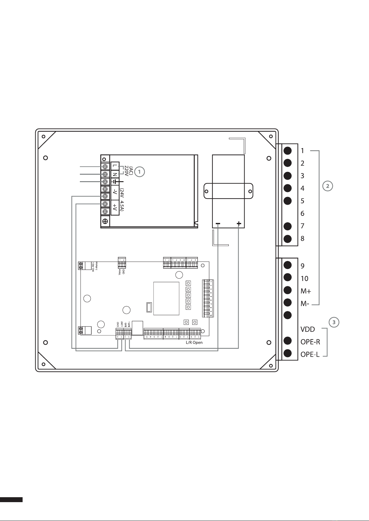
Turnstile wiring diagram
Flap barrier connection drawing
LCD
LINK CABLE L/R OPEN
MAIN PCB
POWER
SUPPLY
BATTERY
Remark: below 1, 2, 3 ned do cable connection


10
Questo manuale è adatto per i seguenti modelli
3
Indice
Lingue:


