Magnum MIG 160 Mini Manuale utente

1
MANUAL inverter
semi-automatic WELDING
Model:
MIG / MMA 160 Mini
Drawings devices in the manual may differ from the original colors.
Original instructions.
with
NOTE: Please use a welder after a very careful reading the manual.
1. In order to ensure safety should be determined by qualified personnel responsible for installation,
maintenance, periodic inspection and repair equipment.
2. In order to ensure safety before working with the machine carefully and with full understanding
refer to the following instructions.
3. After reading the following instructions and keep it in a place accessible to other users of the
device.

2
Table of Contents
1. INTENDED USE ............................................. 31. INTENDED USE ............................................. 31. INTENDED USE ............................................. 31. INTENDED USE ............................................. 3
2. TECHNICAL DATA .................................................. ........................ 32. TECHNICAL DATA .................................................. ........................ 32. TECHNICAL DATA .................................................. ........................ 32. TECHNICAL DATA .................................................. ........................ 3
3. PRECAUTIONS FOR USE ......................................... 4PRECAUTIONS FOR USE ......................................... 4PRECAUTIONS FOR USE ......................................... 4
4. SYMBOLS .................................................. .................. 74. SYMBOLS .................................................. .................. 74. SYMBOLS .................................................. .................. 74. SYMBOLS .................................................. .................. 7
5. CONSTRUCTION AND CONTROL PANEL .................................................. .... 85. CONSTRUCTION AND CONTROL PANEL .................................................. .... 85. CONSTRUCTION AND CONTROL PANEL .................................................. .... 85. CONSTRUCTION AND CONTROL PANEL .................................................. .... 8
6. KIT CONTENTS .................................................. ................. 9KIT CONTENTS .................................................. ................. 9KIT CONTENTS .................................................. ................. 9
7. USE .................................................. .............................. 97. USE .................................................. .............................. 97. USE .................................................. .............................. 97. USE .................................................. .............................. 9
7.1 Connecting to the network .................................................. ........................... 97.1 Connecting to the network .................................................. ........................... 97.1 Connecting to the network .................................................. ........................... 9
7.2 Inserting the conductors MIG-MAG welding. .................................. 107.2 Inserting the conductors MIG-MAG welding. .................................. 107.2 Inserting the conductors MIG-MAG welding. .................................. 10
7.3 Inserting the wire electrode. .................................................. ........ 107.3 Inserting the wire electrode. .................................................. ........ 107.3 Inserting the wire electrode. .................................................. ........ 10
7.4 Connection of protective gas. .................................................. .......... 117.4 Connection of protective gas. .................................................. .......... 117.4 Connection of protective gas. .................................................. .......... 11
7.5 MIG-MAG .................................................. ............. 117.5 MIG-MAG .................................................. ............. 117.5 MIG-MAG .................................................. ............. 11
7.6 Practical recommendations MIG-MAG welding. ......................... 117.6 Practical recommendations MIG-MAG welding. ......................... 117.6 Practical recommendations MIG-MAG welding. ......................... 11
7.7 Welding MMA .................................................. .................... 137.7 Welding MMA .................................................. .................... 137.7 Welding MMA .................................................. .................... 13
8. CLEANING AND MAINTENANCE .................................................. ... 148. CLEANING AND MAINTENANCE .................................................. ... 148. CLEANING AND MAINTENANCE .................................................. ... 148. CLEANING AND MAINTENANCE .................................................. ... 14
9. INTERFERENCE AT WORK WELDERS .............................................. ... 15INTERFERENCE AT WORK WELDERS .............................................. ... 15
10. STORAGE AND TRANSPORT ............................................. 15STORAGE AND TRANSPORT ............................................. 15STORAGE AND TRANSPORT ............................................. 15
11. UTILIZATION .................................................. ............................. 16UTILIZATION .................................................. ............................. 16UTILIZATION .................................................. ............................. 16
12. WARRANTY. .................................................. ........................... 16WARRANTY. .................................................. ........................... 16WARRANTY. .................................................. ........................... 16
13. STATEMENT OF COMPLIANCE .................................................. ............. 1713. STATEMENT OF COMPLIANCE .................................................. ............. 1713. STATEMENT OF COMPLIANCE .................................................. ............. 17

3
1. INTENDED USE 1. INTENDED USE
The device brand MAGNUM MIG / MMA_160_mini The device brand MAGNUM MIG / MMA_160_mini It is a semi-automatic welding
designed for manual electric welding of low carbon steel, low-alloy (MAG), alloy steel (MIG), and
aluminum and its alloys. The device can also be welded MMA using hot melt coated electrodes.
MIG / MMA_160_mini is designed for all kinds of welding work, locksmith workshop, repair shops, etc.
blacharniach car. Small dimensions, low weight and the ability to self-welding wire shielding, will
especially appreciate the professionals providing services in the field and builders.
The power source has been built on transistors IGBT of a minimum electromagnetic interference to improve The power source has been built on transistors IGBT of a minimum electromagnetic interference to improve The power source has been built on transistors IGBT of a minimum electromagnetic interference to improve
yield and reliability of the source current, less power consumption, and instant adjustment of the current to
changes in parameters during the welding process.
The manufacturer is not liable for damages resulting from misuse.
2. TECHNICAL DATA 2. TECHNICAL DATA
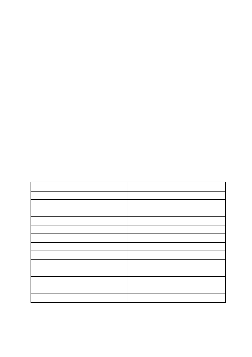
MODEL MIG / MMA 160 Mini
Power AC 230 [V], 50 [Hz]
Power consumption max. 3.8 [kW]
required safety 16 [A]
Current MIG / MAG 30 to 160 [A]
Power MIG / MAG 16.5 ÷ 22 [V]
Welding current MMA 30 to 130 [A]
Load voltage 58 [V]
The diameter of the wire spool / weight 100 [mm] / 1 [kg]
The diameter of the wire 0.6 / 0.8 / 0.9 [mm]
Welding "without gas" Yes
Efficiency 60 [%]
Enclosure IP21S
Net weight 6.5 [kg]

4
3. PRECAUTIONS FOR USE 3. PRECAUTIONS FOR USE
Please read all safety regulations and all instructions. Failure to comply with Please read all safety regulations and all instructions. Failure to comply with
safety regulations and instructions may result in electric shock, fire and / or serious
injury.
Keep all safety regulations and instructions for future use.
You can not allow children near the place of operation. People with pacemakers
take him to work with the device, should consult with your doctor. Service and
repair of equipment
They can be carried out by qualified personnel under the terms
safety applicable to electrical appliances.
Processing on their own may alter the functional characteristics of the device or deterioration of
welding parameters. Any modification of the equipment, on their own, cause not only void the
warranty, but may cause deterioration of the security conditions of use and exposure to the risk of
electric shock. Improper working conditions and improper handling can cause damage to the device
and void the warranty.
SAFETY INSTRUCTION
electric welding
3.1. General thoughts.
a) The work must begin rested, sober, dressed in clothing made of slow-burning fabric or leather, her
hair covered with a beret or cap, on the legs have shoes with trousers hardly inflammatory hands
welding gloves and personal protective equipment - apron leather, welding mask , goggles, personal
respiratory protective equipment.
b) Work related to installation, dismantling, repair and overhaul of electric welding equipment should
be performed by workers with the appropriate permissions.
c) the combination of several welding power sources should not cause exceedance, no-load condition, the
allowable voltage between the output circuits connected sources of energy.
d) circuit of the welding current should not be grounded, except for the cases when the objects welded are
connected to ground.
e) Welding the connecting wires welded to the subject power source to be connected directly to the e) Welding the connecting wires welded to the subject power source to be connected directly to the
subject or instrumentation, as close as possible to the welding point.
3.2. Basic steps before you begin work.
Welder should:
a) refer to the documentation of the executive and the scope of the welding work,
b) schedule the execution order of individual welds,
c) prepare a suitable adhesive,

5
d) prepare adequate protection face and eyes,
e) check the condition of the welding connections and the operating handle,
f) check whether the execution of the welding does not endanger the environment (radiation curve, the possibility of
ignition elements flammable)
g) check whether in the case of welding on the wall, the other side can not occur inflammation,
3.3. During welding operations.
a) Secure the workplace, as long as there is no fixed and mobile screens with anti
przeciwodpryskowymi.
b) Use for welding electric conductors and an operating handle only in good condition (intact
insulation).
c) Use only the correct thickness of the electrodes and wires for welding.
d) Attach and set reliably and solidly welded object and so has not been damaged.
e) Set the details to be welded in such a way as to prevent them from shifting or overturn.
When you flip slag needle use hammers and goggles.
f) When welding inside the boilers, tanks or in a confined space by whatever ventilation use f) When welding inside the boilers, tanks or in a confined space by whatever ventilation use
respiratory protection.
g) When operating inside the tanks, boilers and other metal rooms used electric lighting 24V.
h) Make sure that the welded part does not risk falling or moving away the dangerous to the welder.
and) When welding on scaffolding check the status of their efficiency.
j) Protect respiratory system, eyes, face and hands from burns and exposure through the use of appropriate
personal protection.
k) Switch individual air extraction, when this is established, the gaseous effluents are removed from the position.
l) Use only proper, undamaged and niezaoliwionych tools and support workshop.
3.4. Prohibited Actions.
Welder forbidden:
a) gripping the prepared hot metal welding or after welding.
b) Isolated repair damaged electrical cables (electrical system).
c) During work breaks stick under his arm electrode holder.
d) masks moving away too far from the welding face, her deposition before the arc goes out, as well as inflammation of the
arc without face protection.
e) Welding without proper grounding of the workpiece.
f) Use makeshift combination of welding equipment. f) Use makeshift combination of welding equipment.
g) Cause to the floor at the work station was wet, slippery, uneven, contaminated waste,
previously blocked.
3.5. Basic activities after work.
Welder should:
a) Switch off the welder energized.
b) Check whether the welding position or a position next to the fire was not dusty.
c) Organize your work station, remove the tip electrodes and welding slag.

6
d) Organize welding equipment.
3.6. Final remarks.
a) When performing welding work inside the tanks, boilers or other confined spaces (to 15m3), a
welder should be insured by another person, who will remain on the outside.
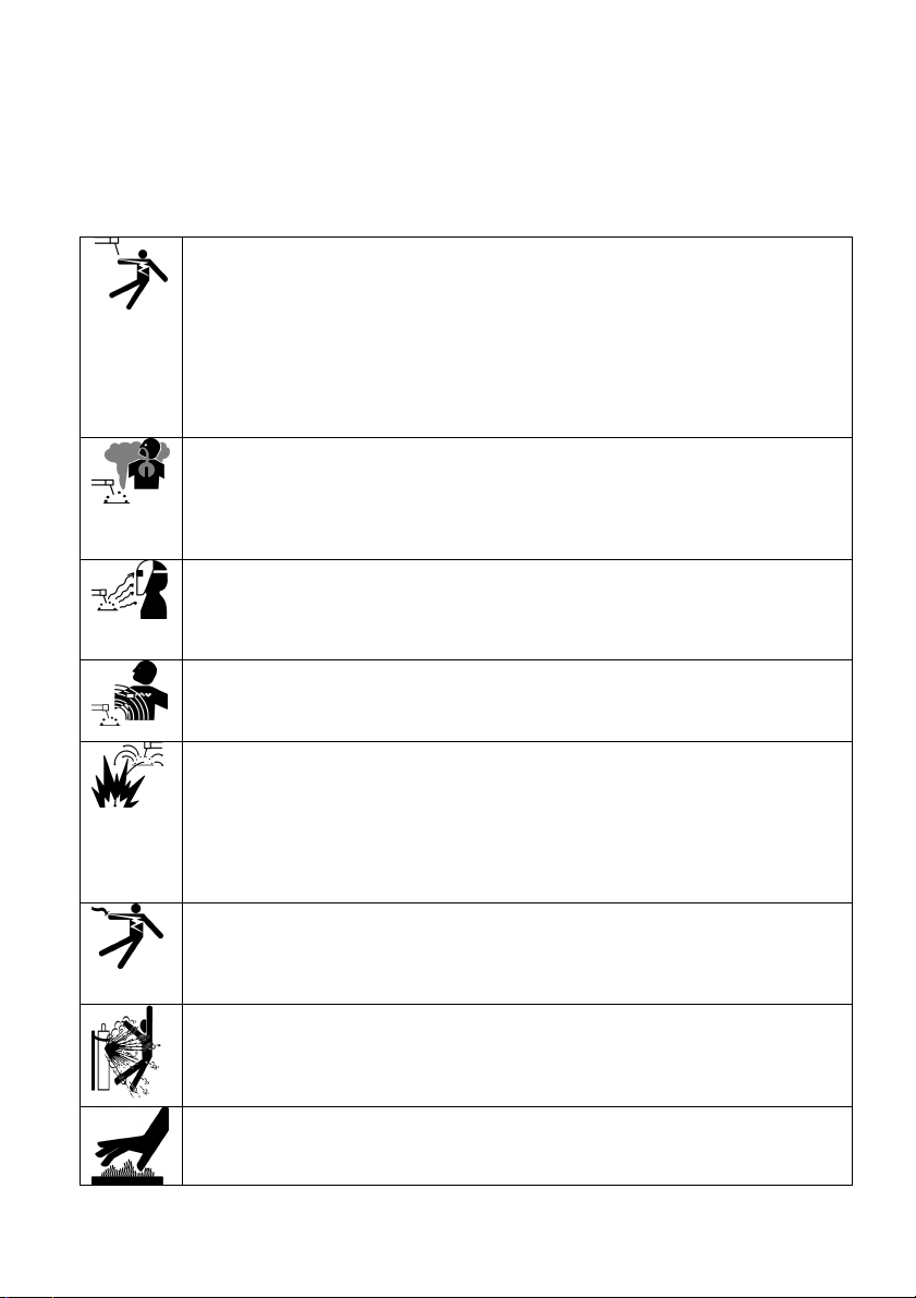
ELECTRIC SHOCK CAN KILL: Welding apparatus produce a high voltage. Do not touch the torch or welding material ELECTRIC SHOCK CAN KILL: Welding apparatus produce a high voltage. Do not touch the torch or welding material
connected when the device is turned on to the network. All the elements forming the welding current circuit can cause
electrical shock and should therefore be avoided touching them with bare hands or by wet or damaged protective
clothing. Never work on a wet surface, or use damaged welding cables.
NOTE: Removing the external time when the device is connected to the network, as well as the use of the device
with the covers removed is prohibited!
Welding cables, ground cable, earthing terminal and welding equipment should be kept in good condition, ensuring
safety.
FUMES AND GASES CAN BE DANGEROUS: In the welding process are produced noxious fumes and gases FUMES AND GASES CAN BE DANGEROUS: In the welding process are produced noxious fumes and gases
hazardous to health. Workplace should be adequately ventilated and equipped with exhaust ventilation. Do not weld in
confined spaces. Avoid inhalation of vapors and gases. The surfaces of the elements to be welded should be free from
chemical impurities such as degreasing agents (solvents) which decompose during welding to produce toxic gases.
ARC RAYS CAN BURN: It is not allowed to look directly at the eyes uncovered and exposed to the arc. Always wear a ARC RAYS CAN BURN: It is not allowed to look directly at the eyes uncovered and exposed to the arc. Always wear a
mask or helmets protected with a suitable filter. Bystanders, nearby, protected with non-combustible, absorbing radiation
screens. Protect the exposed parts of the body suitable protective clothing made of non-combustible material.
ELECTROMAGNETIC FIELDS MAY BE DANGEROUS: Electric current flowing through wires Welding produces ELECTROMAGNETIC FIELDS MAY BE DANGEROUS: Electric current flowing through wires Welding produces
electromagnetic field around it. Electromagnetic fields can interfere with pacemakers. Welding cables should be arranged
in parallel, as close as possible to each other.
SPARKS CAN CAUSE FIRE: Sparks generated during welding can cause fire, explosion and burns unprotected skin. SPARKS CAN CAUSE FIRE: Sparks generated during welding can cause fire, explosion and burns unprotected skin.
When welding should be wearing welding gloves and protective clothing. Remove or secure any flammable materials and
substances from the workplace. Do not weld closed containers or receptacles in which there were flammable liquids.
Such containers or tanks should be rinsed prior to welding in order to remove flammable liquid. Do not weld near
flammable gases, vapors or liquids. Fire extinguishing equipment (fire blankets and fire extinguishers powder or snow)
should be located close to the workstation in a conspicuous and easily accessible place.
POWER SUPPLY: Disconnect the power supply before carrying out any work, repairs on the device. Regularly check the POWER SUPPLY: Disconnect the power supply before carrying out any work, repairs on the device. Regularly check the
welding cables. If you note any damage to the wire or insulation they should be replaced immediately. Welding wires can
not be overwhelmed, touch sharp edges or hot objects.
CYLINDER could explode: Use only approved cylinders and a functioning regulator. The cylinder should be transported CYLINDER could explode: Use only approved cylinders and a functioning regulator. The cylinder should be transported
and stand upright. Protect against hot cylinders heat, and mechanical overturning. Keep in good condition all the
components of the gas system: tank, hose, fittings, reducer.
WELDED MATERIALS CAN BURN: Never touch the parts to be welded unprotected parts of the body. While touching WELDED MATERIALS CAN BURN: Never touch the parts to be welded unprotected parts of the body. While touching
and moving the welding material, always use gloves and welding pliers.

7
4. SYMBOLS 4. SYMBOLS
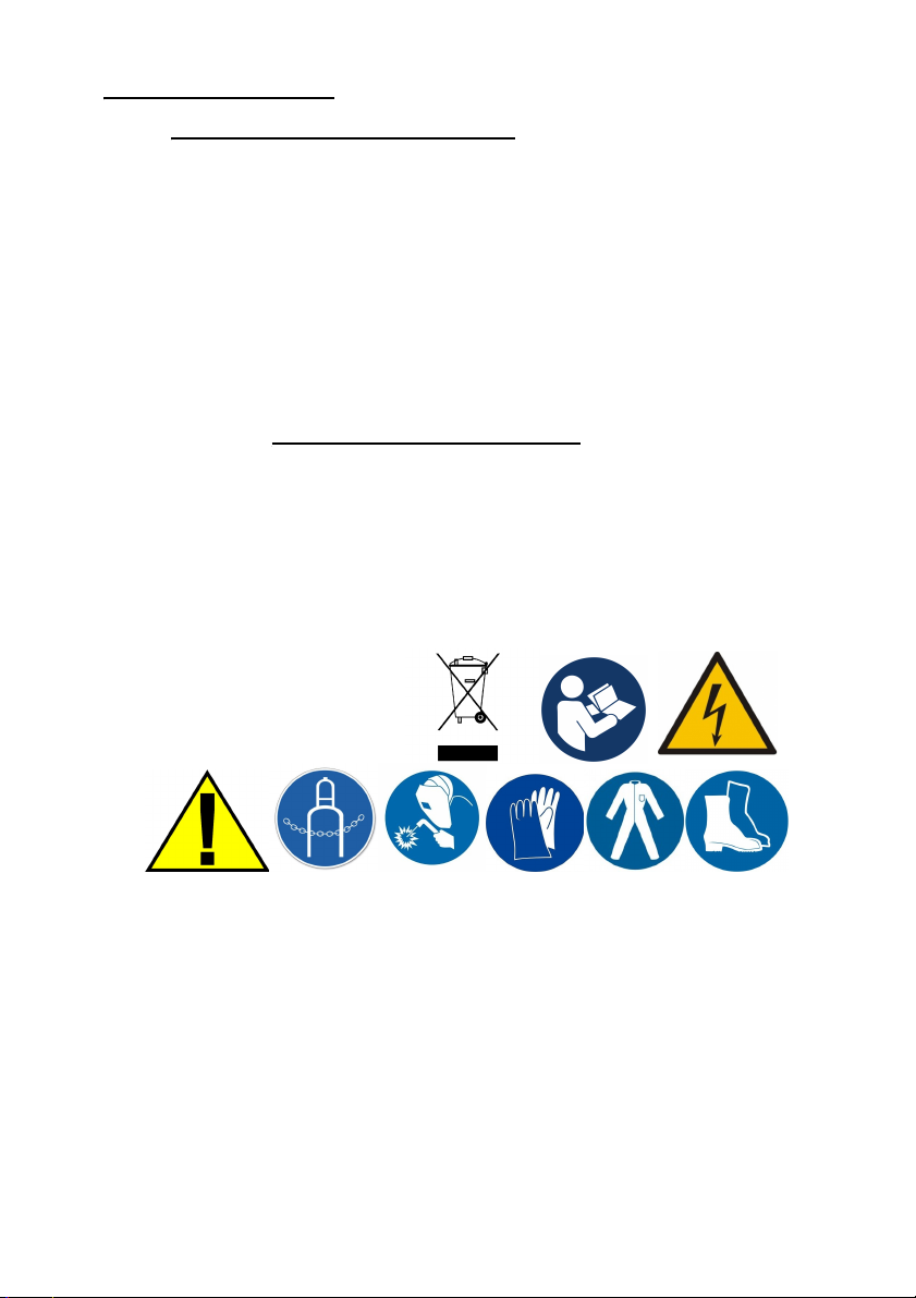
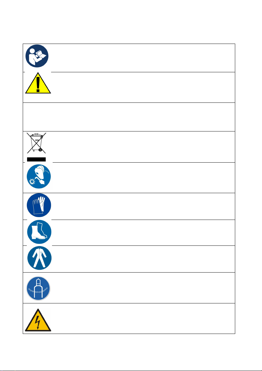
To reduce the possibility of injury, the user must first read all the instructions.
General warning sign notes for each user on the general danger. It is combined with
other instructions warning or other symbols that failure can lead to personal injury or
equipment damage.
The product complies with the requirements of European Union directives.
Disposal of electrical and electronic equipment - see DISPOSAL in this manual.
Use welding helmet or shield.
Use welding gloves.
Wear protective welding obligatory.
Wear protective welding kneading.
Secure the cylinder from falling over.
Risk of electric shock.
with

8
5. CONSTRUCTION AND CONTROL PANEL 5. CONSTRUCTION AND CONTROL PANEL
1
2
3
4
5
6
7
8
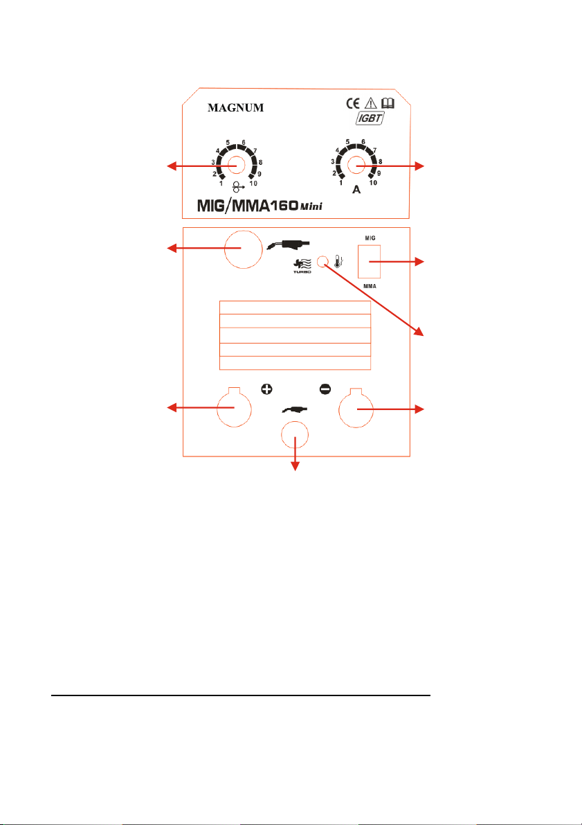
1. Welding current regulator. 1. Welding current regulator.
2. The switch methods MIG / MMA. 2. The switch methods MIG / MMA.
3. Signaling overheating. 3. Signaling overheating.
4. Current socket, output polarity "minus". 4. Current socket, output polarity "minus".
5. Adjusting dial wire feed speed. 5. Adjusting dial wire feed speed.
6. Ye operating handle. 6. Ye operating handle.
7. Current slot, the output polarity of the "plus". 7. Current slot, the output polarity of the "plus".
8. Cable to select the polarity for MIG-MAG 8. Cable to select the polarity for MIG-MAG
NOTE - WHEN MIG-MAG WELDING CABLE MUST BE CONNECTED TO THIS ONE OF SLOTS In: PLUS OR MINUS.
Main power switch and a connector for connecting the protective gas is at the back of the unit.

9
6. KIT CONTENTS 6. KIT CONTENTS
The following items should be included: The welding
device with a handle MIG-MAG x 1 pc.
Work cable MMA x 1 pc.
Cable to the common terminal x 1 pc.
Attention!
For the safety of children should not be left freely accessible parts of the packaging
(plastic bags, cardboard, polystyrene, etc.). Risk of suffocation!
7. USE 7. USE
7.1 Connecting to the network
Before switching the device to the mains, check the size of the voltage, phase and
frequency.
Parameters supply voltage are given in the technical specification section of this manual and on the
rating plate.
Check the grounding wire connection device to the mains. Make sure the power network can ensure
coverage of the power demand for the input of the device under its normal operation.
Fuse size and parameters of the power cord are given in the technical data of this manual.
The supply network should have a stable voltage. Cross-section of the supply lines should not be
less than 2.5 mm.
Devices which do not have power plugs connected by. tips listed below.
Connecting and sharing the power cord and the plug should be made by a qualified
electrician.

10
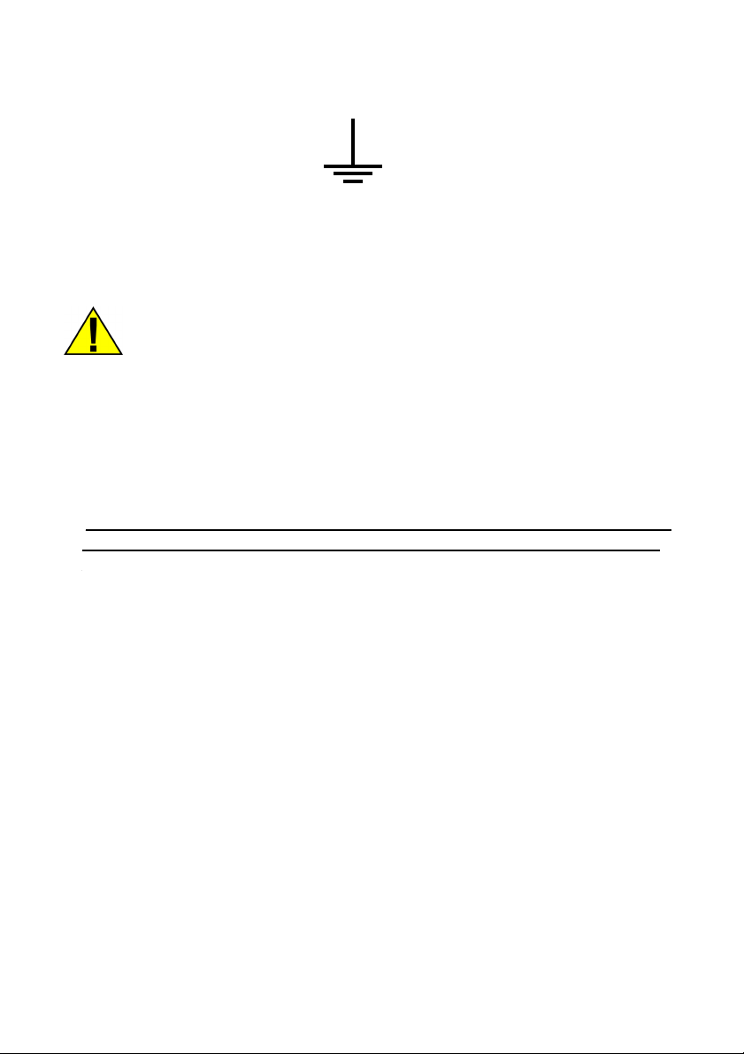
Insulated wire of yellow-green is grounded and should always be connected to the outlet marked
earth, regardless of whether there is power supply 230 [V] and 400 [V].
Symbol earth (PE).
7.2 Inserting the conductors MIG-MAG welding.
ATTENTION! Before all work carried out on the unit, unplug the power cord.
1. Make sure that the device is not connected to the mains. 1. Make sure that the device is not connected to the mains.
2. Check that the ground wire is terminated by a clamp or screw. 2. Check that the ground wire is terminated by a clamp or screw.
3. Plug the cable connected to the mass located on the front panel slot "4" or "7" push and twist. A 3. Plug the cable connected to the mass located on the front panel slot "4" or "7" push and twist. A
loose connection causes premature firing pin plug and socket current. The ground wire in the
MIG-MAG typically connect to the "- '', when using self shielding wire to the" + ".
In the second, empty nest insert connector connected to the built-in cable. It is necessary to
close the circuit. Without the plug plugged into one of the slots "4" or "7" unit will not weld!
4. Before putting the welding wire make sure the appropriate armor is established next to the 4. Before putting the welding wire make sure the appropriate armor is established next to the
appropriate diameter and type of electrode wire. To facilitate the manufacture of armor guiding them
label the appropriate colors. For a wire diameter
0.6 to 0.8 mm, a blue color, the wire having a diameter of 1.0 ÷ 1.2 mm, color red, and for a wire electrode
with a diameter of 1.6 mm color yellow. For welding stainless steel and aluminum, Teflon armor use. For the
welding of low carbon steel, low alloy steel, copper, bronze, etc., Are used with spiral metal armor. It should
be remembered accessories from the welding torch in the contact tip to the appropriate species and the filler
wire diameter.
7.3 Inserting the wire electrode.
1. Make sure that the roller mounted in the drive train correspond to the type and diameter 1. Make sure that the roller mounted in the drive train correspond to the type and diameter
the introduced wire. If the difference roll groove to the diameter of the wire electrode fit groove by
the reversal or replacement of the roll. For steel wire, use of rollers with V-shaped grooves, and
the aluminum wires of the U-shaped grooves may also be used knurled roll groove - are universal
rollers.
2. Place the spool of wire electrode on the spool mounting mechanism, paying attention to 2. Place the spool of wire electrode on the spool mounting mechanism, paying attention to
wire unwinding direction was consistent with the direction of the entrance to the wire drive unit.
3. Lock the spool before falling, by tightening the nut on the body of the reel. 3. Lock the spool before falling, by tightening the nut on the body of the reel.
Questo manuale è adatto per i seguenti modelli
1
Indice
Altri manuali Magnum Sistema di saldatura

Magnum
Magnum 100SG SPOOL GUN Manuale utente

Magnum
Magnum MIG200L PRO DUAL PULSE Manuale utente

Magnum
Magnum MIG 190 II DIGITAL Manuale utente

Magnum
Magnum WAVE 200KD Manuale utente

Magnum
Magnum MIG 208 Alu Synergy Manuale utente

Magnum
Magnum MIG 208 ALU SYNERGIC Manuale utente

Magnum
Magnum MIG 208 Alu Synergy Manuale utente

Magnum
Magnum CARIMIG 202LCD Manuale utente

Magnum
Magnum MIG 220 Alu synergy Manuale utente