Makita 1002BA Manuale utente

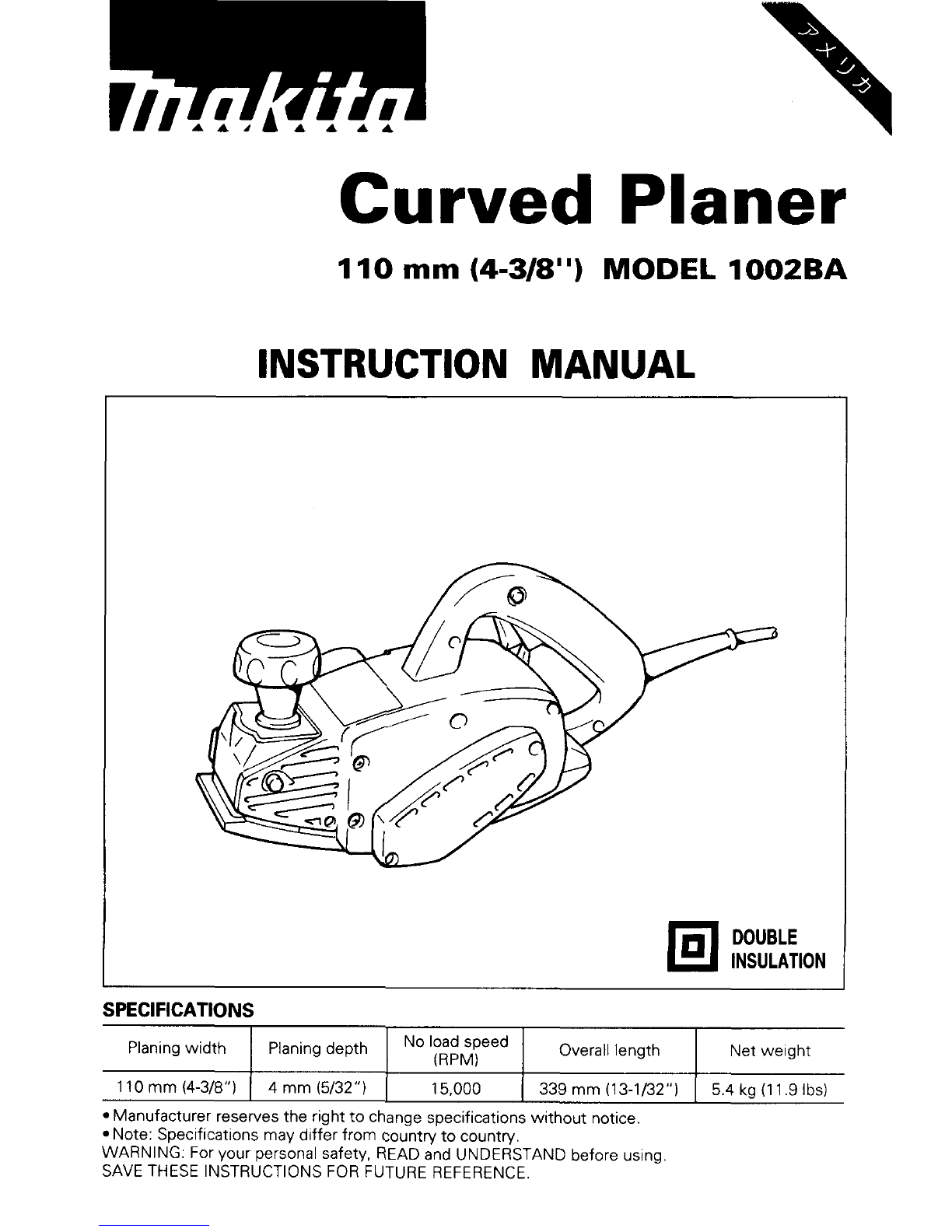
Curved
Planer
Planingwidth
110
mm
(4-3/8")
1
IO
mm
(4-3/8")
MODEL
1002BA
Planingdepth
No
loadspeed Overall length Net weight
4
mm
(5/32")
15,000
339
mm
(13-1/32")
5
4 kg (1
1
9
Ibs)
(RPM)
INSTRUCTION MANUAL

IMPORTANT
SAFETY INSTRUCTIONS
(For
All Tools)
WARNING:
WHEN USING ELECTRIC TOOLS, BASIC SAFETY
PRECAUTIONS SHOULD ALWAYS BE FOLLOWED TO REDUCE
THE RISK OF FIRE, ELECTRIC SHOCK, AND PERSONAL INJURY,
INCLUDINGTHE FOLLOWING:
1.
2.
3.
4.
5.
6.
7.
8.
9.
IO.
11.
12.
13.
-
READ ALL INSTRUCTIONS.
KEEPWORK AREA CLEAN. Cluttered areasandbenchesinviteinjuries.
CONSIDERWORK AREA ENVIRONMENT.Don't usepowertoolsindamp
or wet locations. Keep work area well
lit.
Don't expose power tools to
rain. Don't usetoolinpresenceof flammable liquidsor gases.
KEEPCHILDREN AWAY. Allvisitors shouldbekeptawayfromworkarea.
Don't letvisitors contacttoolor extension cord.
STORE IDLETOOLS. When notinuse, toolsshould bestored indry, and
highor locked-upplace
-
outof reachof children.
DON'T FORCE TOOL.
It
will
do the job better and safer
at
the rate for
which
it
wasintended.
USE RIGHTTOOL. Don't force smalltoolor attachment todothejob of a
heavy-duty tool. Don't use toolfor purpose not intended; for example,
don't usecircularsawfor cuttingtree limbsor logs.
DRESSPROPERLY. Don't wear
loose
clothingorjewelry.Theycanbecaught
in
moving parts. Rubber gloves and non-skidfootwear are recommended
whenworking outdoors.Wearprotectivehaircoveringtocontain longhair.
USESAFETY GLASSES. Also usefaceor dust mask ifcuttingoperation is
dusty.
DON'T ABUSE CORD. Never carry
tool
by cord or yank
it
todisconnect
from receptacle.Keepcordfrom heat, oil, andsharp edges.
SECURE WORK. Useclamps or
a
vise toholdwork. It's safer than using
your handand
it
frees bothhandstooperatetool.
DON'T OVERREACH. Keepproperfootingandbalanceat
all
times.
MAINTAINTOOLSWITHCARE. Keeptoolssharp andcleanfor better and
safer performance. Follow instructions for lubricating and changing
accessories.Inspecttoolcordsperiodically andifdamaged, haverepaired
by authorized service facility. Inspect extension cords periodically and
replaceifdamaged.Keephandlesdry, clean, andfreefromoilandgrease.
DISCONNECT TOOLS. When not
in
use, before servicing, and when
changingaccessories, suchasblades, bits, cutters.
L

14.
REMOVEADJUSTING KEYSANDWRENCHES. Formhabit of checking to
seethat keysandadjustingwrenchesareremovedfromtoolbeforeturn-
ing
it
on.
15.
AVOID UNINTENTIONALSTARTING. Don't carrytool
with
finger onswitch.
BesureswitchisOFFwhen pluggingin.
16.
EXTENSIONCORDS. Make sure your extension cord isingood condition.
Whenusinganextensioncord, besuretouseoneheavyenoughtocarrythe
current your product
will
draw. Anundersizedcord
will
cause
a
drop inline
voltage resultingin
loss
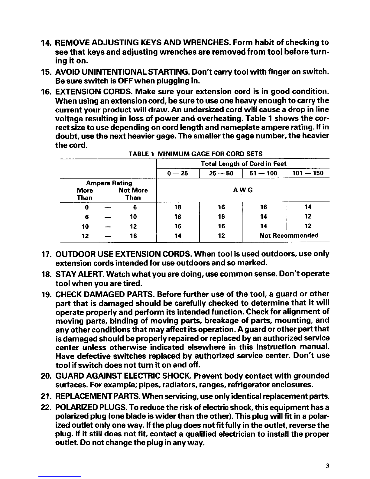
of powerandoverheating.Table
1
showsthecor-
rectsizetousedependingoncordlengthandnameplateampererating.
If
in
doubt, usethenextheaviergage. Thesmallerthegagenumber, theheavier
thecord.
TABLE 1.
MINIMUM
GAGE
FOR
CORD SETS
Total Length
of
Cord in Feet
0-25
I
25-50
I
51-100
I
101-150
Than Than
0-
6
6- 10
10
-
12
12
-
16
Ampere Rating
More NotMore
18 16 16 14
18 16 14 12
16 16 14 12
14 12
Not
Recommended
AWG
17.
OUTDOOR USEEXTENSIONCORDS. Whentoolisusedoutdoors, useonly
extensioncordsintendedfor useoutdoorsand
so
marked.
18.
STAYALERT. Watchwhatyouaredoing, usecommonsense. Don't operate
toolwhenyouaretired.
19.
CHECK DAMAGED PARTS. Beforefurther useof thetool, a guard or other
part
that isdamagedshould becarefully checkedtodetermine
that
it
will
operateproperly andperform itsintendedfunction. Checkfor alignment of
moving parts, binding of moving parts, breakage of parts, mounting, and
anyotherconditionsthatmayaffectitsoperation.A guardorother partthat
isdamagedshouldbeproperlyrepairedorreplacedbyanauthorizedservice
center unless otherwise indicated elsewhere in this instruction manual.
Have defective switches replacedby authorized service center. Don't use
toolifswitchdoesnotturn
it
on
and
off.
20.
GUARDAGAINST ELECTRICSHOCK. Preventbody contact withgrounded
surfaces.Forexample; pipes, radiators, ranges, refrigerator enclosures.
21.
REPIACEMENTPARTS.Whenservicing,useonlyidenticalreplacementparts.
22.
POLARIZEDPLUGS.To reducetheriskofelectricshock, thisequipmenthasa
polarizedplug(onebladeiswider thantheother).Thisplug
will
fit
inapolar-
ized
outletonlyoneway.
H
theplugdoesnotfitfully intheoutlet, reversethe
plug.
H
it
stilldoes notfit, contacta qualifiedelectriciantoinstallthe proper
outlet. Donotchangethepluginany way.
3

VOLTAGEWARNING: Beforeconnectingthetooltoapowersource(receptacle,
outlet, etc.) be sure the voltage supplied isthe same as that specifiedon the
nameplateof thetool. A powersource
with
voltage greaterthan
that
specified
forthetoolcanresultinSERIOUSINJURYtotheuser-as wellasdamagetothe
tool. If
in
doubt, DONOTPLUG
IN
THE
TOOL.
Usingapowersourcewithvoltage
lessthanthenameplateratingisharmfultothemotor.
ADDITIONALSAFETY RULES
1.
Rags, cloth, cord, stringandthelikeshould neverbeleftaroundthework
2. Avoid cutting nails. Inspectfor and remove all nailsfrom theworkpiece
3. Handlethebladesvery carefully.
4.
Besure theblade installation boltsare securely tightenedbefore opera-
5. Holdthetoolfirmlywithbothhands.
6.
Keephandsawayfromrotatingparts.
7.
Beforeusingthetoolonanactualworkpiece, let
it
runforawhile. Watch
for vibrationor wobblingthatcould indicatepoor installation or apoorly
balancedblade.
8.
Makesurethebladeisnotcontactingtheworkpiece beforetheswitchis
turnedon.
9.
Waituntilthebladeattainsfullspeedbeforecutting.
IO.
Keepatleast200
mm
(8")
awayfromthetoolatalltimes.
11.
Always switch
off
and wait for the blades to come to a complete stop
12. Neverstick your finger intothechipchute. Chute may jam whencutting
13.
Do
notleavethetoolrunning. Operatethetoolonlywhen hand-held.
14. When leavingtheplaner, switch
off
andset
it
with
thefrontbase
up
ona
15. Always change bothbladesor covers onthedrum, otherwise theresult-
area.
beforeoperation.
tion.
beforeany adjusting.
dampwood. Cleanoutchips
with
astick.
woodenblock,
so
thatthebladesdonotcontactanything.
ingimbalance
will
causevibrationandshorten toollife.
SAVE THESE INSTRUCTIONS.
4

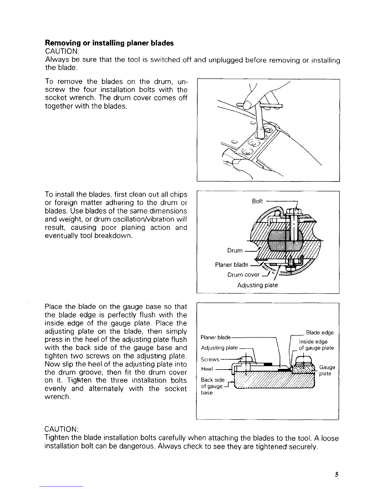
Removing or installingplaner blades
CAUTION:
Always be sure that the tool is switched off and unplugged before removing or installing
the blade.
To
remove the blades on the drum, un-
screw the four installation bolts with the
socket wrench. The drum cover comes off
together withthe blades.
To installthe blades, first clean out all chips
or foreign matter adhering to the drum or
blades. Use blades of the same dimensions
and weight, or drum oscillation/vibration
will
result, causing poor planing action and
eventually tool breakdown.
Place the blade on the gauge base
so
that
the blade edge is perfectly flush with the
inside edge of the gauge plate. Place the
adjusting plate on the blade, then simply
press in the heel of the adjusting plate flush
with the back side of the gauge base and
tighten two screws on the adjusting plate.
Now slip the heel of the adjusting plate into
the drum groove, then fit the drum cover
on
it.
Tigkten the three installation bolts
evenly and alternately with the socket
wrench.
\
I
Bolt
I
Drum
Planer blac
Drum
I
Adjusting plate
I
Adjustingplate
-
\
/
-
of
gaugeplate
I
base
CAUTION:
Tighten the blade installation bolts carefully when attaching the bladesto the tool. A loose
installation bolt can be dangerous. Always check to see they are tightened securely.
5

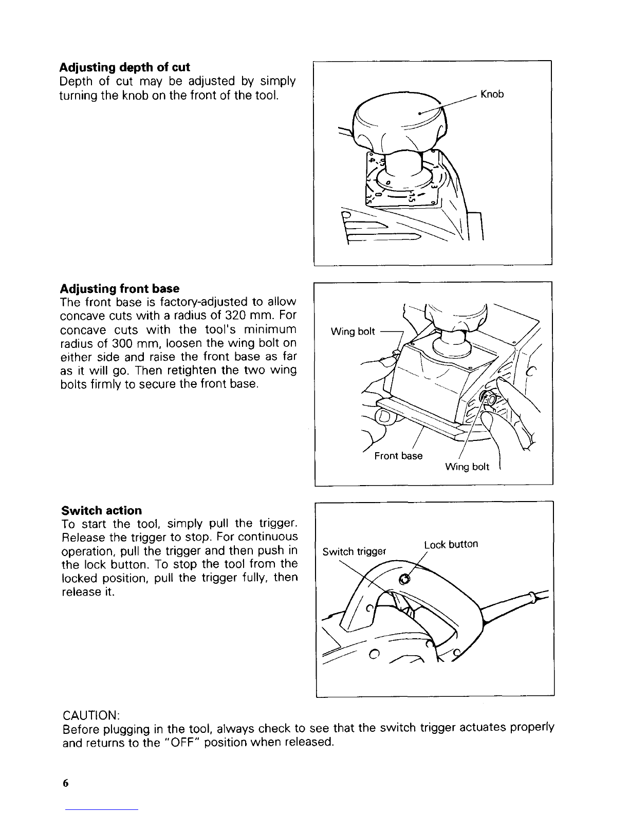
Adjusting depth of cut
Depth
of
cut may be adjusted by simply
turning the knob on the front
of
the tool.
Adjusting front base
The front base is factory-adjusted to allow
concave cuts with
a
radius
of
320
mm. For
concave cuts with the tool’s minimum
radius of
300
mm, loosen the wing bolt on
either side and raise the front base as
far
as it will go. Then retighten the two wing
boltsfirmly to secure the front base.
Switch action
To
start the tool, simply pull the trigger.
Release the trigger to stop. For continuous
operation, pull the trigger and then push in
the lock button. To stop the tool from the
locked position, pull the trigger fully, then
release it.
Knob
1
Wing
bolt
CAUTION:
Before plugging in the tool, always check to see that the switch trigger actuates properly
and returnsto the “OFF” positionwhen released.
6

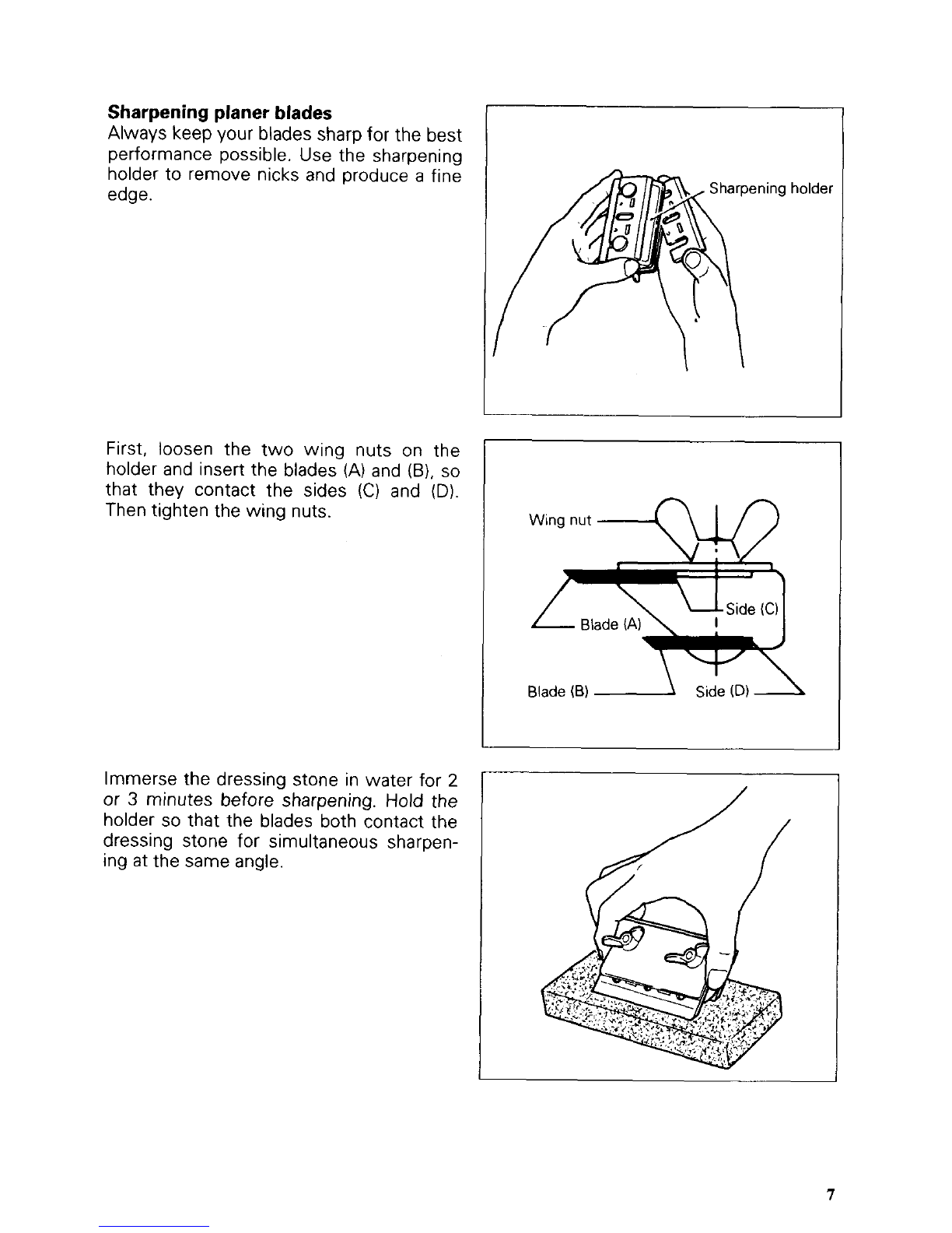
Sharpening planer blades
Always keep your blades sharp
for
the best
performance possible. Use the sharpening
holder to remove nicks and produce
a
fine
edge.
First, loosen the two wing nuts on the
holder and insert the blades (A)and
(B),
so
that they contact the sides
(C)
and
(D).
Then tighten the wing nuts.
Sharpeningholder
Wing nut
Side
(C)
Blade
(A)
Blade
(6)
Immerse the dressing stone in water for
2
or
3
minutes before sharpening.
Hold
the
holder
so
that the blades both contact the
dressing stone
for
simultaneous sharpen-
ing at the same angle.

MAINTENANCE
CAUTl
ON
:
Always be sure that the tool is switched off and unpluggedbefore attempting to perform
inspection or maintenance.
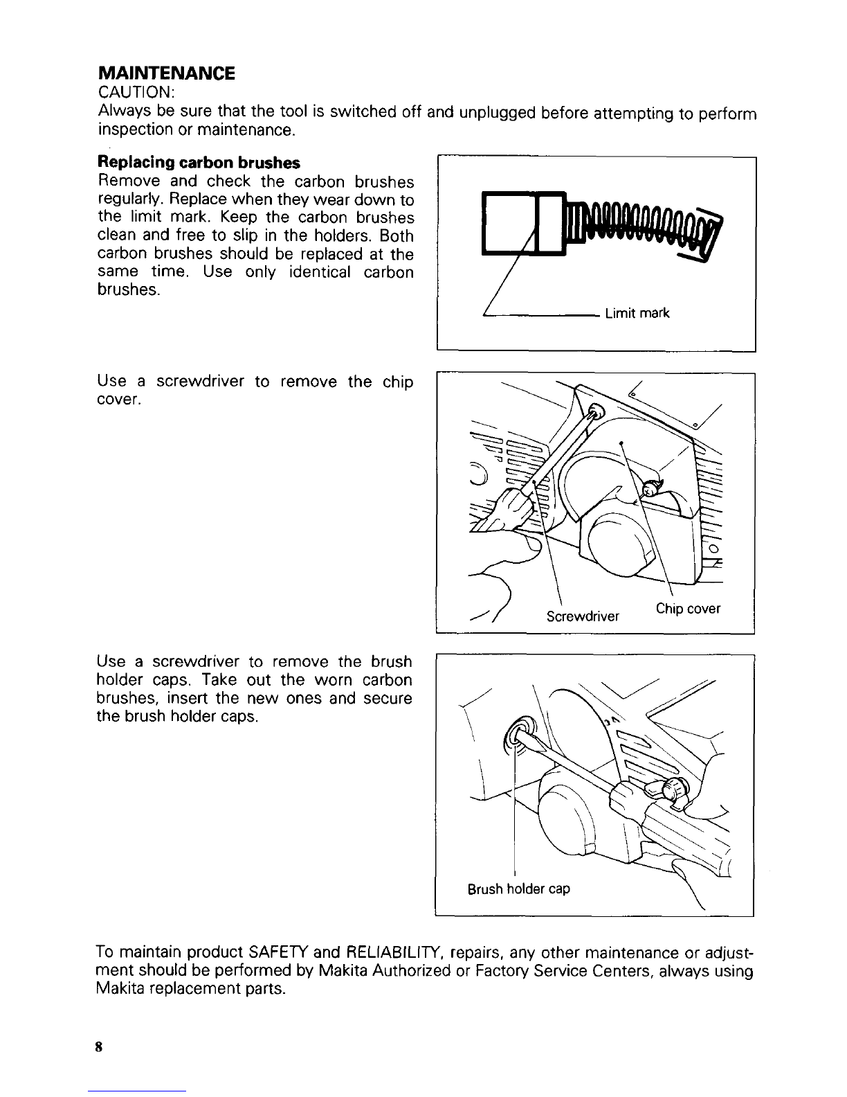
Replacingcarbon brushes
Remove and check the carbon brushes
regularly. Replacewhen they wear down to
the limit mark. Keep the carbon brushes
clean and free to slip in the holders. Both
carbon brushes should be replaced at the
same time. Use only identical carbon
brushes.
I
Limit mark
Use
a
screwdriver to remove the chip
cover.
Use
a
screwdriver to remove the brush
holder caps. Take out the worn carbon
brushes, insert the new ones and secure
the brush holder caps.
1
//
Sdrewdriver
Chipcover
\
I
Brush holder cap
To maintain product SAFETY and RELIABILITY, repairs, any other maintenance or adjust-
ment should be performedby MakitaAuthorizedor Factory Service Centers, always using
Makita replacementparts.
8

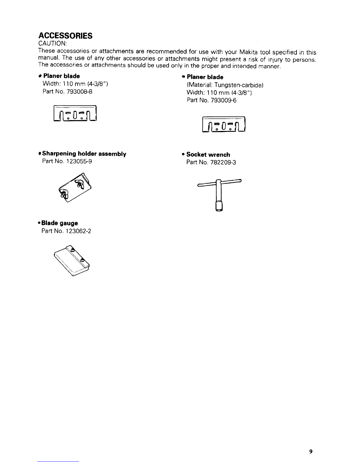
ACCESSORIES
CAUTION
These accessoriesor attachments are recommended for use with your Makita tool specified in this
manual The use
of
any other accessories or attachments might present
a
risk of injury to persons
The accessoriesor attachments should be used only inthe proper and intended manner
Planer blade Planer blade
Width 11
0
mm (4-3/8”)
Part
No
793008-8 (Material Tungsten-carbide)
Width 110mm(4-3/8”)
Part
No
7930096
Sharpening holder assembly
Part
No.
123055-9
*Blade gauge
Part
No.
123062-2
Socketwrench
Part No.782209-3
9

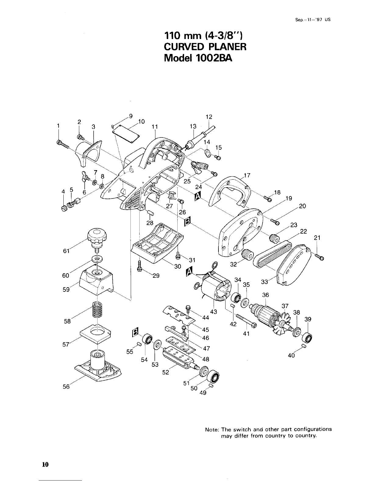
Seo.-ll-'97
US
110
mm
(4-318")
CURVED PLANER
Model
1002BA
e
Note: The switch and other part configurations
may differ from country to country.
10
Altri manuali per 1002BA
4
Indice
Altri manuali Makita Pialla

Makita
Makita 1902 Manuale utente

Makita
Makita DKP140 Manuale utente

Makita
Makita KP0810 Manuale utente

Makita
Makita PLANER 2040 Manuale utente

Makita
Makita 1051D Manuale utente

Makita
Makita BKP140 Manuale utente

Makita
Makita KP0800 Manuale utente

Makita
Makita KP001G Manuale utente

Makita
Makita Maktec MT190 Manuale

Makita
Makita PC1100 Manuale utente

Makita
Makita 1923B Manuale utente

Makita
Makita 1902 Manuale utente

Makita
Makita 1806B Manuale utente

Makita
Makita 1806B Manuale utente

Makita
Makita DKP181 Manuale utente

Makita
Makita DKP181 Manuale utente

Makita
Makita 1050D Manuale utente

Makita
Makita 1923H Manuale utente

Makita
Makita KP0800/2 Manuale utente

Makita
Makita 1100N Manuale utente