
Makita 3704 Manuale utente

GB
Trimmer Instruction Manual
F
Affleureuse Manuel d’Instructions
D
Einhandfräse Betriebsanleitung
I
Rifilatore Istruzioni d’Uso
NL
Kantenfrees Gebruiksaanwijzing
E
Rebordeadora Manual de Instrucciones
P
Tupia Manual de Instruço˜es
DK
Overfræser Brugsanvisning
S
Kantfräs Bruksanvisning
N
Overfres (Kanttrimmer) Bruksanvisning
SF
Viimeistely-yläjyrsin Käyttöohje
GR ƒÔ‡ÙÂÚ (ÎÔ˘ÚÂÙÈÎfi) √‰ËÁ›Â˜ ÃÚ‹Ûˆ˜
3704
3704 (’100. 11. 23)
1 2
3 4
5 6
3
124
5
68
9
7
10
11
12
14
7
13
10
16
15
47
17
18 10
7
7
21
22
21
20
23
19 20
2
3704 (illust) (’100. 11. 23)

8
9 10
11 12
20 24
19
21
25
26
28
27
29
30
27
31 16
30
7
(A)
13 14
32
25
30
29
28
26
27
30
27
26
32
29
25
28
3704 (illust) (’100. 11. 23)
3

15 16
17 18
19 20
32
33
27
35
36
34
31
16
19
37
38
16
7
39
40
21 22
7
41
42
44
7
43
41
45 10 mm
19
4
3704 (illust) (’100. 11. 23)

23 24
25 26
27
46
47
46 10
48
27
46
40
49
50
49
40
50
7
46
40
49
746
50
28
53 54
46
51 52
3704 (illust) (’100. 11. 23)
5

29 30
55
40
56
6
3704 (illust) (’100. 12. 1)

Symbols
The following show the symbols used for the tool. Be sure that you understand their meaning before use.
Symboles
Nous donnons ci-dessous les symboles utilisés pour l’outil. Assurez-vous que vous en avez bien compris la
signification avant d’utiliser l’outil.
Symbole
Die folgenden Symbole werden für die Maschine verwendet. Machen Sie sich vor der Benutzung unbedingt mit
ihrer Bedeutung vertraut.
Symboli
Per questo utensile vengono usati i simboli seguenti. Bisogna capire il loro significato prima di usare l’utensile.
Symbolen
Voor dit gereedschap worden de volgende symbolen gebruikt. Zorg ervoor dat u de betekenis van deze
symbolen begrijpt alvorens het gereedschap te gebruiken.
Símbolos
A continuación se muestran los símbolos utilizados con esta herramienta. Asegúrese de que entiende su
significado antes de usarla.
Símbolos
O seguinte mostra os símbolos utilizados para a ferramenta. Certifique-se de que compreende o seu
significado antes da utilização.
Symboler
Nedenstående symboler er anvendt i forbindelse med denne maskine. Vær sikker på, at De har forstået
symbolernes betydning, før maskinen anvendes.
Symboler
Det följande visar de symboler som används för den här maskinen. Se noga till att du förstår deras innebörd
innan maskinen används.
Symbolene
Følgende viser de symblene som brukes for maskinen. Det er viktig å forstå betydningen av disse før maskinen
tas i bruk.
Symbolit
Alla on esitetty koneessa käytetyt symbolit. Opettele näiden merkitys, ennen kuin käytät konetta.
™‡Ì‚ÔÏ·
∆· ·ÎfiÏÔ˘ı· ‰Â›¯ÓÔ˘Ó Ù· ۇ̂ÔÏ· Ô˘ ¯ÚËÛÈÌÔÔÈÔ‡ÓÙ·È ÁÈ· ÙÔ Ì˯¿ÓËÌ·. µÂ‚·Èˆı›Ù fiÙÈ
ηٷϷ‚·›ÓÂÙ ÙË ÛËÌ·Û›· ÙÔ˘˜ ÚÈÓ ·fi ÙË ¯Ú‹ÛË.
[Read instruction manual.
[Lire le mode d’emploi.
[Bitte Bedienungsanleitung lesen.
[Leggete il manuale di istruzioni.
[Lees de gebruiksaanwijzing.
[Lea el manual de instrucciones.
[Leia o manual de instruço˜es.
[Læs brugsanvisningen.
[Läs bruksanvisningen.
[Les bruksanvisingen.
[Katso käyttöohjeita.
[¢È·‚¿ÛÙ ÙȘ Ô‰ËÁ›Â˜ ¯Ú‹Û˘.
[DOUBLE INSULATION
[DOUBLE ISOLATION
[DOPPELT SCHUTZISOLIERT
[DOPPIO ISOLAMENTO
[DUBBELE ISOLATIE
[DOBLE AISLAMIENTO
[DUPLO ISOLAMENTO
[DOBBELT ISOLERET
[DUBBEL ISOLERING
[DOBBEL ISOLERING
[KAKSINKERTAINEN ERISTYS
[¢π¶§∏ ª√¡ø™∏
3704 (illust) (’100. 12. 1)
7

ENGLISH Explanation of general view
1 Loosen
2 Tighten
3 Hold
4 Wing nut
5 Spring washer
6 Flat washer (small)
7 Base
8 Flat washer (large)
9 Bolt
10 Trimmer shoe
11 Adjusting screw
12 Scale
13 Bit protrusion
14 Nut
15 Graduation
16 Wing bolt
17 Amount of chamfering
18 Switch lever
19 Workpiece
20 Feed direction
21 Bit revolving direction
22 (View from the top of
the tool)
23 Correct bit feed direction
24 Trimmer shoe, straight guide
or trimmer guide
25 Bolt
26 Guide plate
27 Straight guide
28 Flat washer
29 Wave washer
30 Wing nut
31 Clamp screw (A)
32 Center hole
33 Nail
34 Adjusting screw
35 Clamp screw (B)
36 Trimmer guide
37 Bit
38 Guide roller
39 Screws
40 Screwdriver
41 Templet guide
42 Convex portions
43 Straight bit
44 Templet
45 Distance (X)
46 Not available
47 Not available
48 Not available
49 Not available
50 Not available
51 Not available
52 Not available
53 Not available
54 Not available
55 Limit mark
56 Brush holder cap
SPECIFICATIONS
Model 3704
Collet capacity ..................................... 6 mm or 1/4’’
No load speed (min
–1
) ................................... 30,000
Overall length ............................................... 310 mm
Net weight ....................................................... 1.5 kg
•Due to our continuing program of research and
development, the specifications herein are subject
to change without notice.
•Note: Specifications may differ from country to
country.
Power supply
The tool should be connected only to a power supply
of the same voltage as indicated on the nameplate,
and can only be operated on single-phaseAC supply.
They are double-insulated in accordance with Euro-
pean Standard and can, therefore, also be used from
sockets without earth wire.
Safety hints
For your own safety, please refer to the enclosed
safety instructions.
ADDITIONAL SAFETY RULES ENB054-1
1. Hold tool by insulated gripping surfaces when
performing an operation where the cutting
tools may contact hidden wiring or its own
cord. Contact with a ‘‘live’’ wire will make
exposed metal parts of the tool ‘‘live’’ and
shock the operator.
2. Wear hearing protection during extended peri-
ods of operation.
3. Handle the bits very carefully.
4. Check the bit carefully for cracks or damage
before operation. Replace cracked or dam-
aged bit immediately.
5. Avoid cutting nails. Inspect for and remove all
nails from the workpiece before operation.
6. Hold the tool firmly.
7. Keep hands away from rotating parts.
8. Make sure the bit is not contacting the work-
piece before the switch is turned on.
9. Before using the tool on an actual workpiece,
let it run for a while. Watch for vibration or
wobbling that could indicate improperly
installed bit.
10. Be careful of the bit rotating direction and the
feed direction.
11. Do not leave the tool running. Operate the tool
only when hand-held.
12. Always switch off and wait for the bit to come
to a complete stop before removing the tool
from workpiece.
13. Do not touch the bit immediately after opera-
tion; it may be extremely hot and could burn
your skin.
14. Always lead the power supply cord away from
the tool towards the rear.
15. Do not smear the tool base carelessly with
thinner, gasoline, oil or the like. They may
cause cracks in the tool base.
16. Draw attention to the need to use cutters of the
correct shank diamater and suitable for the
speed of the tool.
SAVE THESE INSTRUCTIONS.
8
3704 (E) (’100. 11. 29)

OPERATING INSTRUCTIONS
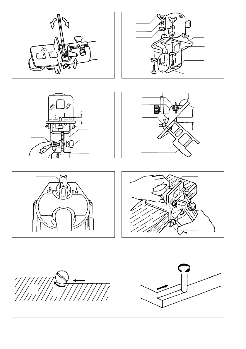
Installing or removing trimmer bit (Fig. 1)
Important:
Always be sure that the tool is switched off and
unplugged before installing or removing the bit.
Insert the bit all the way into the collet cone and
tighten the collet nut securely with the two wrenches.
To remove the bit, follow the installation procedure in
reverse.
CAUTION:
•Do not tighten the collet nut without inserting a bit,
or the collet cone will break.
•Use only the wrenches provided with the tool.
Installing trimmer shoe
(after it has been removed from the tool) (Fig. 2)
NOTE:
The trimmer shoe is factory installed on the tool.
Use the bolts, wing nuts, spring washers and flat
washers to install the trimmer shoe as shown in
Fig. 2.
Adjusting bit protrusion (Fig. 3)
To adjust the bit protrusion, loosen the nut and move
the tool base up or down as desired by turning the
adjusting screw. After adjusting, tighten the nut firmly
to secure the tool base.
Adjusting angle of tool base (Fig. 4)
Loosen the wing bolts and adjust the angle of the tool
base (5° per graduation) to obtain the desired cutting
angle.
Adjusting amount of chamfering
To adjust the amount of chamfering, loosen the wing
nuts and adjust the trimmer shoe.
CAUTION:
With the tool unplugged and switch in the ‘‘OFF’’
position, rotate the collet nut on the tool several times
to be sure that the bit turns freely and does not
contact the base or trimmer shoe in any way.
Switch action (Fig. 5)
To start the tool, move the switch lever to the ‘‘ON’’
position. To stop, move the switch lever to the ‘‘OFF’’
position.
Operation (Fig. 6,7&8)
Turn the tool on without the bit making any contact
with the workpiece and wait until the bit attains full
speed. Then move the tool over the workpiece sur-
face, keeping the tool base and trimmer shoe flush
with the sides of the workpiece.
(Note)
This tool can be used as a conventional trimmer when
you remove the trimmer shoe.
When doing edge cutting, the workpiece surface
should be on the left side of the bit in the feed
direction.
NOTE:
•Moving the tool forward too fast may cause a poor
quality of cut, or damage to the bit or motor. Moving
the tool forward too slowly may burn and mar the
cut. The proper feed rate will depend on the bit size,
the kind of workpiece and depth of cut. Before
beginning the cut on the actual workpiece, it is
advisable to make a sample cut on a piece of scrap
lumber. This will show exactly how the cut will look
as well as enable you to check dimensions.
•When using the trimmer shoe, the straight guide or
the trimmer guide, be sure to keep it on the right
side in the feed direction. This will help to keep it
flush with the side of the workpiece.
CAUTION:
Since excessive cutting may cause overload of the
motor or difficulty in controlling the tool, the depth of
cut should not be more than 3 mm at a pass when
cutting grooves. When you wish to cut grooves more
than 3 mm deep, make several passes with progres-
sively deeper bit settings.
Straight guide (Fig. 9, 10, 11 & 12)
The straight guide is effectively used for straight cuts
when chamfering or grooving.
Attach the guide plate to the straight guide with the
bolt, the wave washer, the flat washer and the wing
nut.
Loosen the wing bolts and secure the tool base
horizontally. Attach the straight guide with the clamp
screw (A). Loosen the wing nut on the straight guide
and adjust the distance between the bit and the
straight guide. At the desired distance, tighten the
wing nut securely.
When cutting, move the tool with the straight guide
flush with the side of the workpiece.
If the distance (A) between the side of the workpiece
and the cutting position is too wide for the straight
guide, or if the side of the workpiece is not straight,
the straight guide cannot be used. In this case, firmly
clamp a straight board to the workpiece and use it as
a guide against the trimmer base. Feed the tool in the
direction of the arrow.
3704 (E) (’100. 12. 4)
9

Circular work (Fig. 13, 14 & 15)
•Circular work may be accomplished if you assemble
the straight guide and guide plate as shown in
Fig. 13 or 14.
Fig. 13 for cutting circles between 70 mm and
121 mm in radius.
Fig. 14 for cutting circles between 121 mm and
221 mm in radius.
Note:
Circles between 172 mm and 186 mm in radius
cannot be cut using this guide.
•Min. and max. radius of circles to be cut (distance
between the center of circle and the center of bit)
are as follows:
Min.: 70 mm
Max.: 221 mm
Align the center hole in the straight guide with the
center of the circle to be cut. Drive a nail less than
6 mm in diameter into the center hole to secure the
straight guide. Pivot the tool around the nail in clock-
wise direction.
Trimmer guide (Fig. 16, 17 & 18)
Trimming, curved cuts in veneers for furniture and the
like can be done easily with the trimmer guide. The
guide roller rides the curve and assures a fine cut.
Loosen the wing bolts and secure the tool base
horizontally. Install the trimmer guide on the tool base
with the clamp screw (A). Loosen the clamp screw (B)
and adjust the distance between the bit and the
trimmer guide by turning the adjusting screw (1 mm
per turn). At the desired distance, tighten the clamp
screw (B) to secure the trimmer guide in place.
When cutting, move the tool with the guide roller
riding the side of the workpiece.
Templet guide (Fig. 19, 20, 21 & 22)
The templet guide provides a sleeve through which the bit passes, allowing use of the trimmer with templet
patterns.
Remove the tool base from the tool. Loosen the wing bolts and secure the tool base horizontally. Loosen the
two screws on the tool base.
Place the templet guide on the tool base. There are four convex portions on the templet guide. Secure two of
the four convex portions using the two screws. Install the tool base on the tool.
Secure the templet to the workpiece. Place the tool on the templet and move the tool with the templet guide
sliding along the side of the templet.
NOTE:
The workpiece will be cut a slightly different size from the templet.Allow for the distance (X) between the router
bit and the outside of the templet guide. The distance (X) can be calculated by using the following equation:
Distance (X) = outside diameter of the templet guide – router bit diameter
2
MAINTENANCE
CAUTION:
Always be sure that the tool is switched off and
unplugged before carrying out any work on the tool.
Replacement of carbon brushes (Fig. 29 & 30)
Replace carbon brushes when they are worn down to
the limit mark. Both identical carbon brushes should
be replaced at the same time.
To maintain product safety and reliability, repairs,
maintenance or adjustment should be carried out by a
Makita Authorized Service Center.
ACCESSORY
Makita offers an extensive range of trimmer bits which
comply with the latest safety regulations. Specifica-
tions of each type can be found on the following
pages.
10
3704 (E) (’100. 12. 1)
Indice
Lingue:
Altri manuali Makita Tagliabordi

Makita
Makita UR008GD201 Manuale utente

Makita
Makita RBC221 Manuale utente

Makita
Makita DUR368L Manuale utente

Makita
Makita DRT50 Manuale utente

Makita
Makita DUH481 Manuale utente

Makita
Makita DUN461W Manuale utente

Makita
Makita RBC2510 Manuale utente

Makita
Makita 3703 Manuale utente

Makita
Makita RBC225 Guida utente

Makita
Makita DUH523 Manuale utente

Makita
Makita DUR187URF Manuale utente

Makita
Makita DUR188UZ Manuale utente

Makita
Makita DRT50ZX06 Manuale utente

Makita
Makita BBC231U Manuale utente

Makita
Makita DUR190U Manuale utente

Makita
Makita RT001G Manuale utente

Makita
Makita UH013G Manuale utente

Makita
Makita DUR187U Manuale utente

Makita
Makita RT0700C Manuale utente

Makita
Makita EH561 Manuale utente


