makro RACER Manuale utente

READ CAREFULLY BEFORE OPERATING THE DEVICE!
LEGAL DISCLAIMERS
Comply with the laws and regulations in force within the area while using the device.
Do not use the device in protected or archeological sites and military zones. Notify
any historical and cultural artifacts you find to the concerned authorities.
WARNINGS
RACER is a state-of-the-art electronic device. Do not assemble or operate the device
before reading the user manual.
Do not keep the device and search coil under extremely low and high temperatures
for extended periods. (Storage Temperature: 0°C to 40°C / 32°F to 104°F)
Do not immerse the device and its accessories (except for the search coil) in water or
keep them in excessively humid environments.
Protect the device against impacts that may occur during shipping in particular.
RACER may only be disassembled and repaired by authorized service centers.
Disassembling the device for any reason voids the warranty.

Table of Contents
Assembly .................................................................................................................................................................
General Description of the Device ................................................................................
Battery Details ................................................................................................................................................
Display.........................................................................................................................................................................
Correct Use...........................................................................................................................................................
Quick Guide.........................................................................................................................................................
Menu........................................................................................................................................................................
Modes.............................................................................................................................................................
Ground Balance...............................................................................................................................
Gain and Threshold..............................................................................................................................
Target ID and ID Filtering.................................................................................................
Pinpoint...................................................................................................................................................................
Target Distance..........................................................................................................................................
Swinging Speed and Target Identification....................................................
Large or Near-Surface Targets...........................................................................................
False Signals and Reasons........................................................................................................
Magnetic Mineralization Indicator.............................................................................
Rocks and Searching in Rocky Terrains.....................................................
Tracking and Effects of Rocks.............................................................................................
Metals Under Rocks.................................................................................................................
Searching in Shallow Water and Beach..............................................................
Messages.............................................................................................................................................................
Technical Specifications..............................................................................................................
1
2
3
4
5
6
7-9
10-11
12-15
16
17-18
19
20
20
20
20
21
21-22
22
22-23
23
24
25
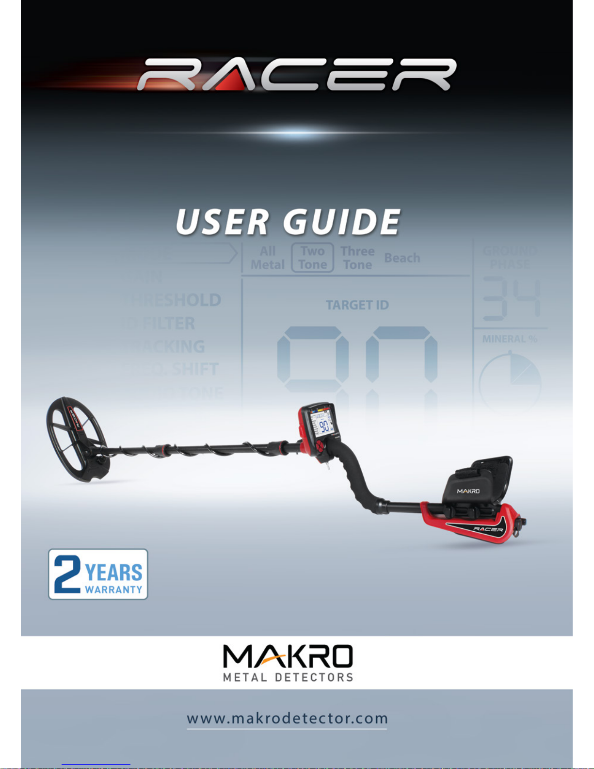
Insert the washers as shown on the telescopic shaft. Install the telescopic shaft to its location
on the search coil. Secure by tightening the screw and nut.
Loosen the twist lock before mounting the telescopic shaft to the upper rod. Press down the pin
and engage the pieces together and tighten the twist lock after the pin is clicked into the hole.Wind
the cable of the search coil on the telescopic shaft without stretching too much. Plug the connector
on the cable to the search coil input socket on the system box and secure by tightening the nut.
Loosen the twist lock of the telescopic shaft to extend or shorten it. Adjust the length of the
shaft by keeping the pin located on the rear pressed down and clicking the pin in any of the
holes. Secure by tightening the twist lock.
Insert the armrest band through its slot as shown in the figure. Loosen the screws and adjust
the armrest position to your comfort by sliding it down or up and secure by tightening the
screws.
1
2
3
4
Assembly Page_1
1
3
2
4
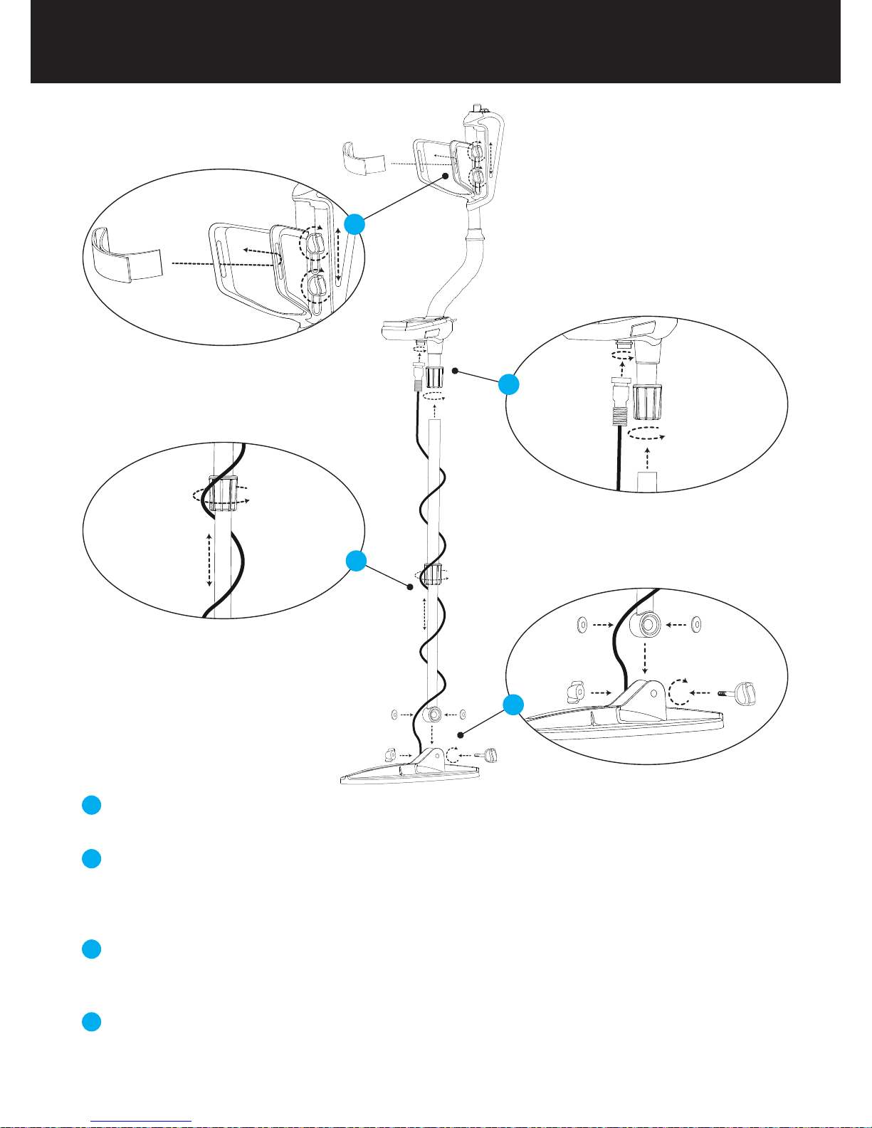
Display showing all settings and information
Bluetooth headphone module jack (Bluetooth headphone is sold separately)
Keypad for navigation among menu options and changing the device settings
Ground balance and pinpoint trigger
Speaker
Battery compartment cover
On /Off and volume adjustment button
Wired headphone jack
Search coil connector socket
LED flashlight
1
2
3
4
5
6
7
8
9
10
1
2
3
4
5
6
7
8
9
10
General Description of the Device
Page_2

The device is supplied with 4 pieces of AA Alkaline batteries.
To remove the battery compartment cover, press on the latch and pull out. Insert the batteries
observing correct polarity of + (plus) and - (minus).
The device can be used for approximately 25-30 hours when the batteries are fully charged.
Operating time of other brands and types of batteries available on the market may vary.
AA Alkaline batteries are recommended for the best performance. Good quality Ni-MH
rechargeable batteries can be used, too. Rechargeable batteries with high mAh (capacity)
ratings oer extended operating times than batteries with lower rating. We recommend use of
minimum 2500mAh batteries.
Low Battery Level
Battery icon on the display shows the battery life status. When the charge decreases, the bars
inside the battery icon decrease, too. "Lo" message appears on the display when the batteries
are depleted and the device shuts down after a short period.
Battery Details Page_3
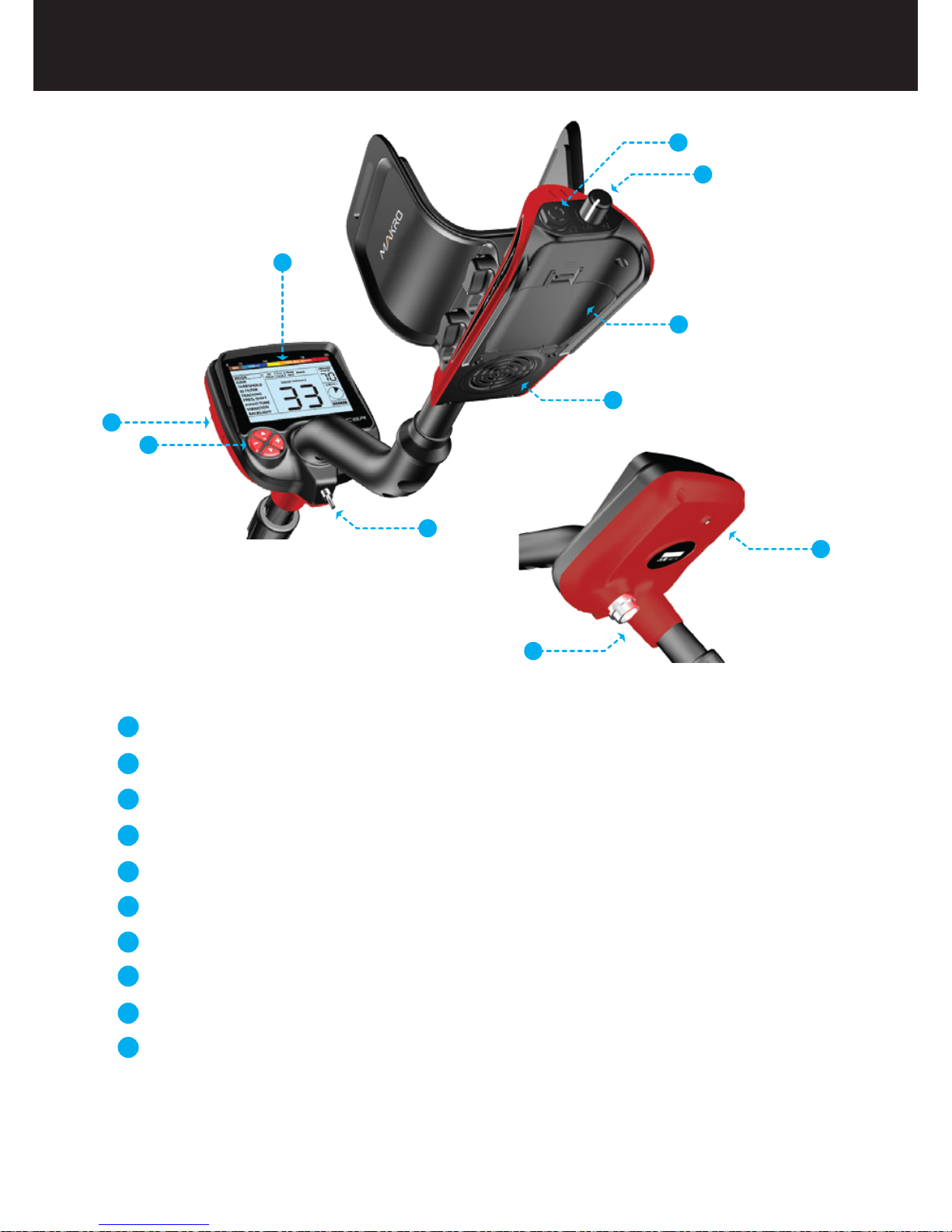
Menu providing access to all settings of the device.
Target ID and color scale.
Cursor indicating the ID of the detected target and its position on the color
scale. It is displayed by itself when the target signal is weak and in a black
box when the signal is strong.
Search mode indicator.
Section which shows the Target ID during search, the ground balance value
during ground balance adjustment and the estimated target depth during
the pinpoint process. Also, the numeric value of any setting selected from
the menu is displayed in this field.
Section which shows the fine tuning value during ground balance
adjustment and current ground balance value during search.
Magnetic mineralization indicator.
Battery level indicator.
Tracking on / off status indicator.
Section which shows the warning messages.
1
3
4
5
6
7
8
9
10
2 4 5 3
6
7
8
9
10
2
1
Display
Page_4
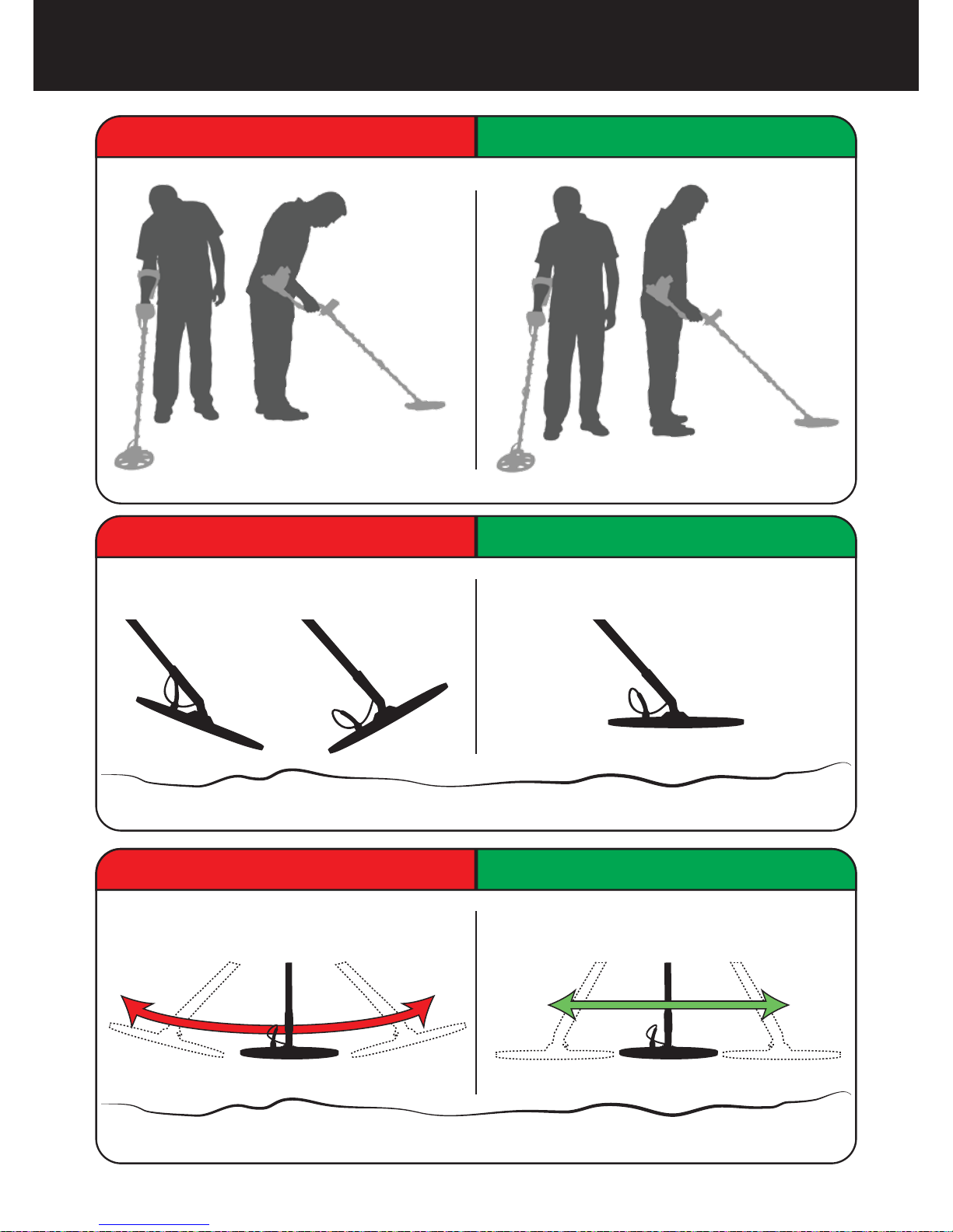
Incorrect Handling Correct Handling
Incorrect Use Correct Use
Incorrect Use Correct Use
Correct Use Page_5

Assemble the device as per the instructions on page 1.
Insert the batteries by paying attention to +/- polarity.
Rotate the on/off switch located behind the device clockwise to turn on the
device. This switch also adjusts the volume.
When the device is turned on, it will start in the Two Tone mode. You can
change the mode based on the area that you are searching. For instance, if
your search will be performed on wet beach sand, select the Beach mode.
To ground balance, push and hold the trigger forward and pump the search
coil up and down 3cm (1.2'') above the ground until a “beep” sound is heard.
You can increase the GAIN if needed. Increasing the gain will offer you
greater depth. However, if the surroundings or the ground cause excessive
noise in the device, you need to lower the gain setting.
Testing with various metals is useful for getting familiar with the sounds
produced by the device.
Based on the IDs of the metals you don't want to detect, you can set the ID
FILTER and ignore those metals. For instance, if you don’t want to detect
ferrous metals with 20 ID, you can adjust the ID FILTER to 21.
You can now start searching.
Since your device operates with the motion principle, swing the search coil
right and left maintaining 5cm (2") distance above the ground. If the search
coil does not move, the device will not provide any warning tones even if
the coil is over a metal target.
When a target is detected, the ID of the target is displayed on the screen
and the cursor indicates its position in the ID and color scale. The device
also produces a warning tone based on the search mode selected.
Upon target detection, you can pinpoint the exact location of the target by
pulling and holding the trigger back.
1
3
4
5
6
7
8
9
10
11
12
2
Quick Guide
Page_6
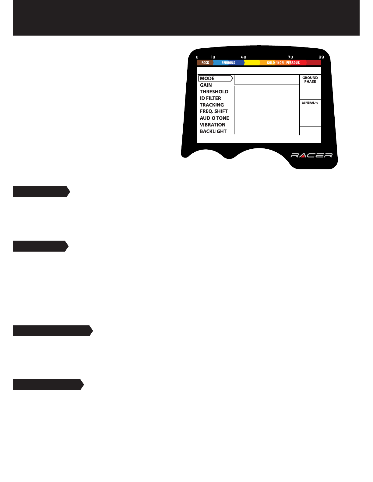
MODE
4 search modes adapted to different ground conditions and target types are offered by RACER.
Names of the search modes are defined as All Metal, Two Tone, Three Tone and Beach on the
menu screen. You can easily switch between the modes by using the direction keys during your
search. See MODES for more details (page 10-11).
Select a setting from the menu by using the
up/down buttons. The value of the selected
setting is shown on the display. You can
change the value by using the + and -
buttons.
If up/down and +/- buttons are kept
pressed for a certain period, options and
values change more rapidly.
If no button is pressed for a while after
selecting a setting or changing its value, the
device automatically returns to MODE option.
Pulling the trigger enables to return to the
MODE option without waiting.
GAIN
It is the depth setting of the device. It is also used to eliminate the ambient electromagnetic
signals from the surrounding environment and noise signals transmitted from ground.
Gain setting range is 01-99 and pre-defined for each mode. All modes start at default settings.
They can be manually modified when necessary. Gain adjustment applies to the selected mode;
the modified setting does not affect the gain setting of the other modes.
For more details, please read GAIN AND THRESHOLD on page 16.
THRESHOLD
This setting is used to adjust the humming sound, referred to as the threshold sound, which is
continuously heard in the background in the All Metal mode. It is used to increase the target
signal, in other words, the depth of the device. For more details, please refer to the section titled
GAIN AND THRESHOLD (page 16).
ID FILTER
TARGET ID is the number produced by the metal detector based on the conductivity of the
metals and gives an idea to the user about what the target may be. Target ID is shown with two
digits on the display and ranges between 01-99.
ID FILTER is the ability of the device to ignore unwanted metals. In other words, the detector will
not provide a warning tone or a target ID when such metals are detected. It provides ease of use
by rejecting mineralized rocks (hot rocks) and metals such as iron and foil.
Menu Page_7
Indice
Altri manuali makro Rilevatore di metalli


Manuali Rilevatore di metalli popolari di altre marche


Steinberg Systems
Steinberg Systems SBS-MD-12 Manuale utente

GOLDEN MASK
GOLDEN MASK 5 Manuale utente

Grizzly
Grizzly YM 203 Manuale utente

Fisher Research Labs
Fisher Research Labs 1280-X Aquanaut Manuale utente

Treasure Cove
Treasure Cove Vibra-Probe 560 Manuale utente

Accurate Locators
Accurate Locators XL16 IMAGER Manuale utente