
Malta Dynamics C7002-G2 Manuale utente

User Instruction Manual
MaltaDynamics.com | +1-800-494-1840
2
OSHAOSHA
COMPLIANT
O
C
C
U
P
A
T
I
O
N
A
L
S
A
F
E
T
Y
A
N
D
H
E
A
L
T
H
A
D
M
I
N
I
S
T
R
A
T
I
O
N
M
A
L
T
A
D
Y
N
A
M
I
C
S
.
C
O
M
ANSI
M
A
L
T
A
D
Y
N
A
M
I
C
S
.
C
O
M
ANSIANSI
A
M
E
R
I
C
A
N
N
A
T
I
O
N
A
L
S
T
A
N
D
A
R
D
S
I
N
S
T
I
T
U
T
E
Z359.14-2021
Self-Retracting Lifeline (SRL) INSTRUCTION
MANUAL
These instructions apply to the following model(s):
C7002-G2 - 50' Warthog SRL With Snap Hook Class 1
C7102-G2 - 6' Pygmy hog SRL With Snap Hook Class 1
C7104-G2 - 6' Pygmy hog SRL With Rebar Hook Class 1
C7201-G2 - 11' Pygmy hog SRL With Snap Hook Class 1
C7203-G2 - 11' Pygmy hog SRL With Rebar Hook Class 1
C8000-G2 - 20' Razorback SRL With Snap Hook Class 1
C8001-G2 - 30' Razorback SRL With Snap Hook Class 1
C9000-G2 - 20' Hybrid Hog SRL With Snap Hook Class 1
C9001-G2 - 30' Hybrid Hog SRL With Snap Hook Class 1
LE3261 - 6' Edge Hog SRL With Snap Hook Class 2
LE3261D - 6' Dual Edge Hog SRL With Snap Hooks Class 2
LE3263 - 6' Edge Hog SRL With Rebar Hook Class 2
LE3263D- 6' Dual Edge Hog SRL With Rebar Hooks Class 2
LE3311 - 10' Edge Hog SRL With Snap Hook Class 2
LE3311D - 10' Dual Edge Hog SRL With Snap Hooks Class 2
LE3313 - 10' Edge Hog SRL With Rebar Hook Class 2
LE3313D - 10' Dual Edge Hog SRL With Rebar Hooks Class 2
LE7020 - G2 - 20' Edge Hog SRL With Snap Hook Class 2
LE7030 - G2 - 30' Edge Hog SRL With Snap Hook Class 2
LE7050 - G2 - 50' Edge Hog SRL With Snap Hook Class 2
A copy of this manual must be available to users at all times. Visit
www.MaltaDynamics.com for the latest user instruction manual based upon date of
manufacture.
Manual Revision Code:
MD-20230508

3
MaltaDynamics.com | 800-494-1840
Visit www.MaltaDynamics.com for the latest user
instruction manual based upon date of manufacture.
TABLE OF CONTENTS
C7203-G2 -------------------------------------------------------------- 26
About the Pygmy Hog SRD with C1004 ------------------------ 26
Single Housing End Attached To The Full Body Harness ----- 27
Single Housing End Attached to the Anchorage --------------- 28
Twin-leg SRDs ---------------------------------------------------- 29
Twin-leg SRD Work Zone Transition ------------------------------ 32
Product Labels --------------------------------------------------------- 33
Inspection Log ---------------------------------------------------------- 40
Warranty ---------------------------------------------------------------- 41
Under Penalty of Law ------------------------------------------------- 5
Materials and Construction ------------------------------------------- 5
Purpose ----------------------------------------------------------------- 6
Instructions for Use ---------------------------------------------------- 6
Limitations for Use ----------------------------------------------------- 8
Connector Compatibility Limitations --------------------------------- 10
Connecting Component Limitations --------------------------------- 11
Performance ----------------------------------------------------------- 12
Training ----------------------------------------------------------------- 14
Inspection -------------------------------------------------------------- 14
Cleaning and Maintenance ------------------------------------------- 16
Fall Clearance and Swing Falls --------------------------------------- 17
Class 2 or Below D-Ring ---------------------------------------------- 20
Fall Clearance Requirements ------------------------------------------ 25
Single & Twin Connections for C7102-G2, C7104-G2, C7201-G2,
Install the C1004 ------------------------------------------------- 30

MaltaDynamics.com | 800-494-1840
Manual Revision Code:
MD-PHRSRLUIM 11-23-18
4

MaltaDynamics.com | 800-494-1840
5
UNDER PENALTY OF LAW
This manual must be read and understood in its entirety and used as part of
your fall protection training program as required by OSHA 1926 and State and
local regulatory agencies. This instruction manual is intended to meet
industry standards required by and ANSI Z359.14-2021 and should be used as
part of an Employee Fall Safety training program as required by OSHA. User
must read and fully understand the limitations and proper use of the equipment,
and be properly trained by employer prior to use per OSHA 29 CFR 1910.66, 29
CFR 1926.503, and applicable local standards. NOTE: This User Instruction
Manual is not to be removed except by the user of this equipment. Current
User Instruction Manual must always be available to the user. Read and
understand these instructions before using equipment. Do not discard
these instructions.
WARNING
MATERIALS AND CONSTRUCTION
Webbing Materials
• Constructed with UHMWPE with polyester (.770” width; .063”
thickness); breaking strength > 5,000 lbs tensile strength
Cable Materials for
• 7X19 Galvanized Steel (3/16” diameter)
Connector Materials
• Stainless Steel and Alloy Steel
Housing Materials
• Aluminum
• High-Impact Resistant Polymer
Misuse or failure to follow warnings, instructions and limitations
on the use of this equipment may result in serious personal injury
or death. For further instructions about proper use, refer to
supervisor or contact Malta Dynamics at 1-800-494-1840
WARNING
Manual Revision Code:
MD-20230508

6
MaltaDynamics.com | 800-494-1840
Visit www.MaltaDynamics.com for the latest user
instruction manual based upon date of manufacture.
PURPOSE
Malta Dynamics Self-Retracting Lifelines are devices used to safely expand the
working area where a harness with a six-foot lanyard is not adequate. A Self-
Retracting Device (SRD) such as a self-retracting lifeline, is designed to reduce
the shock load to the body of a worker by limiting the distance of a fall. The SRD
allows complete freedom of movement. An SRD is one component of a Personal
Fall Arrest System (PFAS). PFAS normally include a full body harness, anchorage
connector (such as a carabiner and an SRD.)
The Self-Retracting Lifeline (SRL) may be used in a stationary or mobile manner. As
a stationary device, the SRL should be mounted to an approved, fixed anchorage
connector overhead. The SRL extends as the user moves away from the anchor
point, and retracts as the user moves back toward the anchorage point. An SRL
used in a mobile manner should travel on a steel cable, rope or fixed rail, traveling
from one anchorage connector to another.
Self-Retracting Lifelines may include a swivel eye anchorage, self-locking swivel
snap hook or universal rebar hook with impact indicator and 3/16” wire cable or
webbing, carabiner and tag line.
INSTRUCTIONS FOR USE
Do not alter or intentionally misuse this equipment.
WARNING
WARNING
WARNING
•Personal Fall Arrest System (PFAS) MUST limit maximum arrest forces
to 1800 lbs. (8kN) or less.
•Employees shall be trained in accordance with the requirements of
OSHA 29 CFR 1910.66 in the safe use of the system and its components
before using a PFAS.
•Inspect all Personal Fall Arrest System equipment for wear, damage,
and other deterioration prior to each use. Remove defective equipment
from service immediately.
•Thoroughly evaluate and plan all elements of Fall Protection System(s)
before using this equipment. Make sure that your Personal Fall
WARNING
WARNING
MaltaDynamics.com | 800-494-1840
7
Arrest System is appropriate for your needs and facility. Calculate fall
clearance and swing fall clearance. The amount of clearance required is
dependent on the type of connecting subsystem, the anchorage location,
and other factors. When calculating distance, be sure to consider:
• Deceleration Distance
• Movement of harness attachment (D-ring)
• Free Fall Distance
• Height of the worker (how tall is the worker?)
• Elevation of Anchorage Connector
• Connecting Subsystems length
• D-ring connector length
• Length of Full Body Harness stretch
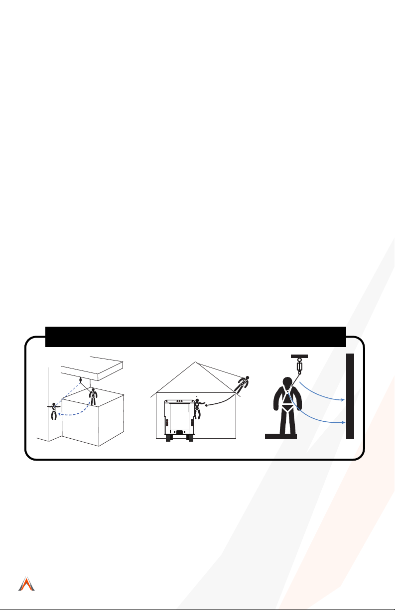
•Swing falls
•Swing falls occur when the anchorage point is not directly above the
point where a fall occurs. The force of striking an object in a swing fall
may cause serious injury or death. Minimize potential for swing falls
by working as close to the anchorage point as possible. Do not permit
a swing fall if injury could occur. Swing falls significantly increase the
amount of clearance required. See Illustration 1.
Illustration 1: Examples of Swing Fall Hazards
•Users must have a written rescue plan and the means to implement
it. This plan must provide prompt employee rescue or assure that
employees have the ability to rescue themselves in the event of a fall.
•Store this equipment in a cool, dry, and clean environment that is out of
direct light when not in use to prevent UV degradation.
•This equipment must be removed from service immediately if a fall is
incurred.
• PInspect all Personal Fall Arrest System equipment for wear, damage, and other deterioration prior to each use.
Remove defective equipment from service immediately.
• Thoroughly evaluate and plan all elements of Fall Protection System(s) before using this equipment. Make sure
that your Personal Fall
Manual Revision Code:
MD-20230508

8
MaltaDynamics.com | 800-494-1840
Visit www.MaltaDynamics.com for the latest user
instruction manual based upon date of manufacture.
LIMITATIONS FOR USE
Do not use this equipment if you are unable to tolerate the
impact of a fallarrest. Age and fitness can seriously affect your
ability to withstand a fall. Consult with a physician if in doubt.
Minors, pregnant women, and anyone with a history of back
and/or neckproblems must not use this equipment.
WARNING
WARNING
WARNING
WARNING
WARNING
• Do not allow the line constituent to retract into the unit in an uncontrolled
manner.
• Malta Dynamics self-retracting lanyards must be used with a full body
harness and shall only be used as a personal fall arrest system that
limits the maximum free fall distance to 2 feet unless unless using a
Class 2 device in which free fall should be limited to 6ft or less.
• Use only with compatible components of subsystems. Substitutions
or replacements made with non-approved components or subsystems
may jeopardize compatibility of equipment and may affect the safety
and reliability of the complete system.
• Not all fall protection components are rated for the same user weight
capacity. Users must be within each component capacity range.
• Self-Retracting Lifelines are designed for a single user with combined
weight - including clothing, tools, etc. - within ANSI rated weight
capacity range of 130 lbs. to 310 lbs.
• This equipment is designed to be used in temperatures ranging from
-40°F to +130°F(-40°C - +54°C).
• Use only with structures capable of supporting static loads required
for Personal Fall Arrest Systems (PFAS). Anchorages used for PFAS
must be capable of sustaining static loads in the direction permitted
by the PFAS of at least: 3,600 lbs. with certification of a qualified
person; or 5,000 lbs. without certification. When more than one
PFAS is attached to an anchorage, the strengths stated above
must be met independently at and for each anchorage location.
Use caution when employing this equipment around machines,
electrical hazards, chemical hazards and sharp edges or
abrasive surfaces, as contact may cause equipment failure,
personal injury, or death.

MaltaDynamics.com | 800-494-1840
Manual Revision Code:
MD-PHRSRLUIM 11-23-18
• Do not expose this equipment to chemicals or harsh solutions that may
have a harmful effect.
• User must not use or install equipment before receiving proper training
from a Competent Person, as defined by OSHA 29 CFR 1926.32(f).
• Only Malta Dynamics shall make repairs or alterations to the equipment.
• All synthetic material must be protected from slag, hot sparks, open
flames, or other heat sources. The use of heat resistant materials is
recommended in these applications.
RESCUE (R0003-G2)
•Capcaity when used for rescue: 1 person
•Force required to operate rescue features when loaded to capacity: 75 lbs
Prevent Slack in line while in rescue mode.
WARNING
RECOVERY SYSTEM OPERATION:
1. Pull outward on the locking pin and hold.
2. Pull outward on the ratchet handle until it stops. Release the pin so that it
falls into the locking position.
3. While maintaining outward tension on the cable, rotate the crank handle
clockwise (cw) to draw the cable into the housing.
Note: to engage the recovery system, it may be necessary to rotate the crank
slightly.
FOR LOWERING:
1. Rotate crank handle in counter clockwise (ccw) direction.
2. If a fall has been arrested and lowering is required, first crank in the
upward direction (cw) for one half rotation, then reverse the direction
(ccw) to begin lowering.
A minimum of 75 lbs. (34kg) is required for lowering.
9

MaltaDynamics.com | 800-494-1840
10
CONNECTOR COMPATIBILITY LIMITATIONS
Malta Dynamics equipment must be coupled only to compatible connectors that
are suitable to your application. Ensure all connections are compatible in size,
shape and strength. Ensure all connectors are fully closed and locked. OSHA 29
CFR 1926.502 prohibits the use of snap hooks to engage to objects unless the
following requirements are met:
• Snap hook must be a locking type snap hook.
•Snap hook must be explicitly designed for such a connection. “Designed
for” means that the manufacturer of the snap hook specifically created
the snap hook to be used to connect to the equipment in question.
Use of a non-locking snap hook can result in rollout (a process by which a snap
hook or carabiner unintentionally disengages from another connector or object
to which it is coupled. Malta Dynamics connectors (snap hooks and carabiners)
are designed to be used only as specified in each product’s user’s instructions.
Avoid the following types of connections:
• Connection of two (or more) snap hooks or carabiners to one D-ring.
• Connection of a snap hook back to its integral lanyard.
• Direct connection of a snap hook to horizontal lifeline.
• Connection in a manner that results in a load on the gate. NOTE: Large
throat opening snap hooks should not be connected to standard size
D-rings or similar objects, as such use will result in a load on the gate if the
hook or D-ring twists or rotates. Large throat snap hooks are designed
for use on structural elements such as rebar or cross members that are
not shaped in such a way that they may capture the gate of the hook.
Manual Revision Code:
MD-20230508
• False engagement connections, where protruding features of the
snap hook or carabiner may catch on the anchor and seem to be fully
engaged to the anchor point. Always confirm engagement.
• Connection to snap hooks or carabiners.
• Direct connection to webbing lanyard, webbing loop, rope lanyard
or tie-back (unless the manufacturer’s instructions for both the
lanyard and connector specifically allow such a connection).
Questo manuale è adatto per i seguenti modelli
19
Indice
Altri manuali Malta Dynamics Attrezzatura di sicurezza

Malta Dynamics
Malta Dynamics A6317 Manuale utente

Malta Dynamics
Malta Dynamics B2000 Manuale utente

Malta Dynamics
Malta Dynamics HLL3001 Manuale utente

Malta Dynamics
Malta Dynamics A7400 Guida

Malta Dynamics
Malta Dynamics A6104 Manuale utente

Malta Dynamics
Malta Dynamics C1006 Manuale utente

Malta Dynamics
Malta Dynamics A6303 Manuale utente

Malta Dynamics
Malta Dynamics X Series Manuale utente

Malta Dynamics
Malta Dynamics Lanyards Manuale utente

Malta Dynamics
Malta Dynamics A6205 Guida


