
Market Forge Industries M24E Guida rapida

EFFECTIVE SEPTEMBER 2, 2014
M24E & M36E
ELECTRICALLY OPERATED BOILERS
PARTS AND SERVICE MANUAL
MARKET FORGE
Telephone: (802) 658-6600 Fax: (802) 860-3732
www.marketforge.com
P/N 14-0310 Rev A (9/14)
Superseding All Previous Parts Lists.
The Company reserves the right to make substitution in the event that items specied are not available.
ERRORS: Descriptive and/or typographic errors are subject to correction.

SEPTEMBER 2, 2014 2 M24E & M36E ELECTRIC BOILERS
TABLE OF CONTENTS
GENERAL TROUBLESHOOTING .......................................................3
PRESSURE ADJUSTMENT.............................................................5
WATER CONTROL BOARD TESTING PROCEDURE .....................................6
WIRING DIAGRAMS
NEW GENERATION ELECTRIC BOILERS ...............................................8
18 KW, 24 KW ....................................................................... 10
36 KW, 42 KW, 48 KW ................................................................ 12
36 KW, 48 KW ....................................................................... 13
ILLUSTRATED PARTS LIST
24" BOILER BASE ................................................................... 14
PRESSURE SWITCH BOX, WITHOUT COVER......................................... 15
CONTROL BOX ASEMBLY, WITH & WITHOUT COVER ................................. 16
ELECTRIC BOILER, LEFT SIDE VIEW – 36” ........................................... 17
ELECTRIC BOILER, FRONT VIEW – 36”............................................... 18
ELECTRIC BOILER, CONTACTOR BOX ............................................... 19
ELECTRIC BOILER, ELEMENTS...................................................... 20

SEPTEMBER 2, 2014 3 M24E & M36E ELECTRIC BOILERS
GENERAL TROUBLESHOOTING
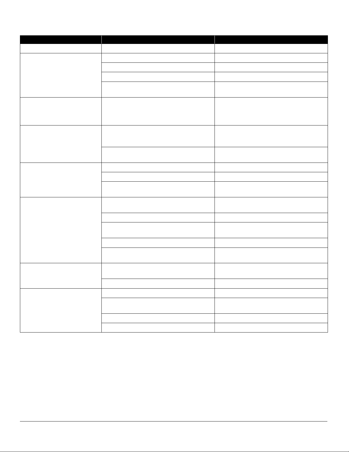
TROUBLE POSSIBLE CAUSE REMEDY
Water does not enter the boiler. Water main shut-off Turn on
Power not reaching unit Check main fuse or circuit
Probes dirty Remove and clean
Water level control board defective Refer to test procedure in this manual
Solenoid valve defective If 120V is veried at solenoid coil, but fails to
open, replace solenoid
Boiler fails to build up pressure
when water level is proper and
fuel switch is turned on.
Check to see that circuit breaker in main is
turned on
Check for voltage at terminal block
Check to see that contactors are pulling in Check continuity of coil, if open replace
Current ow is broken at water level control (as-
certain with continuity check)
Check for voltage at L1 and L2, replace if de-
fective
Current ow is broken at pressure control or
high limit control switches due to maladjustment
or defect (ascertain with continuity check)
Readjust - to proper setting - refer to instruc-
tions for readjustment, replace if defective
Heating elements are defective Replace if continuity check through the circuit of
each element shows defective
Boiler fails to reach full operating
pressure of 5 lbs. or 15 lbs.
Pressure gauge reads inaccurately Replace
Pressure control and high limit control switches
are out of adjustment
Follow instructions for readjusting or replace if
defective
Safety valve not seating properly Clean or replace
Contactor coils (one or both) not energizing and
closing circuit to the heating elements
Check - replace either contactor coils or com-
plete contactor – if found defective. Measure
amperage at terminal block check to be sure
there is an even draw on all three phases - see
wiring diagrams for correct AMP draw. If uneven
or zero amperage draw is found on one of the
three phases, check for blown fuse. If fuse is
OK, shut off power, remove wires from heating
elements and run continuity check - replace if
defective.
Water enters boiler very slowly. Dirty Strainer screen in solenoid valve. Clean or replace strainer screen, part no. 08-
4871.
Water level in gauge glass uctu-
ates up and down.
Top shut off on water gauge is closed. Open
Contactor chatters Incorrect supply voltage. Check to see that it matches it with coil contac-
tors
Dirty or worn contactor points. Clean or replace contactor
Weak coil Replace with correct voltage coil
15 lbs. safety valve blows off pre-
maturely
Pressure set too high Readjust
Pressure gauge reads incorrectly Replace
Mineral build-up or dirt on seat of valve Clean
Weak spring valve Replace valve
Boiler build up to pressure, shuts
down and fails to come on
High limit switch set too low or operating pres-
sure control switch set too high
Follow instructions in this document for read-
justing, or replace if defective
SEPTEMBER 2, 2014 4 M24E & M36E ELECTRIC BOILERS
GENERAL TROUBLESHOOTING
TROUBLE POSSIBLE CAUSE REMEDY
Air vent leaking Not closing Replace
Cold water condenser does not
function
Main water line shut off Turn on
Thermostat defective Replace if defective
Tighten coil nut Tighten coil nut
Check solenoid coil for continuity, if open re-
place
Check coil for continuity, if open replace
Product in cooker does not cook
properly on rst cycle, but cooks
alright after rst cycle is exhaust-
ed
Air vent is closing Replace
Contactor chatters Low voltage Check voltage condition. Check momentary
voltage dip during starting. Low voltage pre-
vents magnet sealing. Check coil voltage rating
Defective or incorrect coil Replace coil, rating of coil must match the line
voltage
Welding or freezing Abnormal spike in current Check for grounds or shorts in system
Low voltage preventing magnet from sealing Correct voltage condition
Short circuit Remove short fault and check to be sure fuse or
breaker size is correct
Short contact button life and / or
overheating of contacts
Filling or dressing Do not le silver tips. Rough spots or discolor-
ation will not harm tips or impair their efciency
Interrupting excessively high current Check for grounds, shorts or excessive current
Discolored contacts caused by insufcient con-
tact pressure, loose connection, etc.
Check contact carrier for deformation or dam-
age, clean and tighten connections
Dirt or foreign matter on contact surface Clean with Acetone
Short circuit Remove fault and check to be sure fuse or
breaker size is correct
Open circuit Mechanical damage Handle and store carefully. Do not handle coils
by the leads
Burnt-out coil due to overvoltage or defect Replace coil
Overheated Coil Over-voltage or high ambient temperature Check application and circuit
Wrong coil Check rating (voltage and frequency) if incor-
rect, replace with proper coil
Shorted turns caused Replace coil
Under voltage, failure of magnet to seal in Correct system voltage. Install new coil

SEPTEMBER 2, 2014 5 M24E & M36E ELECTRIC BOILERS
If boiler fails to maintain steam pressure in operating
range, pressure control switch may require adjustment.
1. Start boiler and allow pressure to build up to operat-
ing level - 15 PSI (1kg/cm²).
2. Check boiler pressure gauge. If gauge indicates 12
to 14 PSI, pressure control switches are properly ad-
justed.
3. If boiler does not come on when pressure gauge
reads 7 PSI and does not go off when pressure gauge
reads 14 PSI, proceed as follows:
Pressure Switch Adjustment
WARNING
Because power must be on to adjust pressure
switches, be sure to protect against electrical
shock.
1. Remove screw and lift front cover off control box.
2. Hand adjust operating pressure control switch and
high limit pressure control switch by turning adjust-
ing nut (Knurled knob) clockwise to raise and coun-
ter clockwise to lower actuation point. Switch should
be set so that boiler comes on when boiler pressure
gauge reads 12 PSI and goes off when gauge reads
14 PSI. Hi limit switch should be set so that boiler will
shut off if pressure reaches 15 PSI.
3. The actuation value (differential) is factory set and
cannot be changed.
4. The cold water condenser thermostat is preset at fac-
tory.
5. Repeat steps, 1, 2, and 3. If 12 to 14 PSI boiler pres-
sure gauge reading is obtained during boiler opera-
tion, adjustment is correct. If proper adjustment can-
not be made consult Trouble-Shooting Guide in this
manual.
6. After making adjustments, replace cover on pressure
switch box and screw.
PRESSURE ADJUSTMENT
OPERATING SWITCH
HI LIMIT SWITCH

SEPTEMBER 2, 2014 6 M24E & M36E ELECTRIC BOILERS
WATER CONTROL BOARD TESTING PROCEDURE
LED 1
LED 2
LED 3
RESET
LW2
GND
LW1
FW - HIGH
HTA NO
LO LITE (NC)
FW (NO)
L1
L2
This test procedure is to be used to determine if the con-
trol is working properly. It is not intended to determine why
the control may have failed.
If testing shows that the control is operating properly,
check all probe and solenoid wiring and the condition of
the electrodes in the steam chamber.
Contact the factory if the boiler still does not operate prop-
erly after completing the testing.
Tools Needed:
• Digital or Analog V-O-M meter.
• Alligator clip type test jumpers (2 sets min.).
Turn Off Power to Control:
• Use V-O-M to verify there is no power at terminals L
1 & L2.
• Use V-O-M to verify that there is no power at termi-
nals ‘FW(NO)’, ‘LO LlTE(NC)’ & ‘HTR(NO)’. If there
is power at any of these terminals, you will need to
nd the source and turn it off.
Remove Wires from Probe and Relay Switch Termi-
nals:
• DO NOT remove wires from L 1 & L2 terminals.
• Tag wires and remove from probe and relay contact
terminals including ‘GND’ terminal.
• Tag and remove wires from ‘RESET’ terminals.
• Connect jumper wire to both ’RESET’ terminals.
Turn Power On to Terminals L 1 & L2:
• ‘LED l’ should turn on.
• ‘LED 2’ should be off.
• ‘LED 3’ should be off.
• Use V-O-M to verify that there is power at ‘FW(NO)’
& ‘LO LlTE(NC)’ terminals and no power ‘HTR(NO)’
terminals
Test Feedwater Function:
• Connect jumper wire to ‘FW HIGH and ‘GND’ termi-
nals.
• ‘LED l’ should turn off after a 10 second delay.
• Use V-O-M to verify that there is no power at the
‘FW (NO)’ terminal.
• Remove jumper from ‘FW HIGH’ and ‘GND’ termi-
nals. . ‘LED l’ should turn on.
• Use V-O-M to verify that there is power at the
‘FW(NO)’ terminal.

SEPTEMBER 2, 2014 7 M24E & M36E ELECTRIC BOILERS
WATER CONTROL BOARD TESTING PROCEDURE
Test Primary Low Water Function:
• Connect jumper wire to ‘LW(1) and‘GND’ terminals.
• ‘LED 2’ should turn on.
• Remove jumper wire from ‘LW(1)’ and ‘GND’ termi-
nals.
• ‘LED 2’ should turn off after a 3 second delay.
• Connect jumper wire to ‘LW(1)’ and ‘GND’ terminals.
• ‘LED 2’ should turn on.
IMPORTANT
Jumper wire between ‘LW(1) and ‘GND’ termi-
nals must remain in place to test secondary
low water function.
Test Secondary Low Water Function:
• Connect jumper wire to ‘LW(2)’ and ‘GND’ terminals.
• ‘LED 3’ should remain off.
• Use V-O-M to verify that there is power at the ‘LO
LlTE(NC)’terminal and no power at the ‘HTR(NO)’
terminal.
• Remove the jumper wires from the ‘RESET’ termi-
nals.
• ‘LED 3’ should turn on.
• Use V-O-M to verify that there is no power at the
‘LO LlTE(NC)’ terminal and power at the ‘HTR(NO)’
terminal.
• Connect jumper wire to ‘RESET’ terminals.
• Remove jumper wire from ‘LW(2)’ and ‘GND’ termi-
nals.
• ‘LED 3’ should turn off after a 3 second delay.
• USE V-O-M to verify that there is power at the ‘LO
LlTE(NC)’ terminal and no power at the ‘HTR(NO)’
terminal.
• Connect jumper wire from ‘LW(2)’ and ‘GND’ termi-
nals.
• ‘LED 3’ should remain off.
IF ANY OF THE FUNCTIONS DO NOT WORK, RE-
PLACE THE BOARD!
IF ALL FUNCTIONS WORK, TROUBLE-SHOOTING
OTHER COMPONENTS WILL BE REQUIRED!

SEPTEMBER 2, 2014 8 M24E & M36E ELECTRIC BOILERS
NEW GENERATION ELECTRIC BOILERS
WIRING DIAGRAM
D94 - 5045
C

SEPTEMBER 2, 2014 9 M24E & M36E ELECTRIC BOILERS
NEW GENERATION ELECTRIC BOILERS
SCHEMATIC DIAGRAM
D94 - 5045
C

SEPTEMBER 2, 2014 10 M24E & M36E ELECTRIC BOILERS
18 KW, 24 KW
WIRING
Altri manuali per M24E
1
Questo manuale è adatto per i seguenti modelli
1
Indice
Altri manuali Market Forge Industries Caldaia

Market Forge Industries
Market Forge Industries M24E18A Istruzioni per l'installazione

Market Forge Industries
Market Forge Industries M24E Istruzioni per l'installazione e il funzionamento

Market Forge Industries
Market Forge Industries M24G Guida rapida

Market Forge Industries
Market Forge Industries M24G Manuale del proprietario

Market Forge Industries
Market Forge Industries M24SC Manuale utente

Market Forge Industries
Market Forge Industries M24E24A Manuale utente

Market Forge Industries
Market Forge Industries M24G100A-4SP Manuale utente

Market Forge Industries
Market Forge Industries M24E24A Manuale utente


