Marley Aquatower Manuale utente

Aquatower®cooling tower
INSTALLATION - OPERATION - MAINTENANCE
READ AND UNDERSTAND THIS MANUAL PRIOR TO OPERATING OR SERVICING THIS PRODUCT.
user manual
uk_Z0504653_E ISSUED 8/2018
2
contents
This Manual contains vital information for the proper installation and
operation of your cooling tower. Carefully read the manual before
installation or operation of the tower and follow all instructions.
Save this manual for future reference.
Overview .......................................................................................................................3
Tower Installation.........................................................................................................5
Piping to Tower............................................................................................................5
Mechanical Equipment Installation .........................................................................6
Motor Electrical Connections...................................................................................9
Starting and Operating Instructions ....................................................................10
Freezing Weather Operation.................................................................................13
Maintenance Instructions .......................................................................................15
Blowdown..................................................................................................................16
Cooling Tower Inspection and Maintenance ..................................................... 17
Seasonal Shutdown Instructions .........................................................................18
Troubleshooting........................................................................................................20
Wiring Diagrams.......................................................................................................21
The following defined terms are used throughout this manual to bring attention
to the presence of hazards of various risk levels, or to important information
concerning the life of the product.
Indicates presence of a hazard which can cause severe personal
injury, death or substantial property damage if ignored.
Indicates presence of a hazard which will or can cause personal
injury or property damage if ignored.
Indicates special instructions on installation, operation or mainte-
nance which are important but not related to personal injury hazards.
Warning
Caution
Note

3
overview
This User Manual as well as those offered separately on motors, fans, couplings,
drive shafts, float valves, pumps, etc., are intended to assure that this cooling
tower serves you properly for the maximum possible time. Since product war-
rantability may well depend upon your actions, please read this User Manual
thoroughly prior to operation.
This User Manual provides information regarding general cooling tower instal-
lation and operation. Any deviation from, change or modification to, the User
Manual, the original design conditions or the original intended use of the equip-
ment may result in improper installation and/or operation of the cooling tower.
Any such deviation, change or modification shall be the responsibil-
ity of the party or parties making such deviation, change or modification.
SPX Cooling Technologies, Inc. expressly disclaims all liability for any such
deviation, change or modification. The equipment shall be warranted in
accordance with the applicable SPX Cooling Technologies Certification of
Limited Warranty.
If you have questions about the operation and/or maintenance of this cooling
tower, and you don’t find the answers in this manual, please contact your
Marley sales representative. When writing for information, or when ordering
parts, please include the serial number shown on the cooling tower nameplate.
Receiving Inspection
The motor and miscellaneous parts ship with the tower. Check motor name-
plate to be sure that power supply and motor have the same characteristics.
Inspect the entire shipment for any damage that may have occurred in transit.

4
installation
➠
Tower Location
The cooling tower must be located at such distance and direction
to avoid the possibility of contaminated tower discharge air being
drawn into building fresh air intake ducts. The purchaser should ob-
tain the services of a Licensed Professional Engineer or Registered
Architect to certify that the location of the tower is in compliance
with applicable air pollution, fire, and clean air codes.
Locate so prevailing wind will blow into the louvered face, and direct fan
discharge away from building surfaces. Locate so there is free air flow to and
from the tower. Allow clearance on all sides for maintenance.
Indoor Installation
Use a duct from the tower air discharge to the outside. You may also want to
install an inlet air duct. Do not allow the total pressure loss through ducts to
exceed 25 Pa. To minimize pressure losses:
• Use 20% oversize ducts.
• Avoid sharp turns or abrupt changes in size.
• Keep duct length to a minimum.
• Screened or louvered openings should have a net free area at least 20%
greater than the tower discharge opening area.
Attach ducts to the tower using flexible connections, and support ducts
independently from the tower. Provide access openings for servicing the me-
chanical equipment if air discharge ducts are installed. If the duct discharges
into the prevailing wind, you may need to install a windbreak or an elbow to
serve as a deflector. Ducts installed on towers with year-round usage should
be water tight and insulated to prevent condensation.
Warning
5
installation
Tower Installation
Install tower in a level position on a stable foundation. Anchor tower to the
foundation through holes at base of tower, using four M10 diameter bolts (not
supplied). Remove strapping and brackets from the louver face on models
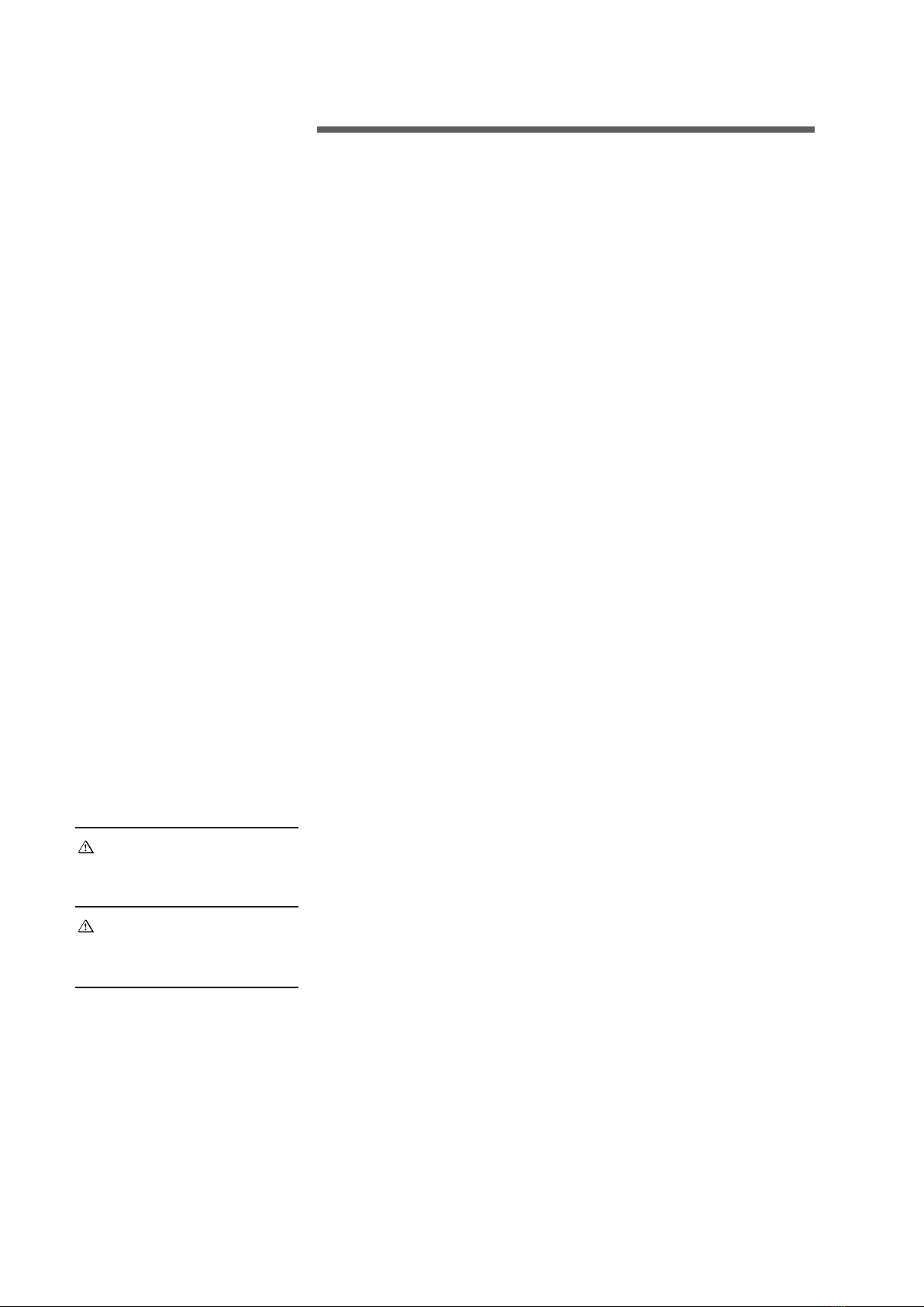
494—496 and reinstall the bolts to the cold water basin. Install the overflow
(fiberglass models only) as shown in Figure 1.
INSTALL DRAIN FITTING
WITH GASKET ON TOP
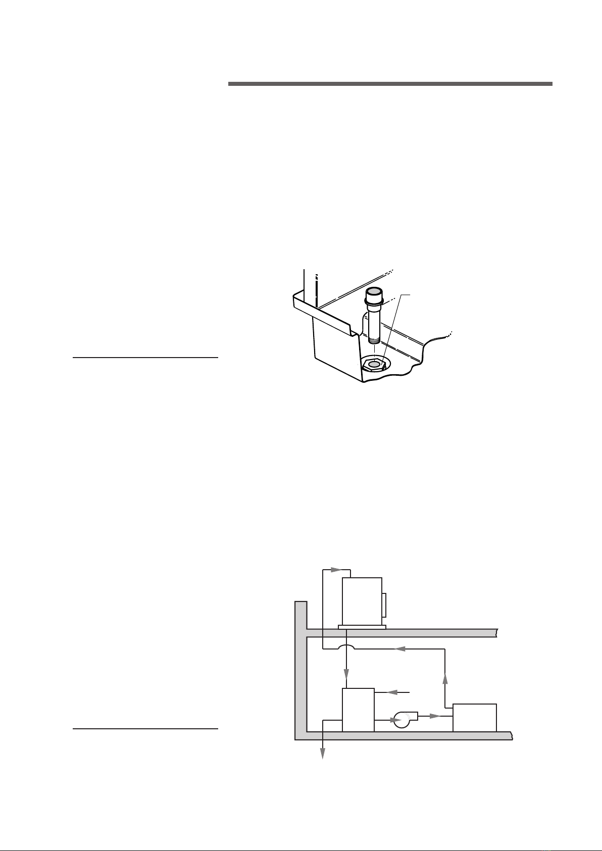
Cooling
Tower
with
Bottom
Outlet
Heat
Load
Indoor
Storage
Tank
Pump
Make-Up
Line
Inlet
Gravity Line
from Outlet
Overflow and
Drain to Sewer
Figure 2
Piping to Tower (Summer–Only Operation)
1. Use large enough piping to minimize friction loss.
2. Connect float valve to makeup water supply. Install the threaded valve
stem and float located in the loose parts package.
3. Install a valved blowdown line at some point in the system, preferably in
the hot water line near the top of the tower, so that water will flow through
the line whenever the pump is operating. (Blowdown is the continuous
removal of a small amount of water during operation to retard scale and
corrosion.)
Figure 1
➠

6
SUPPORT BRACKET
(WITH ADJUSTMENT SLOTS)
1/4" TAP SCREW
installation
Piping to Tower (Year–Round Operation)
1. If your tower must operate during freezing weather, it is recommended
that the tower be installed for gravity flow operation. See Figure 2.
2. Provide an indoor open type storage tank with a capacity that will contain
all water that will drain into the tank from the system during shutdown.
3. Connect tower outlet to storage tank. Bottom outlet option should be
used for gravity flow.
4. Install makeup water, bleed-off, overflow and drain lines on tank.
5. Insulate and heat water lines exposed to freezing temperatures.
Mechanical Equipment Installation
Aquatowers with factory-installed controls ship with the motor,
sheave, belt, and belt guard factory-installed. Remove shipping
stiffener plate and hardware at the adjustable end of the motor
support plate and proceed to Motor Electrical Connections.
Motor, Sheave, and V-Belt Installation
1. Check the motor nameplate to be sure its voltage, phase and frequency
ratings are the same as the power supply.
Note
Motor Frame Fastener
Size
56–143T–145T 5⁄16"
182T thru 215T 3⁄8"
Figure 3
➠
BELT GUARD FOR STEEL
AQUATOWER SHOWN
7
2. Make sure the fan is tightly secured to the bearing housing shaft and that
it rotates freely. Make sure the bearing housing is secured to its support.
3. Attach motor to motor base with four bolts, flat washers, lock washers
and nuts provided, see Figure 3. You may want to loosen the adjusting
bolts and raise the motor base so you can reach under the motor base
to tighten the motor hold-down bolts.
4. Apply a rust preventive coating to the motor shaft to prevent shaft corro-
sion and to ease sheave installation and removal.
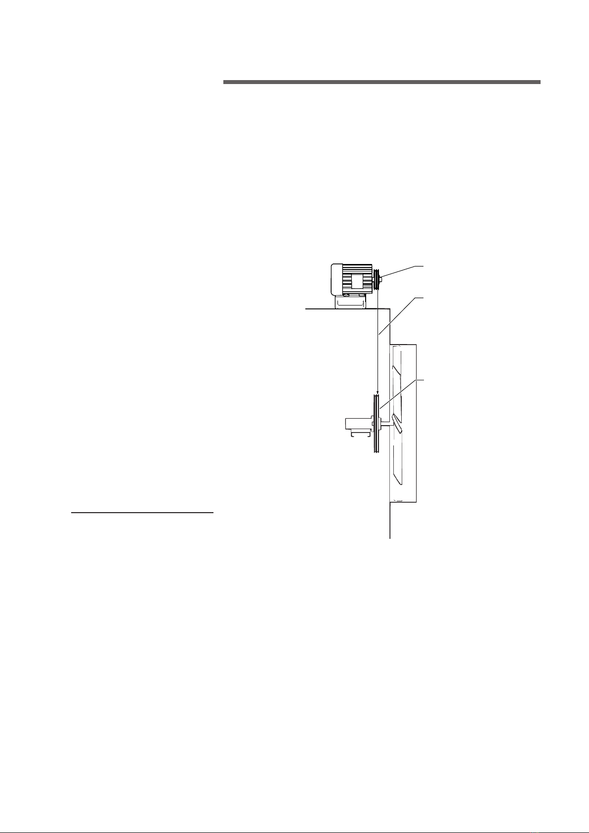
5. Install motor sheave and align it with fan sheave. Motor support brackets
are slotted to assist in alignment. See Figure 3. A plumb line will be helpful
in aligning sheaves. See Figure 4.
6. Remove the fan guard and fan cylinder splice plate (steel tower only) at
the top of the fan cylinder. Install the belt over the fan by passing the belt
over the fan and rotating the fan blades past the belt. Install the belt onto
the sheaves.
Figure 4
installation
PLUMB LINE
SHEAVES MUST BE PARALLEL TO
EACH OTHER AND IN THE SAME
PLANE OF OPERATION FAN SHEAVE
MOTOR SHEAVE
➠

8
installation
Figure 5
7. Use the adjusting bolts on the motor support to adjust belt tension. A
correctly tensioned belt does not slip when the fan is running—and the
“tight” side is straight between sheaves. The “slack” side will have a slight
bow. If possible, use a commercially available tension measuring device.
Avoid over-tensioning. Too much tension reduces bearing and belt life.
Check the tension on new belts after 8 to 12 hours of operation.
8. Install the belt guard as shown in Figure 3 for a steel tower or Figure 5
for a fiberglass tower.
9. Install fan cylinder splice plate (steel tower) and fan guard.
10. Check bearing housing oil cup level. Fill to the proper level with SAE 30
(ISO 100) weight oil.
3/8" x 1 1/2" BOLT
3/8" WASHERS
USE 3/8" WASHERS TO
SHIM AS REQUIRED
3/8" NEOPRENE WELL-NUT
BELT GUARD FOR FIBERGLASS
AQUATOWER SHOWN
9
Motor Electrical Connections
If Aquatower is equipped with Marley Control System, refer to Con-
trol System Manual for wiring instructions.
Internal space heaters may be present, depending upon the motor manufac-
turer. For space heater operation and wiring refer to Marley “Fan Motor”
User Manual Z0239042.
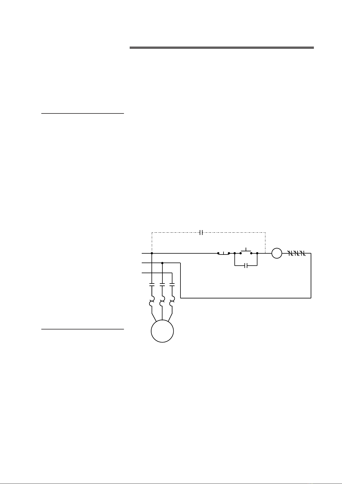
Connect motor to power supply in accordance with the National Electric
Code and local requirements. Failure to wire the motor correctly will void its
warranty. Overload protection for motors must be part of the control system.
Figure 6 shows one possible control scheme. Other various wiring diagrams
appear on pages 19 through 22.
Note
installation
L1
L2
L3
MMM
STOP START
M
M
OL
2-WIRE CONTROL (IF USED)
NOTE: L3 IS USED ON 3-PHASE MOTOR ONLY.
MOTOR
Figure 6

10
operation
Starting and Operating Instructions
Microorganisms including Legionella bacteria can exist in premise
plumbing including cooling towers. The development of an effective
water management plan (WMP) and implementation of maintenance
procedures are essential to prevent the presence, dissemination and
amplification of Legionella bacteria and other waterborne contami-
nants throughout premise plumbing. Before operating the cooling
tower, the water management plan and maintenance procedures
must be in place and regularly practiced.
1. Consult a knowledgeable water treatment professional to clean and treat
your new cooling tower prior to startup. Cooling towers must be cleaned
and disinfected regularly in accordance with local public health services
and recommendations.
2. Do NOT attempt any service unless the fan motor is locked out.
3. Clean all debris, such as leaves and dirt from the cooling tower fill and
basin.
4. Fill the circulating system with water. The cold water basin should be filled
with water until level is at the rim of the overflow.
The water conditions during the initial tower operation are crucial in pre-
venting premature corrosion of galvanized steel (white rust). For at least
the first eight weeks of operation, pH should be controlled between 6.5
and 8.0 with hardness and alkalinity levels between 100 and 300 mg/L
(expressed as CaCO3).
If tower is equipped with a standard side-suction connection, vent
any accumulated air from the top of the suction hood by removing
one or both tap screws provided at that location. Replace these tap
screws when venting is complete.
5. Start your pump(s). Observe system operation. Since the water system
external to the tower will have been filled only to the level in the cold water
basin, some “pump-down” of the basin water level will occur before water
completes the circuit and begins to fall from the fill. The initial pump-down
may not be enough to cause the float valve to open. However, you can
check its operation by pressing down on the operating lever. Adjust the
Warning
Note
Indice
Altri manuali Marley Congelatore


