
Master Image MI-HORIZON3D Manuale utente
Installation & Operation Manual | MI-HORIZON3D
55
MI-HORIZON3D
Digital 3D Cinema System
Installation & Operation Manual
Revision No. 1.0.0
Installation & Operation Manual | MI-HORIZON3D
© MASTERIMAGE 3D, Inc.
2
Revision History
Revision
Date
Release
Status
Author
Remarks
PD 0.1
24th February 2014
Preliminary
Document
RJG
PD 0.2
27th February 2014
Preliminary
Document
RJG
Changes to software utility
PD 0.3
6th March 2014
Preliminary
Document
RJG
Text Improvement
PD 0.4
12th May 2014
Preliminary
Document
RJG
Packaging additions
1.0.0
22nd May 2014
Initial Release
RJG
Copyright © 2005-2014 MASTERIMAGE 3D, INC
All Rights Reserved
MASTERIMAGE 3D, INC. Proprietary
All other trademarks and copyrights are the property of their respective owners.

Installation & Operation Manual | MI-HORIZON3D
© MASTERIMAGE 3D, Inc.
3
Locations
MASTERIMAGE 3D, INC
15260 Ventura Blvd Suite 1220
Sherman Oaks CA 91403
TEL: (323) 606-7800
FAX: (323) 301-7985
MASTERIMAGE 3D ASIA, LLC.
22F, BYC HIGHCITY B/D A,
371-17, Gasan-dong, Geumcheon-gu,
Seoul 153-803, South Korea
TEL.: +82-2-3438-1600
FAX: +82-2-3438-1698
MASTERIMAGE 3D EUROPE, PLC
Pinewood Studios
Pinewood Rd., Iver Heath
Buckinghamshire
England
SL0 0NH
TEL: +44 1753 785131
Fax: +44 1753 656050
URL: Uhttp://www.MASTERIMAGE3d.com
Email Contact: support@MASTERIMAGE3d.com

Installation & Operation Manual | MI-HORIZON3D
© MASTERIMAGE 3D, Inc.
4
Table of Contents
1. Introduction ............................................................................................................7
1.1. Welcome.......................................................................................................................7
1.2. Contacting Technical Support .......................................................................................7
2. Warnings and Cautions..........................................................................................8
2.1. Installation Consideration..............................................................................................8
2.2. Heat Damage................................................................................................................8
2.3. General Electrical Safety...............................................................................................8
2.4. General Handling..........................................................................................................8
3. System Overview ...................................................................................................9
3.1. The Next Wave in Digital 3D Projection.........................................................................9
4. Installation and Configuration...............................................................................10
4.1. Unpacking the MI-HORIZON3D..................................................................................10
4.2. Confirm Package Contents of MI-HORIZON3D...........................................................11
5. Detailed Component Overview.............................................................................12
5.1. Three-Way Beam Optical Head Assembly ..................................................................12
5.2. Actuator & Control Box................................................................................................13
5.3. Floor Stand .................................................................................................................14
5.4. Control Box –Front Panel & Connections......................Error! Bookmark not defined.
6. System Setup.......................................................................................................15
6.1. Initial System Assembly ..............................................................................................15
6.1.1. Attach Optical Head to Actuator.......................................................................155
6.1.2. Cable Connections.............................................................................................15
6.1.3. Initial Height Adjustment ....................................................................................15
6.1.4. Locking Feet......................................................................................................19
6.1.5. GPIO Cable .......................................................................................................19
6.2. Initial Test....................................................................................................................20
6.2.1. Auto Power On ..................................................................................................20
6.2.2. Actuator Operation –3D Position.......................................................................20
6.2.3. Actuator Operation –2D Position.......................................................................20
7. System Alignment ..............................................................................................211
7.1. Upper Beam Alignment...............................................................................................21
7.2. Lower Beam Alignment...............................................................................................22
7.3. 3D Phase Sync Polarity...............................................................................................23

Installation & Operation Manual | MI-HORIZON3D
© MASTERIMAGE 3D, Inc.
5
7.4.Actuator 3D Position ...................................................................................................23
8. Projector Configuration.......................................................................................244
8.1. Projector 3D File Configuration .................................................................................244
8.2. Series II Projectors....................................................................................................244
8.2.1. NEC Series II File Settings for External Server Playback.................................244
8.2.2. Christie Series II File Settings for External Server Playback ............................255
8.2.3. Barco Series II File Settings for External Server Playback ...............................255
8.2.4. IMB Configuration Settings ..............................................................................266
9. System Setup Using the Monitor Application .......................................................27
9.1. Initial Configuration .....................................................................................................27
9.2. Exceute the Monitor Application using a Web Browser ...............................................27
9.2.1. Changing the User Password ............................................................................28
9.3. System Operation via the Monitor Application.............................................................29
9.4. Position Movement via the Monitor Application ...........................................................30
9.4.1. 3D Position ........................................................................................................30
9.4.2. 2D Position ........................................................................................................31
9.5. Sync Polarity via the Monitor Application.....................................................................32
9.6. Setting 3D Position via the Monitor Application...........................................................33
9.7. Automation Source via the Monitor Application...........................................................34
9.8. Sync Pulse Automation Reference Frequency via the Monitor Application..................35
9.9. 2D Delay Time via the Monitor Application..................................................................36
9.10. Network Configuration via the Monitor Application ......................................................37
9.11. Sync Source via the Monitor Application .....................................................................38
9.12. Log File via the Monitor Application.............................................................................39
9.13. Factory Default via the Monitor Application .................................................................41
10. MI-HORIZON3D Troubleshooting ........................................................................42
10.1. Error Indication via LED Display..................................................................................42
11. Appendix A –Firmware Upgrade Process for MI-HORIZON3D...........................43
11.1. Prerequisites for Upgrading Firmware.........................................................................43
11.2. Firmware Upgrade Procedure.....................................................................................43
12. Appendix B –MI-HORIZON3D Automation........................................................477
12.1. Ethernet Automation ...................................................................................................49
12.1.1. Doremi Server....................................................................................................49
12.1.2. Qube Server ....................................................................................................555
12.1.3. GDC Server.....................................................................................................588
13. Appendix C –Installation Record.......................................................................644


Installation & Operation Manual | MI-HORIZON3D
© MASTERIMAGE 3D, Inc.
7
1. Introduction
1.1. Welcome
Congratulations on choosing the finest digital projection 3D system available.
The MASTERIMAGE MI-HORIZON3D delivers the clearest, brightest, full-color images
in a studio-approved single projection, patented three-way beam, liquid crystal, digital 3D
system.
Paired with MASTERIMAGE high quality 3D eyewear, the MI-HORIZON3D provides the
clearest and truest color 3D picture of any available liquid crystal 3D system.
This user manual provides all the information required for simple installations and the
operation of the MI-HORIZON3D, with any DLP cinema projector and digital cinema
server.
1.2. Contacting Technical Support
If you require technical support, our contact information is listed below:
MASTERIMAGE 3D, INC
Email: support@masterimage3d.com
Web Site: www.MasterImage3d.com
USA Tel: +1-323-606-7800
UK Tel: +44 1753 785131
Asia Tel: +82-2-3438-1600

Installation & Operation Manual | MI-HORIZON3D
© MASTERIMAGE 3D, Inc.
8
2. Warnings and Cautions
2.1. Installation Consideration
When planning installation of the MI-HORIZON3D, ensure that the image height entering
the system is less than 55mm.
The auditorium throw ratio should be greater than 1.5:1 for this version of the system.
2.2. Heat Damage
To avoid burning the polarizer film of the liquid crystal panel ensure a panel surface
temperature of <80˚F is maintained.
2.3. General Electrical Safety
Disconnect the power cord before servicing or opening the control box for any reason.
2.4. General Handling
Avoid touching any optical components with bare hands. Handle the optical head
assembly by the handles only.
Installation & Operation Manual | MI-HORIZON3D
© MASTERIMAGE 3D, Inc.
9
3. System Overview
3.1. The New Horizon of Digital 3D Projection
Key Features:
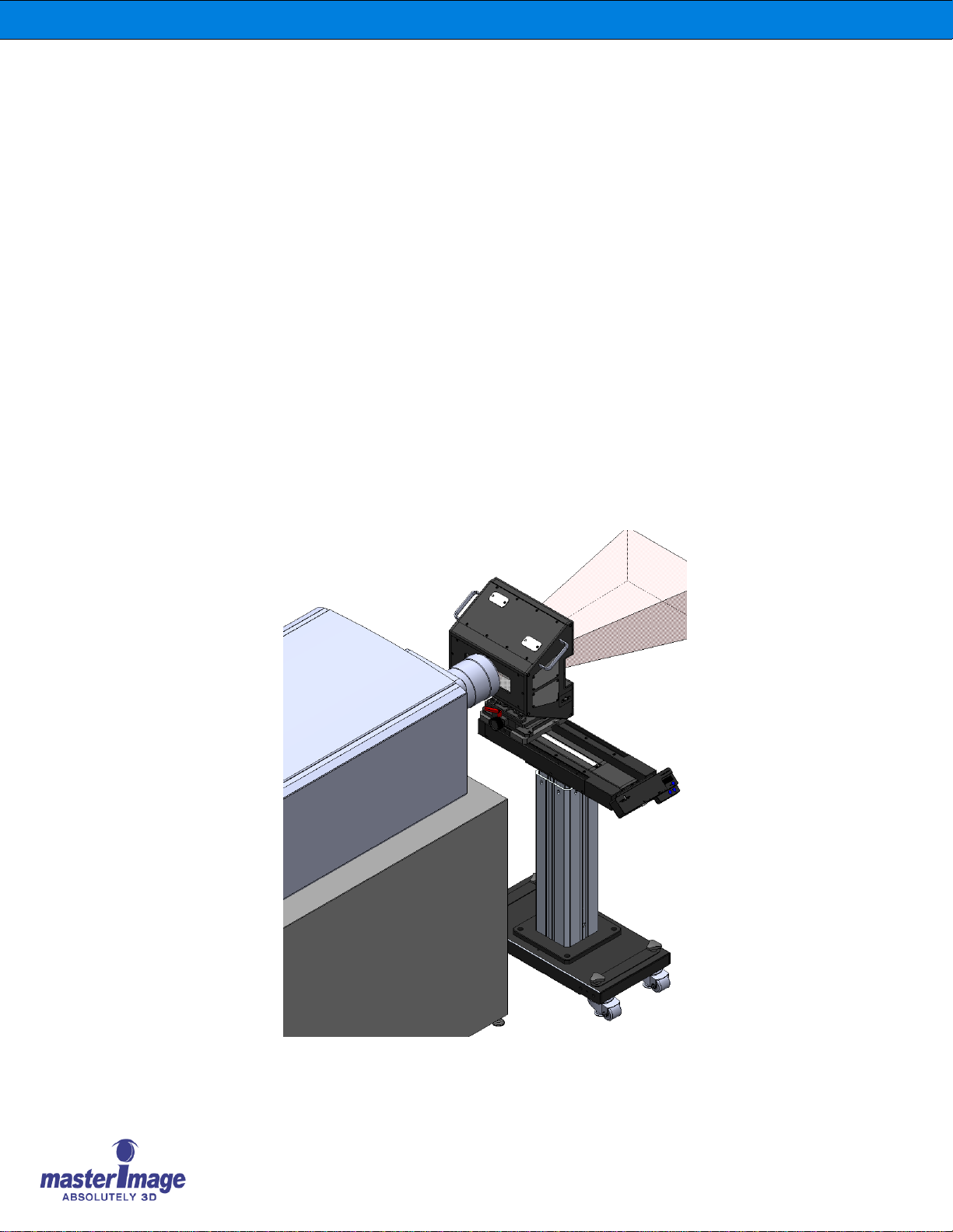
MI-HORIZON3D is a single-projection; three-way beam, liquid crystal based, easy-to-use,
high-quality Digital 3D Cinema System that enables 3D cinema presentation. The system can
be quickly installed in front of the lens of any DLP digital cinema projector.
MI-HORIZON3D’s patented construction three-way beam uses three specific Liquid Crystal
(LC) panels that are accurately bonded to ensure effective polarization of the left and right
images from the projector lens.
MI-HORIZON3D provides an accurate synchronization function for both current format 72Hz,
24fps, triple flash and future HFR 3D formats.
MI-HORIZON3D is perfectly matched to the high quality polarized 3D eyewear produced by
MASTERIMAGE 3D.
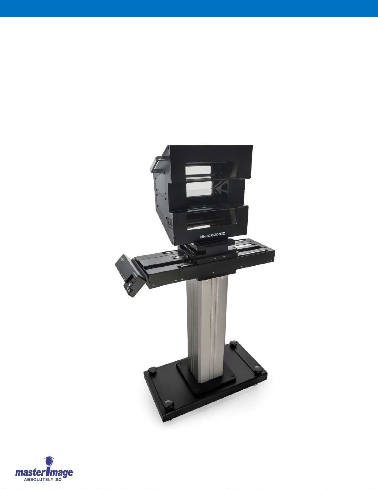
MI-HORIZON3D consists of the three-way beam optical head, actuator, control box,
connection cables, and floor stand.
Installation & Operation Manual | MI-HORIZON3D
© MASTERIMAGE 3D, Inc.
10
4. Installation and Configuration
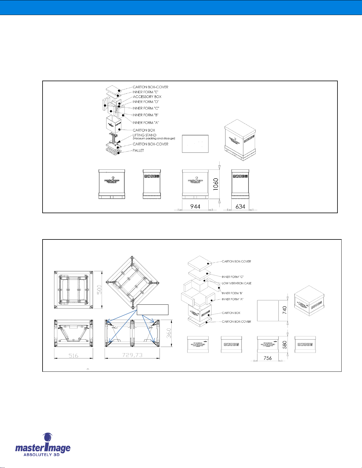
4.1. Unpacking the MI-HORIZON3D
Inspect the MI-HORIZON3D packaging box for any external damage. Report any damage to
shipper and to MasterImage 3D.
Top layer inside shipping carton
Head Assembly Outer Carton Box
Low Vibration Case for Head Assembly
Floor Stand Outer Carton contains Floor Stand, Actuator, Control Box and Accessories
SPRING
SSS
LOW VIBRATION CASE
(Vacuum Packaging & Silica
Gel)
Indice
Altri manuali Master Image Sistema Home Theater


