maturo NCD Manuale utente

Manual
for
Controller NCD
For the operation of Turntables TT,
Turn Device TD
and Antenna Masts

Index
1) General Instructions and Precautions Page 3
2) Technical Data of Controller NCD Page 4
3) Commissioning Page 6
4) Menu Guidance Page 7
4.1) Switch on Positioner Page 8
4.2) Referencing Page 10
4.3) Positioning Page 11
4.4) Actual and target position Page 12
4.5) Input of a Value Page 12
4.6) Settings Page 13
4.7) Setting of Tilt function and measurement Distance Page 13
4.8) Error Diagnostics Page 14
4.9) GPIB or LAN settings Page 15
4.10) Menu Page 15
4.11) GPIB or LAN Logger Page 16
4.12) Remote Address Page 16
4.13) PLC Update Page 17
5) Trouble Shooting Controller NCD Page 18
Appendix
- Warranty Statement Page 20
- Declaration of Conformity Page 21
- Remote commands Page 22
2

1) General Instructions and Precautions
Before this device is applied with power:
Ground it properly through the protective conductor of the power cable to a power source
provided with protective earth contact. Any interruption of the protective (grounding)
conductor, inside or outside the device, or disconnection of the protective earth terminal
could result in personal injury.
The electrical installation of this product must be accomplished by an individual who is
authorized to so do by the appropriate local authority. The installation must be in compliance
with local electrical safety codes.
Only qualified personnel are allowed to operate or service this equipment.
Before making service, contact maturo GmbH
Service or modifications of the device by yourself may void your warranty.
If you attempt to service the unit by yourself, disconnect all electrical power before starting.
There are voltages at many points in the components which could, if contacted, cause
personal injury. Only trained service personnel are allowed to perform adjustments and/or
service procedures upon this device. Capacitors inside this instrument may still be charged
even when instrument is disconnected from its power source.
Stay clear of moving components during the operation of the device.
Do not operate the device while somebody is close to moving parts.
The protection of the area of risk at site is part of the operator.
Read this manual completely before starting installation. This equipment must be installed
and operated only by qualified personnel.
Regularly inspect all equipment and conduct scheduled maintenance in accordance with
the factory recommendations provided. Only use replacement parts and fasteners ordered
directly from the factory.
Information presented enclosed is subject to change as product enhancements are made regularly.
Every effort has been made to ensure that the information in this manual is accurate. However, no
liability or guarantee is assumed for the up-to-dateness, correctness and completeness of the
information provided herein.
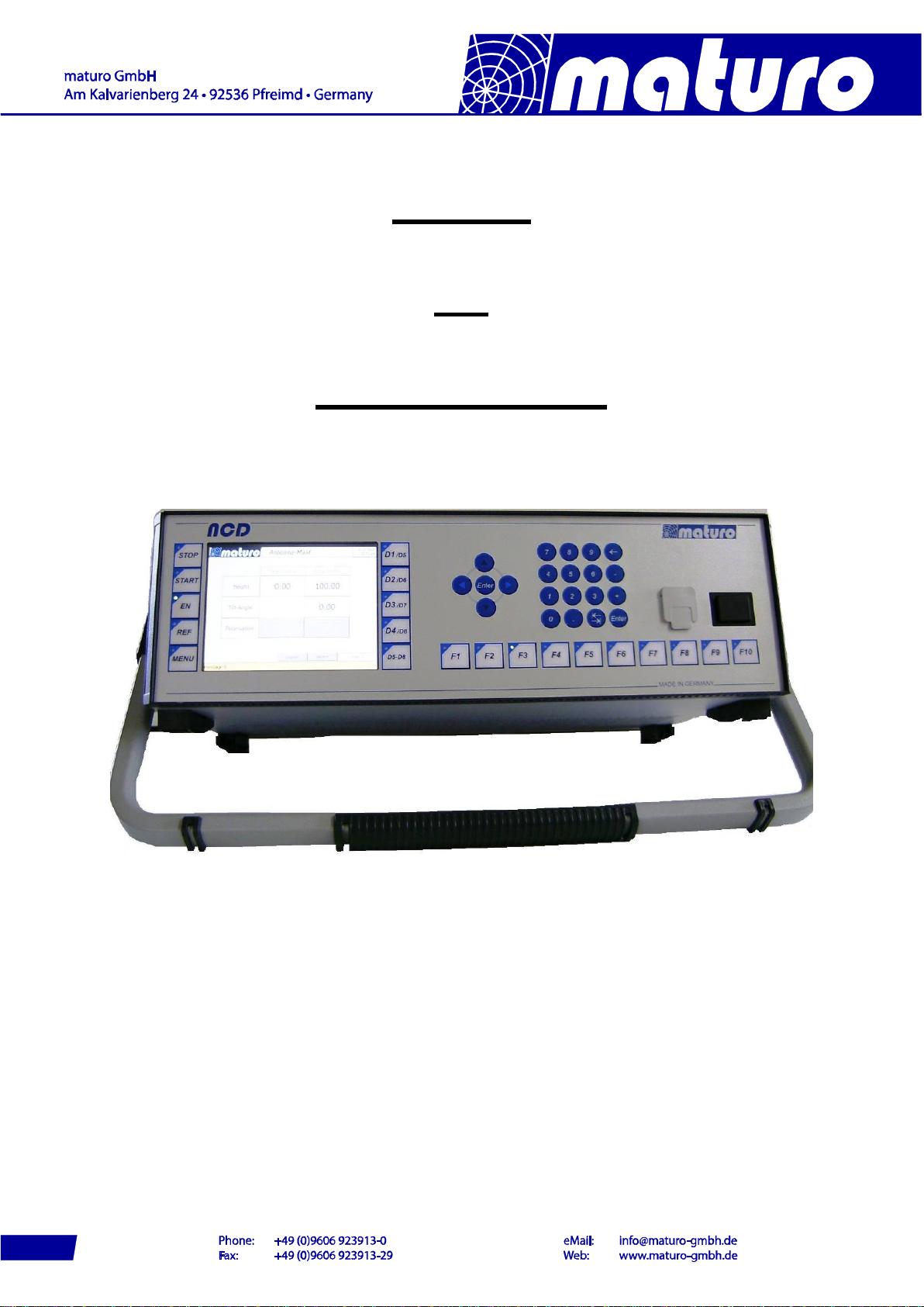
Pictures included are for illustration purposes only and do not represent all possible configurations.
3

2) Technical Data of Controller NCD
The Multiple Control Device NCD is suited for the operation of up to 8 devices with multiple
axis of motion. Those devices can be any combinations of antenna masts, turntables, cable
guide rails or any other positioning equipment.
This controller NCD permits the operation in manual, semi-automatic and remote control
mode via IEEE 488.2 (GPIB bus), or optionally other interfaces, of multiple devices
simultaneously.
Figure: NCD with option “tip-up handle”
Technical Data
Data interfaces IEEE 488.2 (GPIB-Bus) and Ethernet
Transmission Fibre optic cable 1G50/125 (up to 2000 m distance)
Transfer rate 100 Mbit/s (fast Ethernet)
Display 5.7“ TFT Touch screen-Display
Voltage 100-240 VAC, 47-63 Hz, single phase
Current consumption max. 70W
Fuse 2x T 1.6A
Size (W X D) 19” Rack mount and table unit (427 x 300 mm)
Height 3 HE (133 mm)
Temperature range 5°C - 40°C
Total weight approx. 8 kg
Accessories 1.5 m power supply cable, Service manual
4

Brief description of NCD
The multiple control device NCD works with KeySight (former Agilent), R&S, Teseq and other
software. The IEEE 488 (GPIB) is available as a standard interface device. Other interfaces
available upon request.
Highlights:
-User-friendly, time-saving function keys optionally available
The function keys F1 to F10 allows the implementation of individual, customer-
specific sequence programs for user-friendly, times-saving handling and operation.
The individual programs can be stored and accessed by one function key.
-Error analysis based on error codes
Diagnosis via USB interface possible
Optional analysis via internet and Ethernet interface possible
-USB interface
Updates easily implemented by USB stick
Possibility to plug in a computer mouse and keyboard
-Easy operation with touch panel
Fast and reliable operability based on touch panel technology
Layout of touch screen display can easily be adjusted according to customers’
request
-Position keys
With the position keys JOG+/JOG- the Positioners can easily be moved in manual
mode.
-Real-time capable
Each program cycle will finished in the default time frame be no matter how many
devices are controlled at the same time. Due to this feature no overflow of commands
can happen when using fast remote computers.
-Handheld control unit
Easy implementation of standard or customer-specific handheld control units possible
-Precise Display Accuracy
The display resolution is highly precise with position readout increments of 1 mm
respectively 0.1 degree.
Higher resolutions possible upon request.
-Many additional options possible
Emergency stop buttons, handheld control units (HCU), luminaire, analogue outputs
and much more additional features upon request
5

3) Commissioning Controller NCD
Bus Connection
The connection between the Controller NCD and the Positioner is performed by the included
fibre optic cable.
Take care that the colours of cables match with the stickers at the backside of the controller
and the drive units.
All Positioners will be activated automatically. If an additional device is connected, there is no
need of a restart.
Power Supply
The power supply of all devices must be 110-240 VAC / 47-63Hz.
Switch On
Switch on black power switch of the Positioners.
Switch on black power switches at front and back of the controller.
Attention: The fibre optic cables of NCD are highly sensitive, ensure that it is not
bent too much or gets damaged any otherwise!
If cables or ports are not in use, the included dust protection covers
must be used!
Even a minor, hardly visible dirtying of cable ends or feed-throughs
(FSMA) harms the connection, up to complete communication
malfunction!
Therefore please have a look at Chapter 5) Troubleshooting.
6

4) Menu Guidance
Panel
The picture below shows the control panel
Switch On
The following picture appears after boot routine.
(Note: The picture above may not the original picture for your controller)
There is no need to connect your D1 Device to the first port.
Each device can be connected to any free port of NCD.
Stop-Key
Start-Key
Enable-Key
Reference-Key
Menu-Key
Device selection
Switch Device 1-5 to 5-8
Keyboard
USB-Ports
Power switch
F-Keys
7

4.1 Switch on Positioner
- By pressing “EN“ key all Positioner will
be activated and the LED light up green
permanently.
- By pressing e.g. “D1/D5”, each single
device can be activated or deactivated.
Whereas, at deactivating the button must be
pressed for a longer period.
- To operate the devices D5 to D8, the
button “D5-D8” must be pressed first.
LED D5-D8 out: Device D1 to D4
LED D5-D8 on: Device D5 to D8
- Press the relevant button for switching to
the other Positioners.
- In general, the devices are active where
the LED light is on.
8

Note: The following brief descriptions are examples, but the controlling of most
positioners is similar. Possibly your Device doesn’t have all described functions.
By selecting a turntable the picture below appears. There is no need to reference the
turntable. The displayed value of “Actual Angle” is indicated by an absolute encoder which is
saving the last position, even after power off.
By pressing “To Settings” the adjustment possibilities for the device are shown.
By pressing key for Antenna Mast the picture below appears and the antenna mast is
activated. Masts must be referenced before positioning is enabled. By pressing “To Settings”
the adjustment possibilities for the device are shown.
Note: Yellow characters indicate the actual values.
At the bars which are indicated in white characters, input options are possible
9

4.2 Referencing
Before moving the antenna masts, they must be referenced.
Press “REF”-button after selecting a device in the user interface.
During the referencing, the LED of the “REF”-Button is blinking, after completion it lights
permanently. This process must be done with every Mast device and after every restart of
the NCD or of the device.
It is recommended to move masts to a low position before power off; otherwise the
referencing can take a long time.
If you have a TAM or BAM device, the buttons “Tilt Up” and “Tilt Down” can be used to adjust
the carriage considering to the bubble level. The angle is saved as 0⁰by pressing “Tilt Save”
and the referencing of high starts automatically.
Other masts as AM or CAM will reference fully automatic by pressing the “REF”-button.
Referencing of TAM (or BAM)
If you have a TAM or BAM device, the buttons “Tilt Up” and “Tilt Down” can be used to adjust
the carriage considering to the bubble level.
The angle is saved as 0⁰by pressing “Tilt Save” and the referencing of high starts
automatically.
These three buttons are also at the side of the drive box of TAM or BAM.
Other masts as AM, CAM or DAM will reference fully automatic by pressing the “REF”-button.
10
Indice


