
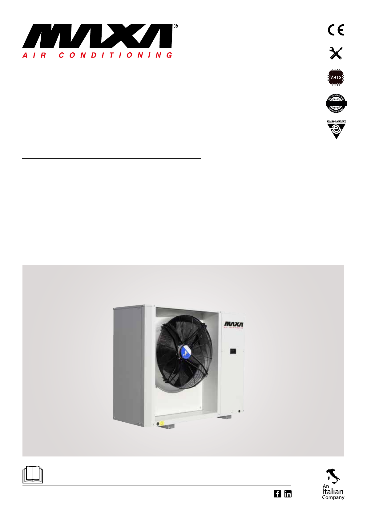
MAXA i-32V5H MIDI 0121 Manuale di servizio
www.maxa.it
R32
i-32V5H MIDI 0121
i-32V5H MIDI 0126
i-32V5H MIDI 0128
i-32V5H MIDI 0132
Chiller and Inverter Air/Water heat pumps with axial fan
Model

i-32V5H MIDI Chiller and Inverter Air/Water heat pumps with axial fan
2
00 01-2021
Rev Date Compiled Approved Note
Code Serie
BTE01040101001.00_i-32V5 Midi_EN Chiller and Inverter Air/Water heat pumps with axial fan

i-32V5H MIDI Chiller and Inverter Air/Water heat pumps with axial fan
3
Contents
1.DESCRIPTION OF UNIT AND TECHNICAL SPECIFICATIONS ................................................ 5
1.1 FRAMEWORK............................................................................................................... 5
1.2 COMPRESSORS ............................................................................................................ 5
1.3 AIR SIDE HEAT EXCHANGER ......................................................................................... 5
1.4 UTILITY SIDE HEAT EXCHANGER .................................................................................. 5
1.5 FAN .............................................................................................................................. 5
1.6 COOLING CIRCUIT........................................................................................................ 5
1.7 ELECTRICAL AND CONTROL PANEL .............................................................................. 6
1.8 CONTROL AND PROTECTION DEVICES......................................................................... 7
1.9 HYDRAULIC CYRCUIT ................................................................................................... 7
2. DESCRIPTION OF VERSIONS AND ACCESSORIES ................................................................ 7
2.1 VERSIONS .................................................................................................................... 7
2.2 LIST OF ACCESSORIES .................................................................................................. 8
2.3 DESCRIPTION OF ACCESSORIES ................................................................................... 9
2.3.1 Factory-ed accessories......................................................................................... 9
2.3.2 Accessories supplied separately............................................................................... 9
3.INSTALLATION.................................................................................................................. 11
3.1 UNIT DIMENSIONS, HYDRAULIC CONNECTIONS, WEIGHTS AND CENTRE OF GRAVITY
POSITION............................................................................................................................ 11
3.1.1 Net dimensions and with packaging ...................................................................... 11
3.1.2 Detail of connecons and locaon ........................................................................ 12
3.1.3 Weights .................................................................................................................. 12
3.1.4 Locaon of the centre of gravity and vibraons dampers......................................12
3.2 TECHNICAL SERVICE AREAS ....................................................................................... 13
3.3 HYDRAULIC CIRCUIT .................................................................................................. 15
3.3.1 System water specicaons ................................................................................... 16
3.3.2 Typical hydraulic scheme ....................................................................................... 16
3.3.3 Hydraulic diagram inside the unit .......................................................................... 17
3.3.4 Minimum water content and hydraulic circuit volumes......................................... 18
3.3.5 Condensate drainage system.................................................................................. 18
3.3.6 System charging/discharging.................................................................................. 19
3.3.7 Air vent valve.......................................................................................................... 19
4.TECHNICAL DATA ............................................................................................................. 20
4.1 HEAT PUMP DATA SHEET ........................................................................................... 20
4.2 DATA SHEET UNIT WITH DESUPERHEATER ................................................................ 21
4.3 UNIT AND AUXILIARY ELECTRICAL DATA.................................................................... 22
5. CORRECTIVE FACTORS ..................................................................................................... 22
5.1 CORRECTION FACTORS FOR USE OF WATER-GLYCOLE MIXTURE...............................22
5.2 SCALING CORRECTION FACTOR ................................................................................. 22
5.3 CaLIBRATIONS AND PROTECTIONS CONTROL............................................................ 22
5.4 CORRECTION FACTORS DEPENDING ON ALTITUDE ................................................... 23
6. HYDRONIC GROUP DATA DATI DEL GRUPPO IDRONICO .................................................. 24
6.1 USEFUL HEAD ............................................................................................................ 24
6.2 PRESSURE DROP Y-FILTER ACCESSORIES 3-WAY VALVE ............................................. 24

i-32V5H MIDI Chiller and Inverter Air/Water heat pumps with axial fan
4
6.3 CIRCULATOR/PUMP CURVES ..................................................................................... 25
7. SOUND EMISSIONS.......................................................................................................... 26
7.1 POWER AND SOUND PRESSURE STANDARD ............................................................. 26
8. OPERATING LIMITS .......................................................................................................... 27
8.1 WATER FLOW RATE AT THE EVAPORATOR ................................................................. 27
8.2 CHILLER WATER PRODUCTION (SUMMER OPERATION) ............................................27
8.3 HOT WATER PRODUCTION (WINTER OPERATION) .................................................... 27
8.4 AMBIENT AIR TEMPERATURE AND SUMMARY TABLE ............................................... 27
9. PERFORMANCE TABLES ................................................................................................... 29
9.1 HEATING .................................................................................................................... 29
9.2 COOLING.................................................................................................................... 30
9.3 SANITARY ................................................................................................................... 31
9.4 DATA FOR ENERGY CERTIFICATION OF BUILDINGS ACCORDING TO UNI/TS 11300-4 FOR
HEAT PUMPS....................................................................................................................... 32
9.4.1 Model i-32V5H MIDI 0121...................................................................................... 32
9.4.2 Model i-32V5H MIDI 0126...................................................................................... 33
9.4.3 Model i-32V5H MIDI 0128...................................................................................... 33
9.4.4 Model i-32V5H MIDI 0132...................................................................................... 34
9.5 EER VALUES FOR CALCULATING THE ENERGY PERFORMANCE OF BUILDINGS ACCORD-
ING TO UNI/TS 11300-3...................................................................................................... 36
9.5.1 Model i-32V5H MIDI 0121...................................................................................... 36
9.5.2 Model i-32V5H MIDI 0126...................................................................................... 36
9.5.3 Model i-32V5H MIDI 0128...................................................................................... 37
9.5.4 Model i-32V5H MIDI 0132...................................................................................... 37
10.REFRIGERANT SAFETY SHEET......................................................................................... 38

i-32V5H MIDI Chiller and Inverter Air/Water heat pumps with axial fan
5
1. DESCRIPTION OF UNIT AND TECHNICAL SPECIFICATIONS
The heat pumps in this series were designed for residenal and commercial applicaons. They are extremely versale and are designed for
heat pump operaon with hot water producon for space heang and sanitary use at a temperature of 60°C. The use of the brushless inverter
compressor technology, combined with the electronic expansion valve, the circulator and the variable speed fan, opmise the consumpon and
operang eciency of the cooling components.
FRAMEWORK
Structure suitable for outdoor installaon consisng of thick proles made of hot galvanised sheet steel and painted with polyester powder, co-
lour RAL 7035 textured, resistant to atmospheric agents. The removable panels allow maintenance inside the refrigeraon and hydraulic circuits.
COMPRESSORS
Twin rotary hermec inverter controlled DC compressors, specically designed to operate with R32, equipped with thermal protecon and
mounted on rubber vibraon dampers.
This component is installed in a compartment separate from the air ow to reduce noise and is equipped with a crankcase heater that prevents
the diluon of the oil by the refrigerant, ensuring correct lubricaon and reducing wear on moving parts.
The compressors can be inspected by removing the side and front panels of the unit, allowing maintenance even when the unit is running.
AIR SIDE HEAT EXCHANGER
The air exchangers are made of copper tubes and aluminium ns.The pipes are mechanically expanded in the alluminium ns to increase the
heat exchange factor.The geometry of these exchangers allows a low value of pressure losses on the air side and therefore the possibility of using
fans with a low number of revoluons (with a consequent reducon in machine noise).
On request, the coils can have surface treatments to allow greater resistance to corrosion or be made enrely of copper with a brass structure.
UTILITY SIDE HEAT EXCHANGER
Brazed plate heat exchanger made of AISI 304 stainless steel, covered with black exible closed-cell elastomeric foam; thickness 9 mm, thermal
conducvity (λ)≤0.036 W/mK (at air +20°C). A ow switch installed on the water side ensures the presence of water ow and, together with the
protecon probe, prevents the formaon of ice inside.
The exchanger can be equipped with an electric anfreeze heater (oponal accessory KA1)
FAN
The fans are axial type with airfoil blades They are stacally and dynamically balanced and supplied complete with protecon grille and air inlet
and outlet with double ared prole, specially shaped to increase eciency and reduce noise. The electric motor used is driven in modulaon
with brushless EC motor, directly coupled, and equipped with integrated thermal protecon. The motor has an IP 54 protecon rang according
to CEI EN 60529.
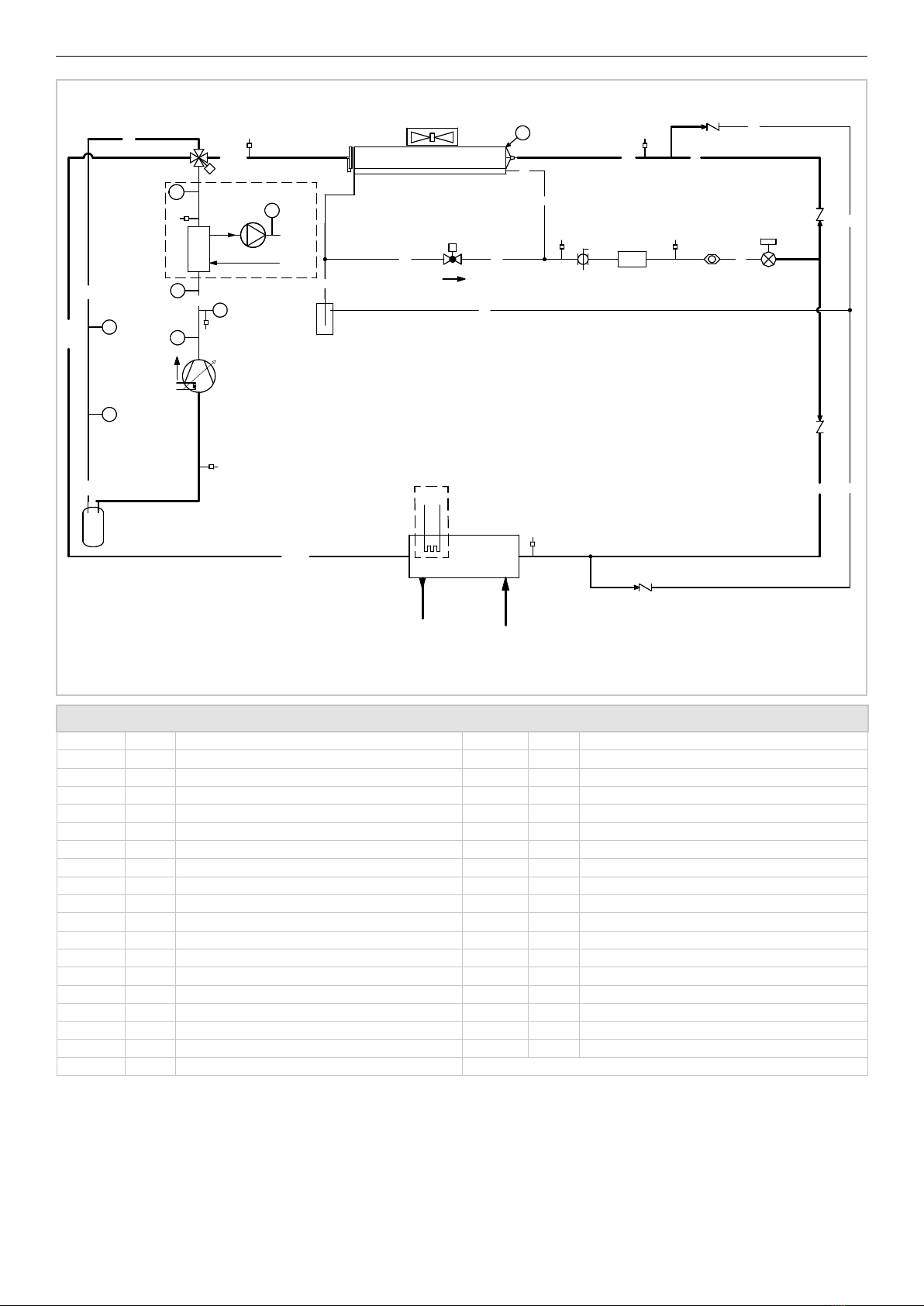
COOLING CIRCUIT
The cooling circuit is made of copper piping, brazed and assembled in the factory in accordance with EN 13134.The components present are:
• Filter drier with 100% molecular sieve cartridge;
• Shut-o valve on the liquid line;
• Liquid ow and moisture indicator;
• Electronic expansive valve;
• Charge connecons;
• High-pressure safety pressure switches;
• High and low pressure transducers;
• Reverse cycle valve;
• Receiver and liquid separator.
The sucon line is thermally insulated with exible, closed-cell elastomeric foam.
Each unit is pressure tested to check for leaks and is supplied complete with a refrigerant charge opmised for operaon.
i-32V5H MIDI Chiller and Inverter Air/Water heat pumps with axial fan
6
RD/RS
RD
PSH1
RS
SL1
RS/RD
PEH
TC1
SG1
RL
RL
RL
TE
SD1
SV
PED
TR1
SV
F1
SBSV 1
SB
SV
RL
SV
SV
RL
RS/RD
RS
SB
RL
RS
RL
CV1
RL
RL
CV4
AF1
RL
RL
LR1
CO/EV1
INVC1
HC1
P-DS1
TE
PD1
DS1
SV
BV1
TE
DS 1
DHW-OUT
DHW-IN
TE
EXT1
SV
SV
CV2
CV3
W-IN
W-OUT
KA1
EV1
TE
DT1
EEV1
LEGEND
INVC 1 1
1 1
1
1 1
1
1 1
HC 1 1
1 1
1
1
1
1
1
1 1
1
1
CV W-IN
1
---
ELECTRICAL AND CONTROL PANEL
Completely manufactured and wired in accordance with IEC 60335-2-40.
The power secon includes:
• Isolaon transformer for control power supply;
• Thermal protecon fuses for compressor driver and EC fan;
• Automac switch for compressor protecon (oponal);
• Driver for modulang compressor control;

i-32V5H MIDI Chiller and Inverter Air/Water heat pumps with axial fan
7
• Phase sequence control relays;
• Phase sequence control relay with minimum/maximum voltage seng (oponal);
• Thermostacally controlled venlaon inside the electrical panel;
• GI module - system management. (oponal or for versions that require it).
The control secon includes:
• Interface terminal with alphanumeric display;
• Display funcon for set values, analogue inputs, fault codes, alarm history and parameter index;
• Key on/o and alarm reset;
• Key combinaons to force defrost and force pump to maximum speed;
• Management of unit start-up from local or remote;
• ModBus connecvity (oponal);
• BMS connecvity via converter
• BMS connecvity (ModBus/Bacnet/Knx/Lonworks) - oponal.
• BMS connecvity (ModBus/Bacnet/Knx/Lonworks) - oponal.
CONTROL AND PROTECTION DEVICES
All units are equipped as standard with the following control and protecon devices: inlet water temperature probe installed on the water return
pipe from the system, outlet water temperature probe that also funcons as an an-freeze probe installed on the water supply pipe to the sys-
tem, high pressure transducer, low pressure transducer, compressor sucon and discharge temperature probes, compressor thermal protecon,
fan thermal protecon, ow switch on the water side to protect the evaporator, high pressure switch.
HYDRAULIC CYRCUIT
The units in the series are supplied with a built-in hydraulic circuit that includes: high-eciency brushless motor modulang circulator (EEI≤0.23),
suitable for the use of chilled water and directly controlled by the on-board control, plate heat exchanger, protecon ow switch, safety valve
(6 bar) to be connected to a collecon system and manual air vent valve.
2. DESCRIPTION OF VERSIONS AND ACCESSORIES
VERSIONS
The available versions are:
i-32V5H Midi - heat pump standard version
i-32V5H-DS Midi - heat pump with superheater
The unit with desuperheater includes the addion of a brazed plate type heat exchanger made of AISI 316 stainless steel, factory insulated using
closed cell material. This version allows to recover about 20% of the condensing heat otherwise lost and to use it to feed the aer-heang water
coils of an AHU or for a hot water ywheel or for any other process use.
i-32V5H-BT Midi - chiller BT version (for low water temperature)
The BT version of the unit allows the operang range of the unit to be extended by cooling the water supplied to the user down to -8°C. In this
case, a mixture of water and glycol is used.
i-32V5H MIDI Chiller and Inverter Air/Water heat pumps with axial fan
8
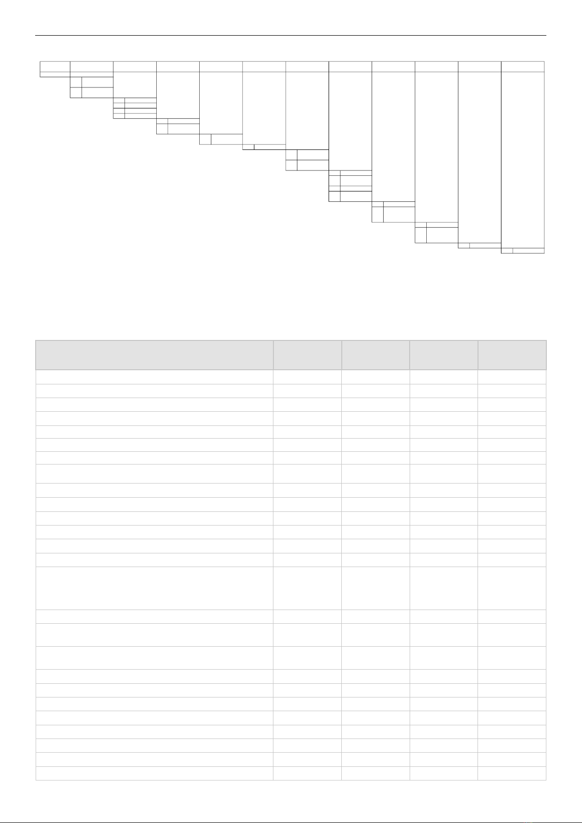
Order code
0110820#
57 Reversible heat
pump
55 BT version on
heat pump
24
0121
25
0126
26
0128
27
0132
0
2 pipes
3Desuperheater
circuit
0 Without injection
0
No silencing
0
Without antifreeze
kit
1 With antifreeze kit
0
Without GI/GI2*
1With GI/GI2 plant
operator
2
Modbus (CM)*
3 Modbus (CM) +GI
0
Standard
2
Thermomagnetic
circuit breakers
(IM)
0
No one
8
Battery with
treatment
Silverline (TR2)
0
No one
01
Standard
Code
EL3
TR
AC1
Unit version Thermal capacity Water pipe configuration Antifreeze kit accessory
System management
module
RV
CT1
TA
KA
GI
MC
Injection (LT) Silencing
IV
SIL
Electrical variants
Accessory - battery
treatment Accessory 1
* Not valid if TA=3
LIST OF ACCESSORIES
Available accessories are indicated below:
Accessory Standard
Supplied loose/
delivery
x x
x x
x x
x x
x x
x x
x x
tank x x
x x
x x
x x
x x
x x
x x
x x
x x
x x
x x
x x
x x
x x
x x
x x
x x
x x
x x

i-32V5H MIDI Chiller and Inverter Air/Water heat pumps with axial fan
9
DESCRIPTION OF ACCESSORIES
nned pack heat exchanger with copper tubes and aluminium ns, treated with a special polyurethane-based paint for corrosion protecon.
The treatment makes the coil exible to resist thermal expansion and contracon, mechanically resistant, UV protected and dirt repellent. The
treatment guarantees protecon of the baeries in praccally all environmental condions: from marine to rural environments, from industrial
to urban areas.
For specic cleaning instrucons for baeries treated in this way, please refer to the chapter in the user-installer manual entled "Cleaning of
nned baeries treated with the corrosion protecon method".
The treatment resists 6000 h according to ASTM B117.
Electronic expansion valve
expansion valve, designed for the control and connuous regulaon of the amount of refrigerant fed into the evaporator. Changes in thermal
load may be followed quickly, so as to achieve opmised consumpon.
Electronic circulator
standard of the unit, electronically controlled and high eency.
Water-side safety valve
Valve installed on the hydraulic circuit to control overpressure ola installata sul circuito idraulico per controllare le sovrapressioni – taratura 6 bar
device that controls and signals the circulaon of water in the plate heat exchanger. This component is of fundamental importance because it
shuts down the unit and makes it safe by prevenng the formaon of ice.
metal mesh to prevent the intrusion of foreign bodies inside the coil and to protect the coil from accidental contact with things or people.
electric resistance located on the front face of the plate heat exchanger, which is acvated when the temperature of the water inside the ex-
changer falls below +4°C. For BT units this value must be set according to the percentage of glycol in the system and the freezing point of the
mixture. An electrical resistance is also placed on the base of the unit and is acvated when the outside temperature falls below the set level.
contact on the terminal board that allows the unit to be switched on and o.
Dynamic set point
the regulator allows the set-point to be modied by adding a value according to the temperature of the external air probe.
allows the management of the following funcons:
• Compressor ON/OFF signalling
• General alarm signalling/Machine block signalling
signals the presence of all three phases in the correct sequence.
signals if all three phases are present in the correct sequence and if all three phase-to-phase voltages are within the set limits. The maximum and
minimum voltage thresholds can be set separately.
Overcurrent circuit breaker applied upstream of electrical components, protects components from failures caused by current peaks.
Accessories supplied separately
Y-Filter
contains a stainless steel mesh sieve (500 μm ltraon) that collects solids in the water. Filtraon prevents clogging and/or
damage to devices installed downstream of the lter.
temperature probe to be placed inside a thermal ywheel for the instantaneous producon of domesc hot water. The DHW storage remote
probe thermoregulates the heat pump both during compressor start-up and shutdown.
The probe cannot be connected in the case of DS version
system temperature probe to be posioned inside an external tank. The remote system probe thermoregulates the heat pump only during the
compressor start-up phase; shutdown is managed by the probe on the unit's delivery side.
i-32V5H MIDI Chiller and Inverter Air/Water heat pumps with axial fan
10
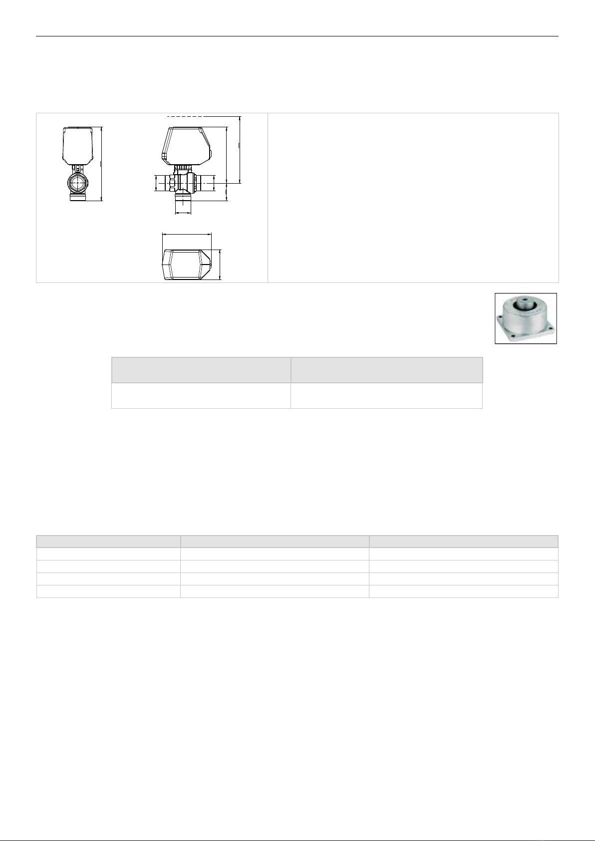
Motorised three-way sphere valve DN (1”1/4) Kvs 20,8, complete with servocontrol.
11/4"G
11/4"G
11/4"G
64
167
118
47
104
130
MIN.
Maximum operang pressure : 10 bar
Maximum dierenal pressure : Δp = 6 bar
Fluid working temperature : 0 ÷ + 100 °C
Usable uid: Water or compable liquids with TEFLON and EPDM seals
Pressure drop : almost zero
are designed to prevent the transmission of vibraons to the structure; they are to be mounted under the unit in special
holes.
The opmum recommended load capacies, depending on the size of the machine, are given below
Model i-32V5H Midi
63
accessory allowing connecon of the unit to external controllers via serial cable with RS-485 electrical standard and ModBus RTU protocol.
Fan silent mode
Digital input that can be acvated by an external contact to reduce the sound power level by acng on the venlaon. The mode is parcularly
suitable during night operaon. Below are the decreases in capacity and sound power level when the "fan silent mode" funcon is acve.
The reducon refers to the test condion (3) of the technical data tables; the value is determined on the basis of measurements carried out in
accordance with UNI EN ISO 9614-2, in compliance with the requirements of Eurovent cercaon.
Model i-32V5H Midi
0121 -1
0126 -1
0128 -1
0132 -1
Serial converter USB RS485 (ISK)
interface device capable of reading and wring control registers via the RS485 standard and converng it to a USB port that can be connected
to any supervisory system.
device that enables conversion between Modbus RTU and BACnet/ Lonworks, allowing the unit control to be congured as a normal device in
the BACnet / Lonworks network.
device that enables conversion between Modbus RTU and BACnet/ Konnex, allowing the unit control to be congured as a normal device in the
BACnet/ Konnex network.
7-touch/HUB (Cloud/App)
is a compact system consisng of an ultra-thin touch panel, including a temperature control unit and gateway for remote control from a PC (
through the " my.maxa.it" portal) or smartphone (through the app that can be downloaded from the "My Maxa" online store). It allows winter
and summer climate control.
Questo manuale è adatto per i seguenti modelli
3
Indice
Altri manuali MAXA Refrigeratore

MAXA
MAXA i-32V5C MIDI 0121 Manuale utente

MAXA
MAXA A68 Manuale utente

MAXA
MAXA HWA-ZA Manuale utente

MAXA
MAXA HWA-A 06195-121031 Series Guida

MAXA
MAXA i-32V504 Manuale utente

MAXA
MAXA i-32V5C MIDI 0121 Manuale utente

MAXA
MAXA N-i-HP 0125 Manuale per l'uso e la cura

MAXA
MAXA HWA1-A 0140 Manuale utente

MAXA
MAXA HMV-A Series Manuale utente

MAXA
MAXA i-32V504 Manuale utente


