MAXIMATOR GX35 Manuale utente
Operating instructions
MAXIMATOR Pump
Types GX35, GX60, GX100
MAXIMATORGmbH
D-37449 Zorge / Südharz
Phone: +49-(0)5586/803-0
Fax: +49-(0)5586/80340

Attention!
These operating and maintenance instructions for a MAXIMATOR product
have been prepared for operators.
The instructions will defeat their purpose when they are not passed on to
system operators and are not studied and used.
The documentation prepared by us reflects the current manufacturing status.
We reserve minor design changes.
If an operator fails to understand any of the instructions we invite them to call
us and quote the relevant serial No. indicated in the cover sheet of this
documentation and in the machine plate.
MAXIMATORGmbH
D-37449 Zorge / Südharz
Tel.: +39-(0)5586/803-0
Fax: +39-(0)5586/80340

Important!
We as the manufacturer of this product have taken account of the fundamental health and
safety requirements during the design and fabrication of the entire product.
The owner of the system has to see to it that the operating personnel will continue to
adhere to the applicable regulations during any required work.
Specific requirements are laid in the following standards:
- EC Machine Directive in the version 98/37/EG
- EC Pressure Equipment Directive 97/23/EC
- EN 292-1 Machinery safety - Basic concepts, general principles for design.
- Part 1: Basic terminology, methodology.
- EN 292-2 Machinery safety - Basic concepts, general principles for design.
Part 2: Technical principles and specifications.
- EN 294 Machinery safety, Safety distances to prevent danger zones from being
reached by the upper limbs.

Table of contents
1. Operating instructions for MAXIMATOR pumps
1.1 Technology
1.2 Technical data
1.4 Wearing part kits
1.5 Performance curve GX35
1.6 Performance curve GX60
1.7 Performance curve GX100
2. Mode of operation
2.1 Drive part
2.2 Control part
2.3 High-pressure part
3. Safety
4. Maintenance
5. Repair instructions
5.1 Replacement of high-pressure sealings
5.2 Replacement of control sealings
5.3 Sealing replacement at the drive side
6. Troubleshooting
6.1 Compressed air system
6.2 Hydraulic system
7. Warranty
8. General instructions
8.1 Compressed air quality
8.2 Compressed air lubrificator Yes or No
8.3 Re-greasing of servovalves

1.
Operating instructions for MAXIMATOR pumps
Type GX35; GX 60; GX 100
1.1 Technology
The MAXIMATOR Pump described below is a slide-valve piston that is driven by gaseous
media and has been especially conceived for offshore applications. It can be employed in
the pumpage and compression of water or oil. Its construction resembles a pneumatic
cylinder.
The pump coefficient denotes approximate ratio between drive pressure and working
pressure.
The connection for the drive medium (Marking P
L
) is located at the bottom cap of the
flanged-on servovalve casing to which also the silencers are fixed. The pressure nozzle
(Marking P) is located laterally at the HP location of the pump.
The pumps are designed in such a manner that medium is pumped in both travel
directions of the HP piston which provides them with a high pump capacity. The intake
(Marking S) is arranged in longitudinal direction. The bottom cap has a bore to discharge
any leakages of the drive or compression medium.
The pump runs automatically and is driven by a floating slide valve that reciprocally admits
pressure or vents the drive piston. The control system operates without any springs or
interlocking because pressure is admitted reciprocally the floating slide valve.
Major components of the hydraulic part are the pump head, piston rod with HP piston, HP
sealings with back-up rings and the non-return valve at the suction connection.
1.3 Technical Data
GX 35 GX 60 GX100
Air piston diameter 6.30" (160 mm)
Length of stroke 4.33" (110 mm)
Piston diameter 1.42"
(36 mm)
1.10"
(28 mm)
0.83"
(21 mm)
Pressure ratio 1 : 36 1 : 65 1 : 117
Piston capacity 10.98 cu.in
(180 cm³)
3.97 cu.in
(65 cm³)
2.20 cu.in
(36 cm³)
Max. working pressure 5220 psi
(360 bar)
8700 psi
(600 bar)
14500 psi
(1000 bar)
Max. drive pressure 145 psi (10 bar)
Air connection (PL) 3/4 FNPT
Suction connection (S) 1 FNPT
Pressure outlet (P) 3/8 FNPT
Length approx. 24.88" (ca. 632 mm)
Width approx. 9.33" (ca. 237 mm)
Height approx. 9.60" (ca. 244 mm)
Weight approx. (ca.) 24 kg
Max. operating temperature approx. (ca.) 50 °C
1.4 Wearing part kits
GX 35 GX 60 GX 100
Servovalve 3620.2029 3620.2029 3620.2029
Air drive part 3620.1742 3620.1742 3620.1742
High-pressure part 3620.2155 3620.2195 3620.2198
1.5 Performance curve of MAXIMATOR pump
Type GX35
1.6
Performance curve of MAXIMATOR pump
Type GX60
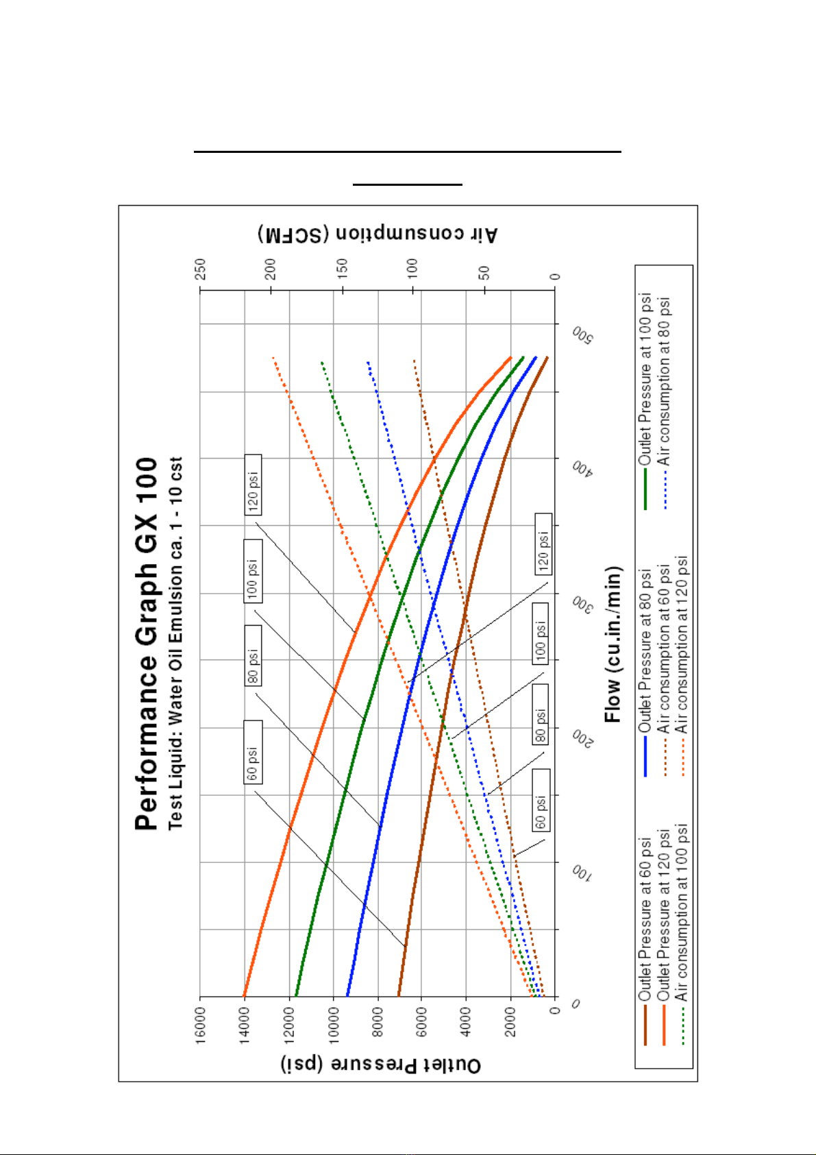
1.7
Performance curve of MAXIMATOR pump
Type GX100

2. Mode of operation
As a rule, the pump may be operated in any position but the longest service life of
sealings is ensured when it is installed vertically.
2.1 Drive part
The drive part consists of an air cylinder (22), bottom cap (20), top cap (26) and
air piston (48) to which compressed air is admitted reciprocally that prompts it to
make an oscillating motion.
In its stop positions the air piston (48) actuates the pilot valve plungers (53,85).
These pilot valves control the servovalve (31) by means of compressed air.
The pump is driven with compressed air (other gases upon request). When
compressed air is employed as drive we recommend our maintenance unit,
consisting of a filter, water separator, shut-off valve, pressure controller and
master pressure gauge.
If the maintenance unit is not installed, a suitable filter with a 5 µm mesh should
be used.
A lubrificator is not required since the pump is treated with a high-performance
grease prior to shipment.
If a lubrificator is provided in the drive system, a silicon- and acid-free oil should
be used to avoid swelling of packing rings. A pump that is equipped with a
lubrificator may only be used in lubrificator-equipped systems.
2.2 Control part
The control part consists of the servovalve (31), and servovalve runner (35), all
accommodated in the servovalve casing (83).
The servovalve (31) is actuated with compressed air by the pilot valves (53,85). The
servovalve feeds drive air to the right or left side of the air drive piston (48).
Questo manuale è adatto per i seguenti modelli
2
Indice
Altri manuali MAXIMATOR Pompa dell'acqua

Manuali Pompa dell'acqua popolari di altre marche


Sykes AmeriPumps
Sykes AmeriPumps GP100M Guida alla risoluzione dei problemi

DUROMAX
DUROMAX XP WX Series Manuale utente

BRINKMANN PUMPS
BRINKMANN PUMPS SBF550 Manuale utente

Franklin Electric
Franklin Electric IPS Manuale utente

Xylem
Xylem e-1532 Series Manuale utente

Milton Roy
Milton Roy PRIMEROYAL Manuale utente