
MaxPower T Series Manuale utente
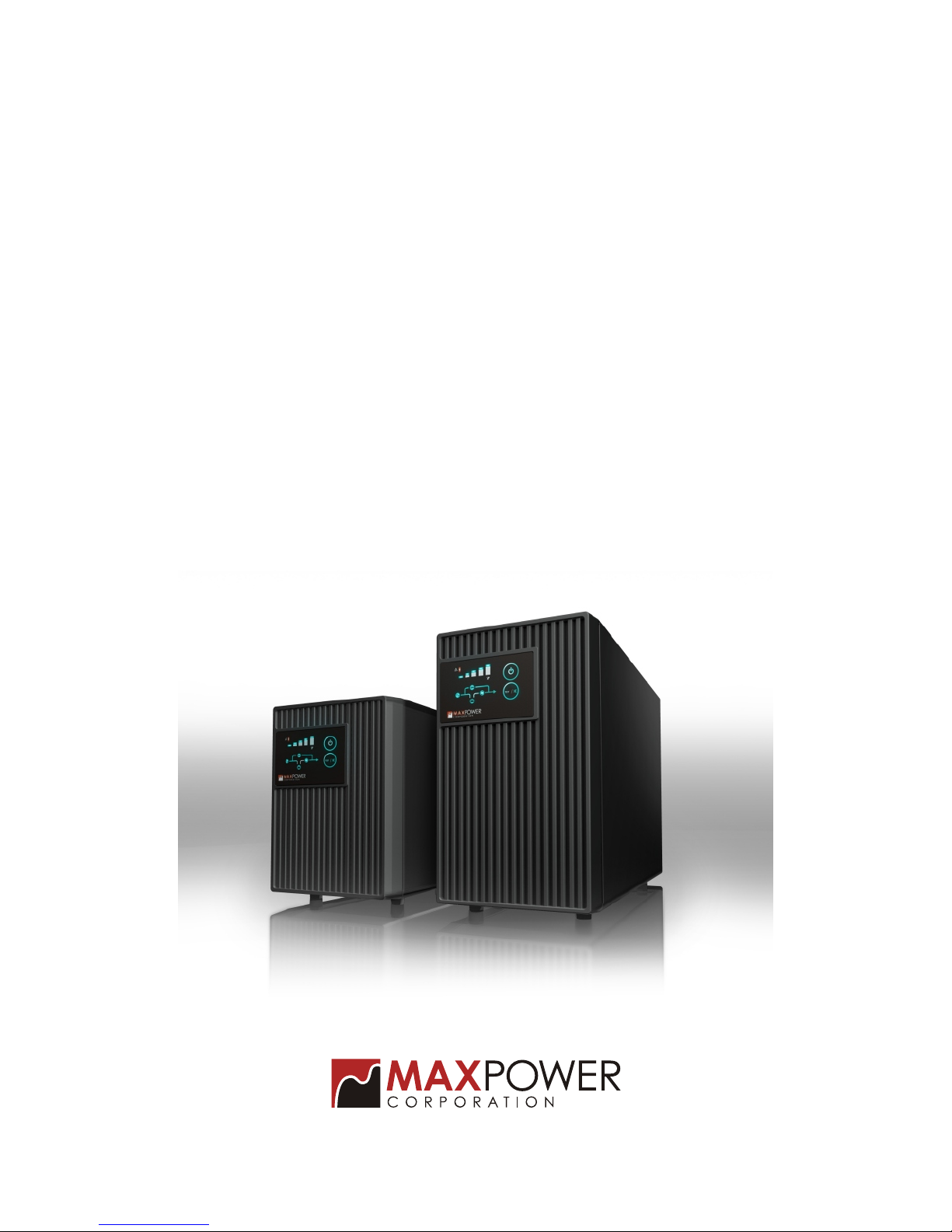
User's Manual
On-Line UPS
1000/2000/3000VA
MaxPower T Series

THIS MANUAL CONTAINS IMPORTANT SAFETY INSTRUCTIONS.
PLEASE READ THIS MANUAL THOROUGHLY BEFORE ATTEMPTING TO UNPACK.
INSTALL OR OPERATE THE UPS.KEEP IT HANDY FOR FUTURE REFERENCE.
Important Safety Instructions
Important Safety Instructions
* SAVE THESE INSTRUCTIONS- This manual contains important instructions that
should be followed during installation and maintenance of the UPS and batteries.”
* “ Intended for installation in a controlled environment.”
* “ The maximum ambient temperature is 25 Deg C.”
* “ Servicing of batteries should be performed or supervised by personnel
knowledgeable of batteries and the required precautions .Keep unauthorized
personnel away from battery.”
* “ CAUTION- To reduce the risk of fire, connect only to a circuit provided with 20
amperes maximum branch circuit overcurrent protection in accordance with the
national electric code, “ANSI/NFPA”. The marking may be located internally
adjacent to wiring terminals or provided in the instruction manual”.
* “ Proper selection of power supply cord listed,rated minimum 14A,125V,cord type
SJT , No.14AWG/3C,one end terminates in a listed grounding type terminates in a
cord connector, minimum1.8 m long”.
* “ This unit should be installed by service personnel.”
* “ The equipment can be operated by any individuals with no previous
experience.”
* “ The socket-outlet shall be installed near the equipment and easily accessible.”
* “ With the installation of this equipment it should be prevented ,that the sum of
the leakage current of the UPS and the connected consumer dose not exceed
3.5mA.”
* “ Attention,hazardous through electric shock.Also with disconnection of this
unit from the main,hazardous voltage still may be accessible through supply
from battery.The battery supply should be therefore disconnected in the plus
and minus pole thought from the outer enclosure accessible battery fuse
when maintenance or service work inside the UPS.”
CAUTION
CAUTION
- 1-

Important Safety Instructions
Radio Frequency Interference ( RFI ) Notice
This equipment generates,uses and canradiate radio frequencyenergy.If not
installed and usedin accordance withthe instructions,this unitmay cause
harmful interference toradio communications.However,thereis no guarantee
that interference willnot occur ina particular installation.Ifthis equipment does
cause harmful interferenceto radio ortelevison reception,which canbe
determined by turningthe equipment off and on,theuser is encouragedto try to
correct the interferenceby one ormore of thefollowing measures:
Reorient or relocatethe receiving antenna.
Increase the separationbetween the equipmentand the receiver.
Connect the equipmentinto an outleton a circuitdifferent from that to which
the receiver isconnected.
Consult with thedealer or anexperienced Radio /TVtechnician for help.
Safe and continuousoperation of theUPS depends partiallyon the caretaken
by users.Please observethe following precautions.
* Do notattempt to powerthe UPS fromany receptacle excepta 2-pole-3-wire
grounded receptacle.
* Do notplace the UPSnear water orin environments ofexcessive humidity.
* Do notallow liquid orany foreign objectsto get insidethe UPS.
* Do notblock air ventsin front ofthe UPS orair exhausts onthe back.
* Do notplace the UPSunder direct sunshineor close toheat-emitting
sources.
* Do notplug appliances suchas hair dryersinto the UPSreceptacles.
* Do notdisassemble the UPS.
* The power socket shouldbe installed nearthe equipment.It shouldbe easily
accessible to isolateit fromAC input.To disconnect,pull theplug from the
receptacle.
CAUTION
NOTE
- 2-

TableOf Contents
Table Of Contents
Important Safety Instructions
1. Introduction
1.1 System Description
1.2 Features
2. Installation andOperating Instructions
2.1 Unpacking & Inspection
2.2 Overview
2.3 Installation
2.4 Operation andFunctional Test
2.5 Manual Simulationof Power Outage for the UPS
2.6 Operating Parameter Setting
2.6.1 Configuration Mode
2.6.2 Display andControl Switch
2.6.3 End of configuration Mode
2.6.4 Setting of Parameters
2.6.4.1 Display ParameterConfiguration Stste
2.6.4.2 Cold Start Lock Setting
2.6.4.3 Output Frequency Setting
2.6.4.4 Output Voltage Setting
2.7 Operating Parameter Setting
3. Interface withComputer for UPS Status Monitoring
4. Service Maintenance
4.1 Routine Maintenance
4.2 Storage Instructions
5. Troubleshooting
6. Specifications
- 3-
4
4
4
5
5
5
7
9
9
10
10
10
11
11
11
11
12
13
13
17
18
18
18
19
22

The On-Line UPSare the mostupdated microprocessor-based digitalcontrolled
sinewave online uninterruptiblepower systems whichare designed toprovide the high
efficiency in normal mode operationand prevent anyspikes, surges, sagsand blackouts
from reaching yoursensitive equipment ,rangingfrom computer andtelecommunication
systems to computerizedinstruments.
1.Introduction
With the advancementin the informationtechnology, an increasing numberof server or
devices such asModem, Hub andRouter are susceptibleto surge andspike from common
utility coming throughthe telephone lineor LAN line;therefore, this seriesalso have
added surge andspike protection forRJ11 connection. Acomplete protection
design,easy management softwareand affordable price make thisseries the bestchoice
for protecting theserver.
The monitoring softwaredelivers data ofthe UPS operation,savesvital files
automatically on unattendedshutdown,schedules on oroff of the O/S ona daily orweekly
basis and logsin the statusof the UPSfor future reference.Itcan support multiple
operating systems.
Introduction
1.1 System Description
Double Conversion DesignProvides High Reliability and Efficiency.
High Frequency Designsto Lower theSize and Weight.
Intelligent Microprocessor Control.
True Sine Wave Output.
User Configurable OutputVoltage.
Smart Battery Reminder.
Self-Diagnostic Function canProvide Information forTroubleshooting Reference.
RJ11 Data/Fax Modem ConnectionProvides Surge Protection from Telephone.
True RS232 Signal for Power Management Software.
1.2 Features
- 4-
Examine the packingcarton for damageupon receipt.Once theUPS has beenremoved
from its shippingcontainer,everything insidethe package shouldbe inspected for
damage that mayhave occurred whilein transit .Notifythe carrier immediatelyif any
damage is observed.
The box shouldinclude the following:
2.Installation and Operating Instruction
2.1Unpacking&Inspection
* UPS andInput Power Cord
* User's Manual
* Telephone Communication Cable
* Remote MonitoringSoftware and ComputerSeries Interface Cable(optional)
Retain the packingfor future useor dispose ofproperly.
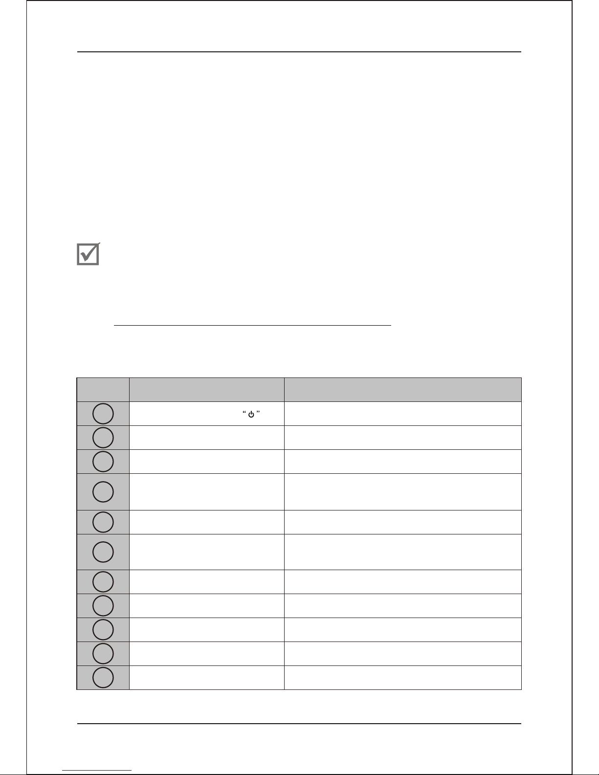
2.2Overview
Installation and OperatingInstruction
CHECK
Main On/OFF Switch
Beeper Silence andSelf-test
Capacity Indicator
Fault Indicator
Turn on/offUPS
UPS Silence andself-testing
LED bar showsapproximate load andbattery
Capacity (when inbattery backup)
Item Panel Indicator Description
1
2
3
4
5
6
7
8
9
10
11
AC Normal Indicator
AC Bypass ModeIndicator
Backup Mode/Battery Replace
Indicator
Output Indicator
External Battery Connector
(Extended models)
Input Circuit Breaker
DC Fan
Displays UPS Fault/ContinuousRed LED
Continuous Green LEDdisplays AC utility
normal
Continuous Amber LED displays AC Bypass
Mode
Continuous Red LEDdisplays Battery Replace
and Flash backupmode
Continuous Green LEDdisplays UPS Output
Provides connection portfor external battery
cable
Provides circuit overloadand fault protection
for the UPSand load
For air cooling
- 5-
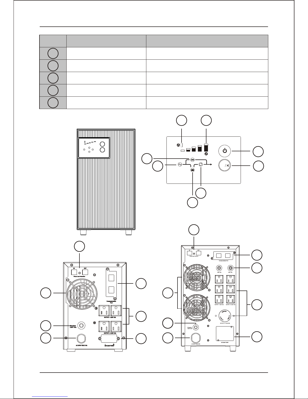
Item Panel Indicator Description
12
13
AC Inlet /Power cord
AC outlet
Date Port: RS232
Tel /Fax / Modem (Rj11)
14
15
16
Connect to inputpower cord
Connect to load
Communication Interface
Suppress the spikevoltage on thetelephone line
TEST
25% 50% 75% 100%
Battery
Load 1
2
3
4
5
8
7
6
Front Panel
120V Rear Panel
- 6-
Installation and OperatingInstruction
11
15
14
16
13
9
1010
12
15
14
11
10
12 9
13
Output Circuit Breaker Provides circuit overloadand fault protection
for the UPSand load
1000VA 2000VA/ 3000VA
2.3 Installation
Before installation, pleaseread and understandthe following instructions:
Placement
The UPS mustbe installed ina protected environment away from heat-emitting
appliances such asa radiator orheater. Do not install this product where
excessive moisture ispresent.
Ventilation
The location shouldprovide adequate airflow around the UPS with one inch
minimum clearance onall sides forproper ventilation.
Charge the Battery
Your new UPS may be used immediatelyupon receipt. Howevercharge loss
may occur duringshipping and storage.So charging the battery for at least 8
hours is recommendedto insure thatthe battery is fully charged.
Torecharge the battery, simply leavethe unit pluggedinto anAC outlet.
(This UPS willrecharge in boththe On and the Off status.)
- 7-
Installation and OperatingInstruction
15
14
11 11
10
12 9
13
15
14
13
9
10
12
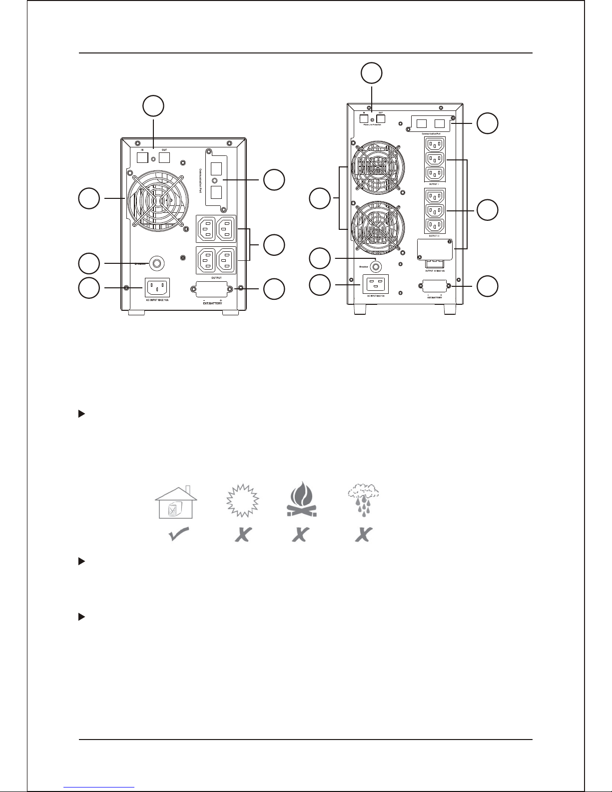
230V with IEC 320 Rear Panel
1000VA 2000VA/ 3000VA
- 8-
Installation and OperatingInstruction
Connect to AC
Make sure thatthe voltage andfrequency are correct.Plug the UPSinto a 2
pole,3 wire groundingreceptacle(wall outlet).Make surethe wall outletbranch
is protected.Avoid using extension cords atall possible. ifused, make sure
the extension cordis rated for15 Amps.
For 220/230/240V versions:swap the inputpower cord ofthe equipment tothe
inlet of UPS.Use the powercord supplied withthe UPS toconnect from the
outlet of theUPS to yourequipment.
Determining the Load:
1. Make alist of allequipment that requiresprotection.
2.Calculate thesum of allthe V xAratings.(Input voltage/current shownon
name plate).
3.Ensure thatthe total VA ratingdoes not exceedthe rated capacityof the
UPS.
If rated unitcapacities are exceeded,an overload conditionmay occur and
cause the UPSunit to shutdown or thecircuit breaker totrip.
Do not pluga laser printeror copy machineinto the outletsof this UPS.
The power demandsof these particulardevices are much higher than typical
peripherals.
NOTE
Connect the Load
Plug your primaryequipment(e.g: computer,monitor, criticaldata storage
device, etc.)into theBattery Power Protectedoutlets. Leave thepower
switches of theequipment in the“Off” position for the moment.
Connect to Computer
Use the enclosedRS-232 (DB9)cable. Plugthe 8-pin colorlessmale end intothe UPS.
Plug the 9-pinfemale end intoan open COMport on thecomputer (9-pin
Male).
Connect the Fax Lines
Toprotect a faxconnect the telephonecable from thewall outlet tothe “IN” jackof the
UPS. Connect thetelephone cable fromthe “OUT “phone outlet onthe UPS tothe fax.
The phone jackson the UPSaccept standard sizedphone cables (RJ11
communication cables ).
Please check withyour local dealerfor the monitoringsoftware.

Use the testfunction to checkboth the operationof the UPS and
the condition ofthe battery.
In AC operating mode,the level indicator will showthe actual load
connected to thisUPS normally.Pressand hold the "Test" switch
on the frontpanel for more than 2 seconds,this UPS will enter into
testing mode. Thebattery will provide power to the load during this
period.Testing mode will check thestatus of battery and operation
of UPS,last for10 seconds andtransfer back to normal status
automatically.
Testing modecan not performed if the load connected is greater
than overload orthe charging voltage is lower than
22Vdc (model:700W/1000VA)or 88Vdc (model:2100W/3000VA).
NOTE
Test
In battery backupmode, the level indicator will show the battery
capacity level andthe alarm beeps normally. Pressand hold the
" Test"switch on thefront panel for more than 2seconds. The
alarm will besilenced. The alarm can be activated again by
repeating the sameprocedure show in this paragraph. Under
silence model, presssilence key , the alarm will be silent. When
it happens lowbattery , overload or second utility power cut off,
the alarm silencewill be activated again.
Alarm Silence
Totest the backupfunction, you mayunplug the power cord of the UPS or simply press
the main switchbutton on thefront panel. The UPS will beep once every 4 seconds and
the backup modeLED will turnon. You can press the main switch again to silence the
audible alarm.
2.5 Manual Simulation of Power Outage for the UPS
- 9-
Installation and OperatingInstruction
AC Mode
The UPS deliverspower to theloads derived fromthe utility andmaintains proper
battery charge. Italso regulates theoutput voltage towithin a narrowrange and
serves to isolatethe load fromsurges and electricalnoise brought bythe utility wiring.
On-Battery Mode
The UPS operateson battery whenthe line voltageor frequency hasfallen outside
the limits. Localusers are alertedto this modeof operation byvisual and audible
indicators. The UPS provides powerto the loadfrom the batteryand through its
inverter and theoutput voltage andfrequency of theUPS are regulatedwithin a
narrow band.
2.4 Operation andFunctional Test
Function Panel Indicator
Switch On
press and holdthe main switch on the frontpanel for more than 2
seconds until the"AC normal" green LED lights up/"Bypass"
Amber LED lights up/"Inverter "green LED lights up. The UPS will
perform a self-testevery time it is switched on.
Indice
Manuali UPS popolari di altre marche

Pylontech
Pylontech Victron & Pylontech US5000 Manuale utente

Tecnoware
Tecnoware EVO DSP PLUS MM 6.8 Manuale utente

Mecer
Mecer ME-1000-WTU Manuale utente

Mustek
Mustek PowerMust 530(B) Plus Manuale di installazione e funzionamento

Emerson
Emerson Liebert NXL series Manuale utente

MAKELSAN
MAKELSAN BOXER SERIES Manuale utente


