
McLean Cooling Technology ProAir CR29 Manuale utente

© 2011 Pentair Technical Products 89055732
Rev. D P/N 10-1008-121
Protecting Electronics.
Exceeding Expectations.™
Pentair Technical Products
INSTRUCTION MANUAL
PROAIR
Air Conditioner
CR29

© 2011 Pentair Technical Products 89055732
- 2 -
TABLE OF CONTENTS
RECEIVING THE AIR CONDITIONER .............................................................................................................................................................. 3
HANDLING AND TESTING THE AIR CONDITIONER ................................................................................................................................. 3
INSTALLATION INSTRUCTIONS ..................................................................................................................................................................... 4
SYSTEM CONTROLS .......................................................................................................................................................................................... 4
Level I Temperature Controller ............................................................................................................................................................. 4
Level II and III Temperature Controller ............................................................................................................................................... 4
TECHNICAL INFORMATION ............................................................................................................................................................................ 5
DESIGN DATA............................................................................................................................................................................................... 5
DIMENSION DRAWING ............................................................................................................................................................................. 5
CR29 Models 2200-4000 BTU/Hr. (645-1172 Watt) ................................................................................................................ 5
Mounting Gasket Kit ................................................................................................................................................................................. 6
Design Notes ....................................................................................................................................................................................... 6
Mounting Cutout Dimensions .............................................................................................................................................................. 6
Components List ........................................................................................................................................................................................ 7
Parts List ........................................................................................................................................................................................................ 7
Wire Diagrams and schematics ............................................................................................................................................................ 8
Wire Diagram, Level 1, 2000 BTU ................................................................................................................................................. 8
Wire Diagram, Level 1, 4000 BTU ................................................................................................................................................. 9
Wire Diagram, Level II and III, 2000 BTU ..................................................................................................................................10
Wire Diagram, Level II and III, 4000 BTU ..................................................................................................................................12
TEMPERATURE CONTROL .............................................................................................................................................................................14
PRINCIPLES OF OPERATION .........................................................................................................................................................................14
MAINTENANCE .................................................................................................................................................................................................14
Compressor ...............................................................................................................................................................................................14
Inlet Air Filter .............................................................................................................................................................................................14
How To Remove, Clean or Install a New Inlet Air Filter ..............................................................................................................15
Condenser and Evaporator Air Movers ............................................................................................................................................15
Refrigerant Loss........................................................................................................................................................................................15
TROUBLE SHOOTING ......................................................................................................................................................................................16
Basic Air Conditioning Trouble Shooting Check List ..................................................................................................................16
Symptoms and Possible Causes: ........................................................................................................................................................17
WARRANTY ........................................................................................................................................................................................................18
RETURN AND REPAIR POLICY ......................................................................................................................................................................18
LIMITATION OF LIABILITY ..............................................................................................................................................................................19
© 2011 Pentair Technical Products89055732 - 3 -
RECEIVING THE AIR CONDITIONER
Inspect the air conditioner. Check for concealed damage that may have occurred during shipment. Look for dents,
scratches, loose assemblies, evidence of oil, etc. Damage evident upon receipt should be noted on the freight bill.
Damage should be brought to the attention of the delivering carrier -- NOT to McLean Cooling Technology -- within 15
days of delivery. Save the carton and packing material and request an inspection. Then le a claim with the delivering
carrier.
Pentair Technical Products cannot accept responsibility for freight damages; however, we will assist you in any way
possible.
HANDLING AND TESTING THE AIR CONDITIONER
If the air conditioner has been in a horizontal position, be certain it is placed in an upright, vertical or mounting
position for a minimum of ve (5) minutes before operating.
Do not attempt to operate the air conditioner while it is horizontal
or on its side, back or front. The refrigeration compressor is lled
with lubricating oil. This will cause permanent damage to the air
conditioner and also voids the warranty.
CAUTION
TEST FOR FUNCTIONALITY BEFORE MOUNTING THE AIR CONDITIONER TO THE ENCLOSURE.
Refer to the nameplate for proper electrical current requirements, and then connect the power cord to a properly
grounded power supply. Minimum circuit ampacity should be at least 125% of the amperage shown in the design
data section for the appropriate model. No other equipment should be connected to this circuit to prevent
overloading.
Operate the air conditioner for ve (5) to ten (10) minutes. No excessive noise or vibration should be evident during
this run period. The condenser blower (ambient air), the evaporator blower (enclosure air), and the compressor should
be running.
Condenser air temperatures should be warmer than normal room temperatures within a few minutes.
The compressor is provided with automatic reset thermal overload protection. This thermo-switch is located and
mounted inside the plastic enclosure clipped to the compressor. The switch operates when the compressor overheats
due to clogged or dirty inlet air lter or if ambient air temperatures exceed nameplate rating or if enclosure dissipated
heat loads exceed the rated capacity of the air conditioner. The thermal overload switch will actuate and stop
compressor operation. The blowers will continue to operate and the compressor will restart after it has cooled to
within the thermal overload cut-in temperature setting.

© 2011 Pentair Technical Products 89055732
- 4 -
INSTALLATION INSTRUCTIONS
1. Inspect air conditioner and verify functionality before mounting the air conditioner, see HANDLING
AND TESTING THE AIR CONDITIONER on page 3.
2. Using the cutout dimensions shown in this manual, prepare the air “IN” and air “OUT” openings, and
mounting bolt hole pattern for the enclosure.
3. Using the gasket kit provided, install gaskets to air conditioner. See Mounting Gasket Kit on page 6 for
proper location.
4. Mount air conditioner on enclosure using mounting bolts and washers provided to secure unit to
enclosure. Allow unit to remain upright for a minimum of ve (5) minutes before starting. Caution! Air
conditioner must be in upright position during operation.
5. Refer to the top of the nameplate for electrical requirements. Connect the power cord to a properly
grounded power supply. Use of an extension cord is not recommended. Electrical circuit should be
fused with slow blow or HACR circuit breaker.
6. When the unit is equipped with an automatic temperature controller, the controller is preset at the
factory for your convenience and should not require adjustment.
SYSTEM CONTROLS
Level I Temperature Controller
The Level I controller is located inside the air conditioner.
To adjust, disconnect power to the air conditioner and
open the front panel by loosening the front panel screw.
Refer to Figure 2 on page 7 to locate the controller. Turn
the controller adjustment screw slot counter-clockwise
to increase and clockwise to decrease the temperature
set point, see Figure 1. The thermostat cooling set point is
indicated by the alignment of the adjustment screw slot
with the dial decal. After completing adjustment, close
the front panel and tighten the front panel screw. Restore
power to the air conditioner for operation.
Level II and III Temperature Controller
The Level II and III controller mounted on the air
conditioner front panel is factory set for standard
operation. All operating parameters are programmable
for custom applications. Refer to the Level II and III
programming and Operating Instruction Manual,
10-1008-161.
Figure 1
Level I control
CONTROLS COMPRESSOR
OFF
© 2011 Pentair Technical Products89055732 - 5 -
TECHNICAL INFORMATION
DESIGN DATA
Model Voltage Hz Phase BTU/Hr @
131 F/131 F
Amps @ 131
F/131 F
BTU/Hr @
95 F/95 F
Amps @
95 F/95 F
Max
Amb
Temp
°F/°C
Shipping
Weight
lb./kg
CR290216GXXX 115 50/60 1 2000/2200 7.4/7.4 1700/2000 7.0/6.0 131/55 98/44
CR290226GXXX 230 50/60 1 2500/2700 4.6/3.9 1900/2300 4.4/3.3 131/55 98/44
CR290416GXXX 115 50/60 1 3500/4000 13.5/13.5 2400/2800 10.7/9.6 131/55 118/54
CR290426GXXX 230 50/60 1 3500/4000 6.7/6.6 2400/2800 5.9/5.3 131/55 118/54
-XXX will be replaced with a three-digit number designating all desired options. Consult the factory for specic model numbers.
DIMENSION DRAWING
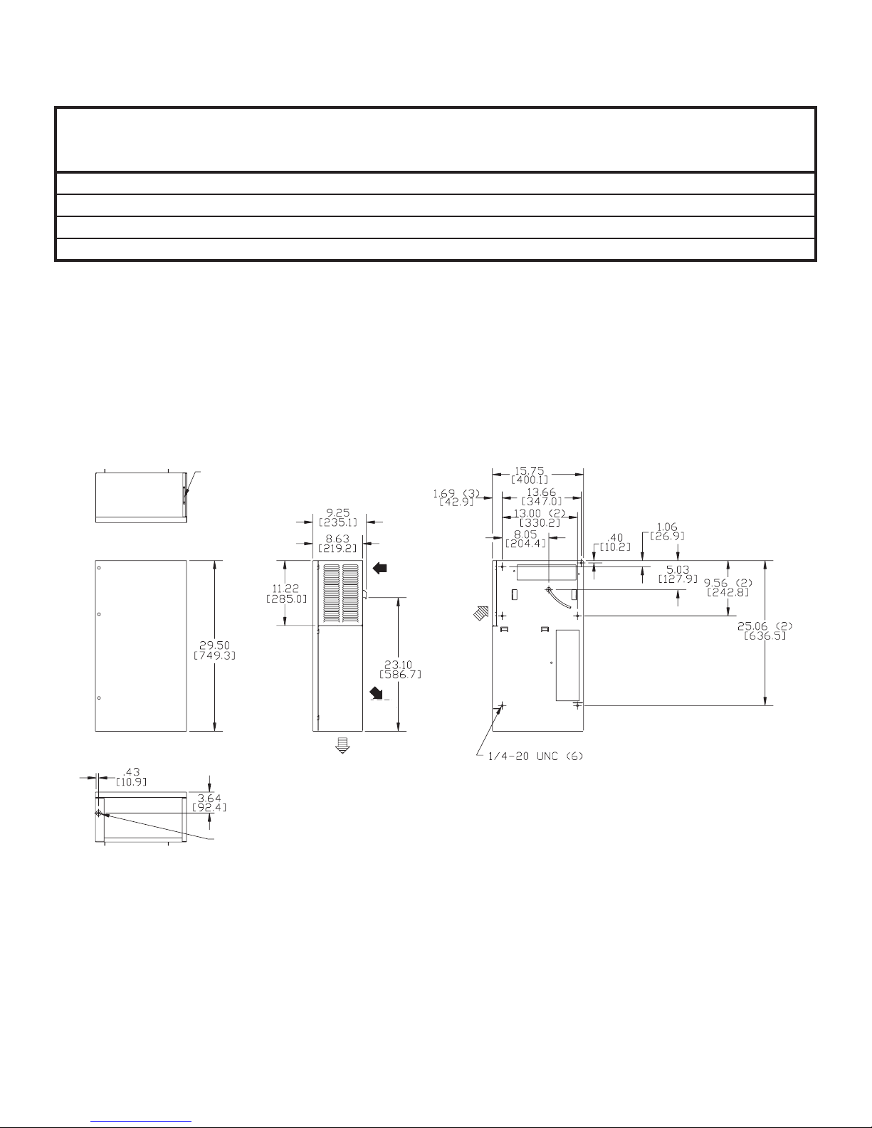
CR29 Models 2200-4000 BTU/Hr. (645-1172 Watt)
CLEANABLE, REUSABLE
ALUMINUM INLET FILTER
TOP VIEW
FRONT VIEW
SIDE VIEW BACK VIEW
AMBIENT
AIR OUT
COOL
AIR
OUT
AMBIENT
AIR IN
ENCLOSURE
AIR IN
BOTTOM VIEW
STANDARD
CONDENSATE
DRAIN LOCATION

© 2011 Pentair Technical Products 89055732
- 6 -
Mounting Gasket Kit
Design Notes
1. Gasket kit included. Apply gasket to rear
of air conditioner before mounting on
enclosure.
2. Service cord terminated with appropriate
plug cap.
3. Millimeter dimensions [ ] are for reference
only; do not convert to inch dimensions.
4. Allow at least 4 inch inlet and 6 inch
outlet clearance for proper ambient
air ow. Allow 20 inch above lter for
removal.
Mounting gasket kit part no. 29-4100-02 as applied to
rear of CR29.
Mounting Cutout Dimensions
1. DASHED LINES REPRESENT OUTSIDE OF AIR CONDITIONER
NOTE:
Cutout Instructions

© 2011 Pentair Technical Products89055732 - 7 -
Components List
Part Description 115 Volt
2200
115 Volt
4000
230 Volt
2700
230 Volt
4000
Blower, Condenser 29-4121-10 29-4121-10 29-4120-10 29-4120-10
Blower, Evaporator 29-4121-10 29-4121-10 29-4120-10 29-4120-10
Capacitor, Compressor N/A 10-1032-13 10-1032-09 10-1032-14
Compressor 10-1016-23 SP 10-1016-26 SP 10-1026-74 SP 10-1026-77 SP
Thermal Overload, Compressor 10-1007-19 10-1007-45 10-1007-57 10-1007-51
Filter, Air, Reusable 10-1000-32 10-1000-32 10-1000-32 10-1000-32
Thermostat, SPST, 55-100F 10-1061-16 10-1061-16 10-1061-16 10-1061-16
Mounting Gasket Kit 29-4100-02 29-4100-02 29-4100-02 29-4100-02
Relay, Compressor 10-1028-20 10-1028-14 10-1028-07 10-1028-15
Power Cord Consult factory Consult factory Consult factory Consult factory
Parts List
Part Description Part No.
1 Condenser Coil 29-4101-00
2 Filter, drier, refrigerant 52-6028-00
3 Compressor See Components List
4Hot Gas bypass valve
(CR29-04xx units only) 52-6027-11
5 Evaporator coil 29-4102-00
6Inlet air lter,
reusable aluminum 10-1000-32
7Blower (115V)
Blower (230V)
29-4121-10
29-4120-10
8Compressor thermal
overload switch See Components List
9Capacitor, compressor
(CR29-04xx units only) See Components List
10 Capacitor, compressor
(CR29-0226 units only) See Components List
11 Terminal block 086912
12 Power cord Consult Factory
13 Temperature controller Consult Factory
14 Relay, compressor
(CR29-04xx units only) See Components List
15 Relay, compressor
(CR29-02xx units only) See Components List
16 Mounting gasket kit 29-4100-02
Figure 2

© 2011 Pentair Technical Products 89055732
- 8 -
Wire Diagrams and schematics
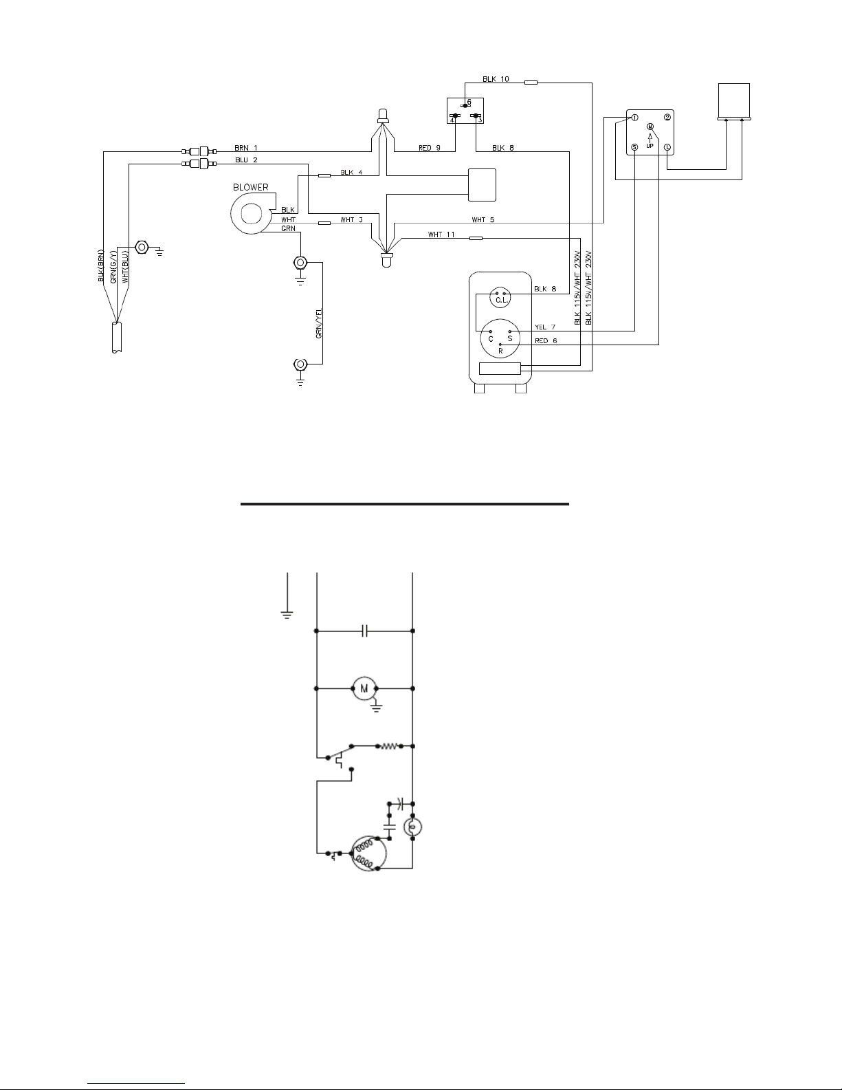
Wire Diagram, Level 1, 2000 BTU
SERVICE CORD
DOOR STUD
SUPPRESSOR
SUPPRESSOR
BLOWER
COMPRESSOR
LINE
THERMOSTAT
THERMOSTAT
COMPRESSOR HEATER (OPTIONAL)
ELECTRICAL SCHEMATIC
COMPRESSOR
HEATER
(OPTIONAL)
MALFUNCTION
SWITCH
(OPTIONAL)
START RELAY,
COMPRESSOR AND
OVERLOAD
© 2011 Pentair Technical Products89055732 - 9 -
Wire Diagram, Level 1, 4000 BTU
NOTE: For voltage, hertz, and options not shown in this manual, refer to the wiring diagram
attached to the unit.
SERVICE CORD
DOOR STUD
SUPPRESSOR
SUPPRESSOR
BLOWER
COMPRESSOR
LINE
THERMOSTAT
THERMOSTAT
COMPRESSOR HEATER (OPTIONAL)
ELECTRICAL SCHEMATIC
COMPRESSOR
HEATER
(OPTIONAL)
RELAY
START
CAPACITOR
COMPRESSOR AND
OVERLOAD
START RELAY
START CAPACITOR
© 2011 Pentair Technical Products 89055732
- 10 -
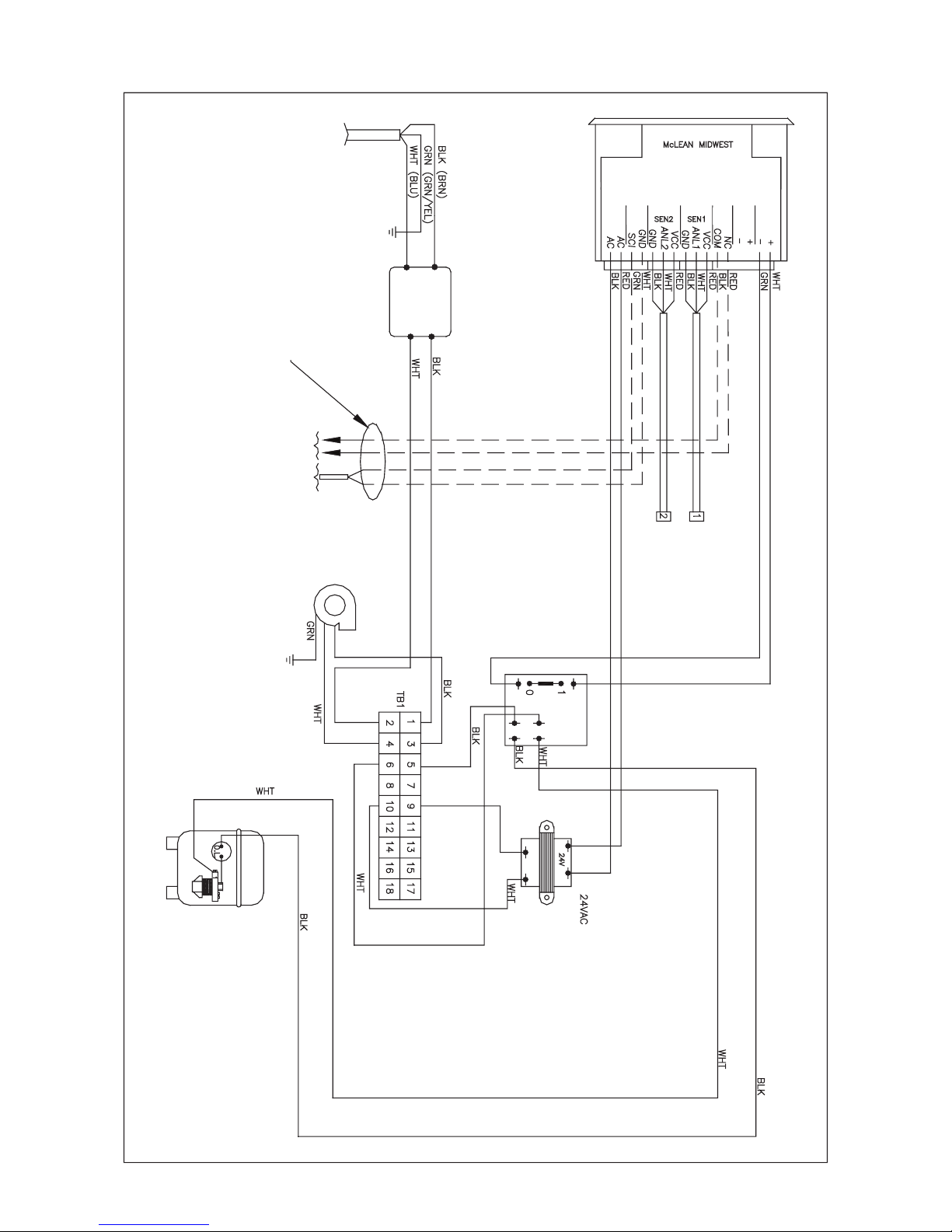
Wire Diagram, Level II and III, 2000 BTU
FIELD WIRED BY
CUSTOMER
BLOWER
COMPRESSOR
RELAY
TRANSFORMER
TEMPERATURE SENSOR
ENCLOSURE
TEMPERATURE SENSOR
AMBIENT AIR INLET
WIRING DIAGRAM
EMI
FILTER
ALARM OUTPUT NORMALLY
CLOSED
CONTROLLER
MODEL
DATE CODE
POWER
ALARM
IN
ALARM
OUT HEAT HEATCOOL
ALARM INPUT NORMALLY CLOSED
Indice
Altri manuali McLean Cooling Technology Condizionatore d'aria

McLean Cooling Technology
McLean Cooling Technology LOBOY 16 Manuale utente

McLean Cooling Technology
McLean Cooling Technology ProAir CR43 Manuale utente

McLean Cooling Technology
McLean Cooling Technology T15 Manuale utente

McLean Cooling Technology
McLean Cooling Technology Genesis M13-0116-G1014 Manuale utente

McLean Cooling Technology
McLean Cooling Technology SPECTRACOOL G28 1-Phase Manuale utente


