
McQuay LIA265-1 Guida utente
Installation, Operation & Application Guide
LIA265-1
Group: WSHP
Supercedes: LIA217
Date: 12-19-08
Programmable Electronic Thermostat
2 Heat/2 Cool, 7-Day Programmable, Hardwired
Part No. 668375301
For replacement parts call 1-800-377-2787
©2008 McQuay International • www.mcquay.com • 800-432-1342
• Programmable and Congurable
• Single/Dual Stage Heat/Cool Systems
• Backlit Display
• Auto Changeover
• Simpleset® 7 Day Programming
• Title 24 Compliant/No Batteries Required
• Relay Outputs (minimum voltage drop in thermostat)
• Ideally Suited for:
– Light Commercial/Residential (New Construction/Replacement)

Table of Contents
Specications 1
ImportantSafetyInformation 1
PackageContents/ToolsRequired 1
ToRemoveExistingThermostat 2
ToInstallThermostat 2
RemoteSensorInstallation(Optional) 4
TerminalDesignatorDescriptions 5
WiringDiagrams 5
CongurationMode 7
TestingtheThermostat11
ModeofOperation12
OperatingModes 13
SettingtheTimeandDayoftheWeek 14
Programming15
Simpleset®Programming17
LockoutFeature17
FactoryPreprogramming 18
PersonalProgramSchedule 18
ShippingCongurationSettings20
Troubleshooting21

1
Electrical rating: • 24 VAC/VDC (18-30 VAC/VDC)
• 1 amp maximum per terminal
• 4 amp maximum total load
Temperature control range: 45°F to 90°F (7°C to 32°C) Accuracy: ± 1°F (± 0.5°C)
System configurations: 2-stage heat, 2-stage cool
Terminations: -C, +R, W1, Y1, W2, Y2, G, S1, S2
Specications
WARNING!
:Always turn off power at the main power supply before installing, cleaning, or removing
thermostat.
• This thermostat is for 24 VAC/VDC applications only; do not use on voltages over 30 VAC/VDC
• Do not short across terminals of gas valve or system control to test operation; this will damage your
thermostat and void your warranty
• All wiring must conform to local and national electrical and building codes
• Do not use air conditioning when the outdoor temperature is below 50 degrees; this can damage your
A/C system and cause personal injuries
• Use this thermostat only as described in this manual
Important Safety Information
Package includes: McQuay programmable thermostat on base, labeled thermostat cover, wiring
labels, screws and wall anchors, Owner’s Manual, Installation, Operation and
Application Guide.
Tools required for installation: Drill with 3/16” bit, hammer, screwdriver.
Package Contents/Tools Required

2
ELECTRICAL SHOCK HAZARD – Turn off power at the main service panel by removing the fuse
or switching the appropriate circuit breaker to the OFF position before removing the existing
thermostat.
1. Turn off power to the heating and cooling system by removing the fuse or switching the appropriate
circuit breaker off.
2. Remove cover of old thermostat. This should expose the wires.
3. Label the existing wires with the enclosed wire labels before removing wires.
4. After labeling wires, remove wires from wire terminals.
5. Remove existing thermostat base from wall.
6. Refer to the following section for instructions on how to install this thermostat.
To Remove Existing Thermostat
ELECTRICAL SHOCK HAZARD – Turn off power at the main service panel by removing the fuse
or switching the appropriate circuit breaker to the OFF position before removing the existing
thermostat.
IMPORTANT: Thermostat installation must conform to local and national building and electrical
codes and ordinances.
Note:
Mount the thermostat about five feet above the floor. Do not mount the thermostat on an
outside wall, in direct sunlight, behind a door, or in an area affected by a vent or duct.
1. Turn off power to the heating and cooling system by removing the fuse or switching the appropriate
circuit breaker off.
To Install Thermostat

3
To Install Thermostat (continued)
2. To remove cover, insert and twist a coin or screwdriver in the slots on the sides of the thermostat.
3. Put thermostat base against the wall where you plan to mount it (Be sure wires will feed through the
wire opening in the base of the thermostat).
4. Mark the placement of the mounting holes.
5. Set thermostat base and cover away from working area.
6. Using a 3/16” drill bit, drill holes in the places you have marked for mounting.
7. Use a hammer to tap supplied anchors in mounting holes.
8. Align thermostat base with mounting holes and feed the control wires through wire opening.
9. Use supplied screws to mount thermostat base to wall.
10. Insert stripped, labeled wires in matching wire terminals. See “Wiring Diagrams” section of this
manual (Pages 5 & 6). If using optional remote sensor, see “Remote Sensor Installation” (Page 4).
CAUTION!
:
Be sure exposed portion of wires does not touch other wires.
11. Tighten screws on terminal block. Gently tug wire to be sure of proper connection. Double check that
each wire is connected to the proper terminal.
12. Seal hole for wires behind thermostat with non-flammable insulation or putty.
13. Replace cover on thermostat by snapping it in place.
14. Turn on power to the system at the main service panel.
15. Test thermostat operation as described in “Testing the Thermostat” (Page 11).

4
1. Remove cover from remote sensor housing.
2. Select an appropriate location for mounting the remote sensor.
3. Mount remote sensor unit using hardware provided.
4. Install two strand shielded wire between remote sensor and thermostat. Shielded wire must be used.
Do not run remote sensor wire in conduit with other wires.
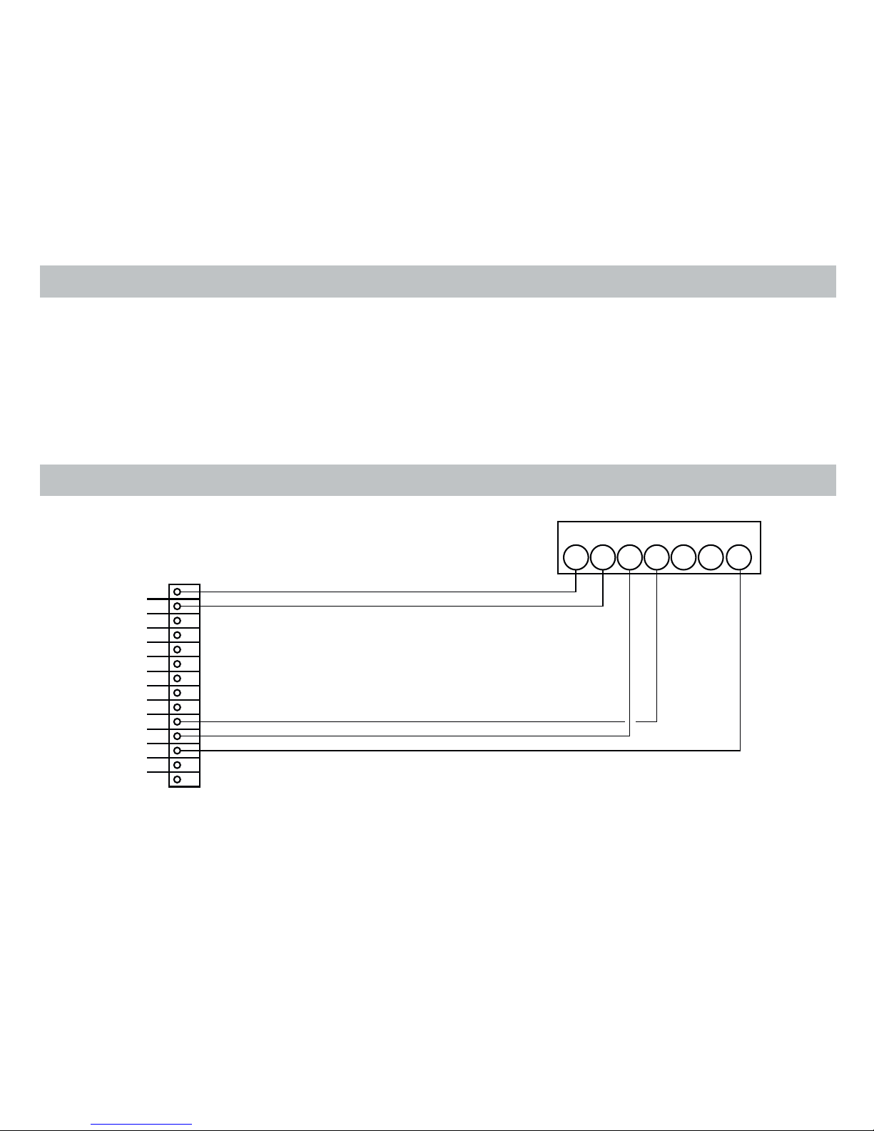
• Wire 1 should run between the S1 terminal on the thermostat and the S1 terminal on the
remote sensor
• Wire 2 should run between the S2 terminal on the thermostat and the S2 terminal on the
remote sensor
• Connect the shielding of the wire to the S2 terminal on the thermostat
5. Disable the main sensor (R12) on the thermostat by cutting it from the circuit board.
Remote Sensor Installation (Optional)
Requires McQuay Remote Sensor Part Number 667720401
5
-C Y2W2Y1W1+R
ELECTRONIC THERMOSTAT
W
2
G W
1
Y
1
F E L U A P V +
R
-
C
O
McQUAY SINGLE CIRCUIT
Mark IV Board
Low Voltage Terminal Board
Terminal Designator Descriptions
Wiring Diagrams
G

6
-C GY2W2Y1W1+R
McQUAY DUAL CIRCUIT
Mark IV Board Circuit 1
Low Voltage Terminal Board
Mark IV Board Circuit 2
Low Voltage Terminal Board
ELECTRONIC THERMOSTAT
W
2
G W
1
Y
1
F E L U A P V +
R
-
C
O
W
2
G W
1
Y
1
F E L U A P V +
R
-
C
O

7
The configuration mode is used to set the SC3801 to match your heating/cooling system. The SC3801 functions
with heat pump, air conditioning, gas, oil, or electric heat systems.
1. To enter the configuration mode, simultaneously hold down the and buttons while the
SC3801 is in OFF mode.
2. Press the or button to change settings within each screen.
3. Press the button to advance to the next screen.
Note: The button will return you to the previous screen.
4. To exit configuration mode, hold in the button for 6 seconds.
Configuration Mode Settings
The setup screens for configuration mode are as follows:
1. Heat pump – Press the or button to configure as heat pump or non-heat pump system.
• ON = Heat pump system
• OFF = Non-heat pump system
Press the button to advance to the next screen.
2. Reversing valve – appears only if heat pump is set to “ON”.
Press the or button to set reversing valve.
If your reversing valve is energized in heat mode, set to “b.” If the reversing valve is
energized in cool mode, set to “o.”
Press the button to advance to the next screen.
3. HEAT, ELECTRIC, or GAS/OIL – appears only if heat pump setting is “OFF”.
Press the or button to set heat type.
• For electric heat (interlocked), set “ELC” ON
• For gas or oil heat (non-interlocked), toggle “ELC” OFF
Press the button to advance to the next screen.
Conguration Mode

8
Configuration Mode Settings (continued)
5. Stage 1 Differential (1°F to 3°F) (1°C to 2°C) – Set the number of degrees between your “turn
on” temperature and your “setpoint” temperature.
Press the or button to set differential value.
Press the button to advance to the next screen.
7. Deadband (1°F to 9°F) (1°C to 5°C) – Set the minimum number of degrees between your
heating system activation and your cooling system activation.
Press the or button to set deadband value.
Press the button to advance to the next screen.
6. Stage 2 Differential (1°F to 6°F) (1°C to 3°C) – Set the number of degress between when Stage
1 turns on and when Stage 2 turns on.
Press the or button to set differential value.
Press the button to advance to the next screen.
4. Temperature scale (F or C) – Choose Fahrenheit or Celsius.
Press the or button to select.
Press the button to advance to the next screen.
8. Staged off outputs – Select whether the outputs for heating and cooling are staged off
independently or are satisfied simultaneously.
1 = Economy Mode – Outputs are staged on and off in accordance with setpoint and
differential.
0 = Comfort Mode – Outputs are staged on and all stages cycle off simultaneously when set
point is satisfied.
Press the or button to select.
Press the button to advance to the next screen.
9. Fan ON Delay – HEAT cycle (0-120 seconds) – Time fan is delayed turning ON at start of heat
cycle. For no delay, set to 0:00 (appears only for heat pump or electric heat systems).
Press the or button to set delay.
CAUTION!: Changing from the default of 0:00 may permanently damage your system.
Press the button to advance to the next screen.
Questo manuale è adatto per i seguenti modelli
1
Indice
Altri manuali McQuay Termostato


