MediaForte SF256-PCP Manuale utente

User Manual
SF256-PCP
4-channels PCI Audio Board

User Manual
1
Read This First
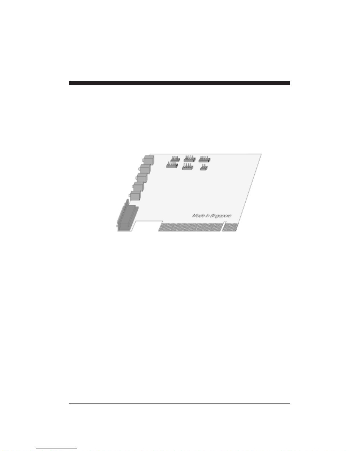
The following diagram describes the board layout and the various
connectors found on the SF256-PCP PCI sound card:
J5 J2 J3
Antenna In *
Line In
Mic In J4 J1 J6
Front Speaker
Rear Speaker
Game/MIDI
Port
Legend Description
J1 Auxiliary connector (optional)
J2 Video connector
J3 Telephone Answering Device connector
J4 CD Audio connector (2.54mm pitch)
J5 CD Audio connector (2mm pitch)
J6 PC Speaker connector
* Note that the connector for Antenna In is present only in
model SF256-PCP-R (with built-in FM Radio).
1-1Read This First
User Manual
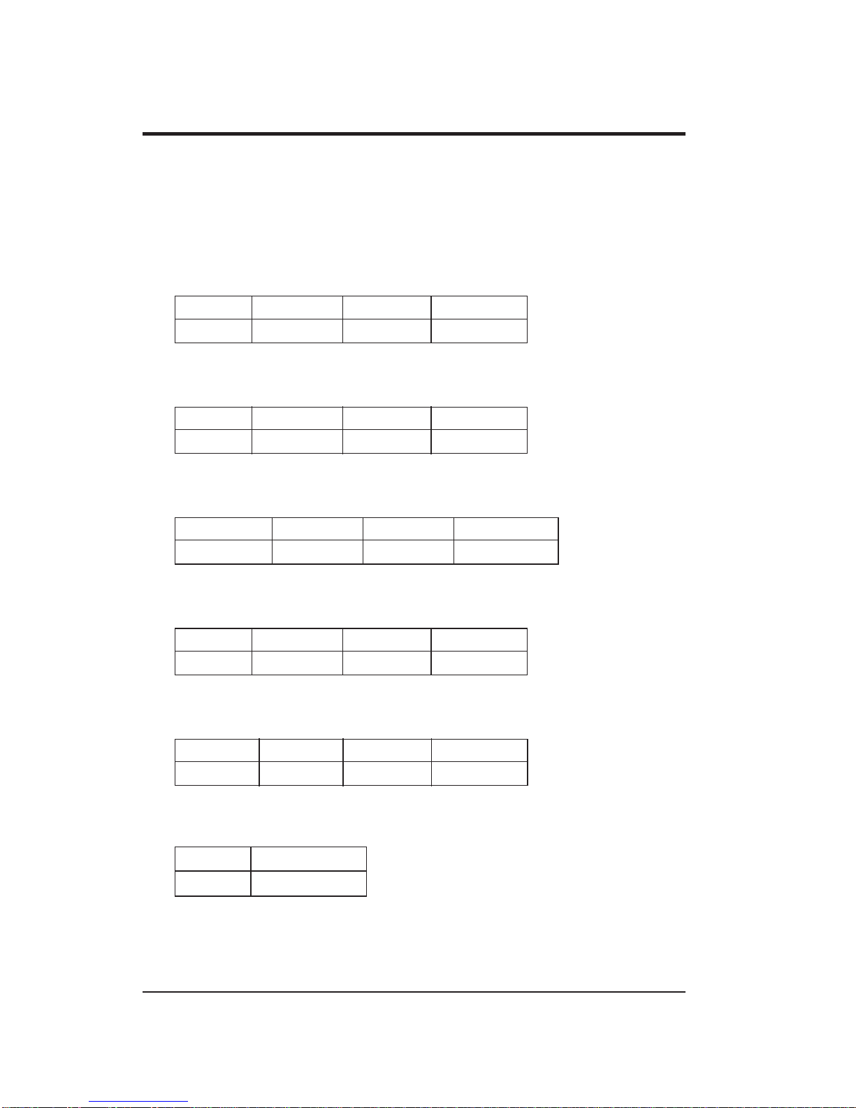
Pins configuration
The following shows the pins configuration of jumper J1, J2, J3,
J4, J5, and J6:
J1,AUX (optional)
Pin 1 Pin 2 Pin 3 Pin4
Left Ground Ground Right
J2, VIDEO
Pin 1 Pin 2 Pin 3 Pin4
Left Ground Ground Right
J3,TAD
Pin 1 Pin 2 Pin 3 Pin4
Mono-out Ground Ground Phone-in
J4, Sony CDAudio
Pin 1 Pin 2 Pin 3 Pin4
Right Ground Ground Left
J5, Mitsumi CDAudio
Pin 1 Pin 2 Pin 3 Pin4
Ground Right Ground Left
J6, PC Speaker
Pin 1 Pin 2
+5V PC Spk in
1-2

2
Setting Up SF256-PCP
To install the sound board:
1. Switch off your system and all peripheral devices.
2. Leave the power cable connected to the grounded outlet so
that your system is grounded.
3. Touch a metal plate on your system to ground yourself and
discharge any static electricity that might damage the
components on the board.
4. Remove the cover from your system.
5. Locate a free PCI slot in your system as shown below.
6. Remove the metal plate from the slot you have chosen and
put the screws aside.
7. Align the gold fingers on the board with the vacant
expansion slot and gently lower the board into the slot.
8. Secure the board to the expansion slot with the screws you
have removed from the metal plate.
9. Connect speakers to the audio output jack on your sound
board.
Note: If your package comes with a CD-ROM drive, do
not replace the system cover until you have installed
the drive in your system.
10.Replace the cover of your system and switch it on.
Setting Up SF256-PCP 2-1

User Manual
Minimum System Requirements
FPentium 133MHz CPU
FMicrosoft DirectX version 5
F16MB RAM
(32MB if using 4MB sound library software wavetable)
FMicrosoft Windows 95, Windows 98 or Windows NT 4.0
FActive speakers (connects to the Front speaker jack)
Positioning Your Sound Speaker
This section decribes how to position two pairs of powered
speakers or external amplifier speakers for best surround-sound
effect. Connect one pair to the Front Speaker Jack (on the sound
board) and identify this pair as Front Speakers. The other pair
should connects to the Rear Speaker Jack and is identified as Rear
Speakers.
Position your Front Speaker
and Rear Speakers such that
they form a square encircled
around you. Try to position
your speaker angled towards
you for best audio effect.
You may want to adjust the
relative positions of the
speakers until you get the audio
experience you like best.
If you have a subwoofer,
place this unit at the center
on the carpet floor or in a corner
of the room for best experience.
2-2
2-3Setting Up SF256-PCP
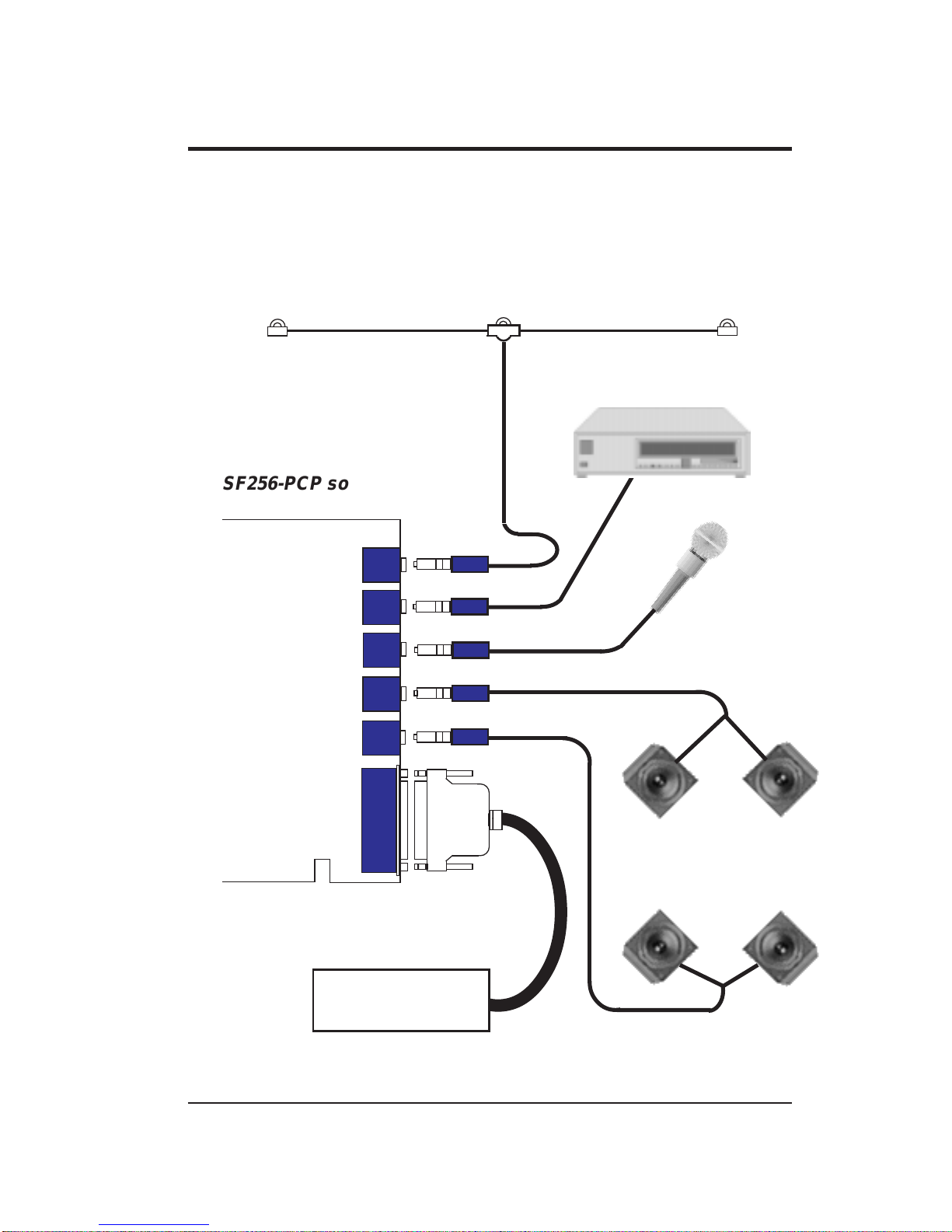
Connecting SF256-PCP to External Devices
The SF256-PCP PCI sound board allows you to connect it to
several other external devices as shown in the diagram below:
FM Dipole Antenna
Cassette and CD Player
Microphone
(CON6) GAMEPORT / MIDI
CONNECTOR
(CON5) ANTENNA
(CON1) LINE IN
(CON3) FRONT SPEAKER
(CON2) MIC IN
12
12
12
12
12
12
SF256-PCP sound board
(CON4) REAR SPEAKER
Joystick/
External MIDI devices
Multimedia
Stereo Power
Speakers

User Manual2-4
Line-In Jack, CON1
The Line-In Jack allows standard audio output from e.g. Hi-Fi
system, CD player or cassette deck, to be channelled into sound
board. This facilitates direct recording of external audio and also
the mixing of external audio with sound produced by the sound
board.
Mic Jack, CON2
The Mic Jack accepts both dynamic and electret condenser
microphones as voice input for recording and mixing.
Front Speaker Line-Out Jack, CON3
This Front Speaker Line-Out Jack connects to a pair of stereo
power speakers or any external amplifier for front audio output.
Rear Speaker Line-Out Jack, CON4
This Rear Speaker Line-Out Jack connects to another pair of
stereo power speakers or any external amplifier for rear audio
output.
Antenna Jack, CON5 (only for SF256-PCP-R model)
The antenna jack connects to a dipole anrenna for proper
reception of FM radio signals. The location or orientation of the
antenna may be adjusted for optimum reception.
This jack is only present on model SF256-PCP-R with built-in FM
Radio on board.
Game / MIDI Port, CON6
The D-sub connector serves two functions, namely for the
connection of a PC joystick and also for connecting external MIDI
instruments.

3
Installation Under Windows 95/98
This chapter guides you through the installation of the SF256-PCP
PCI sound board under Microsoft Windows 95/98 environment.
The installation is divided into two sections : Audio and FM radio
(optional feature only available on model SF256-PCP-R).
Installation of the Radio software is described in chapter 5.
Please verify that the sound card does not share resources with
legacy peripheral cards. Refer to the FAQ in the on-line manual to
"Resolve any Resource Conflicts".
Installation Under Windows 95/98
The various version of Windows 95/98 will display different
dialog boxes during installation. This manual assumes that you are
using Windows 98
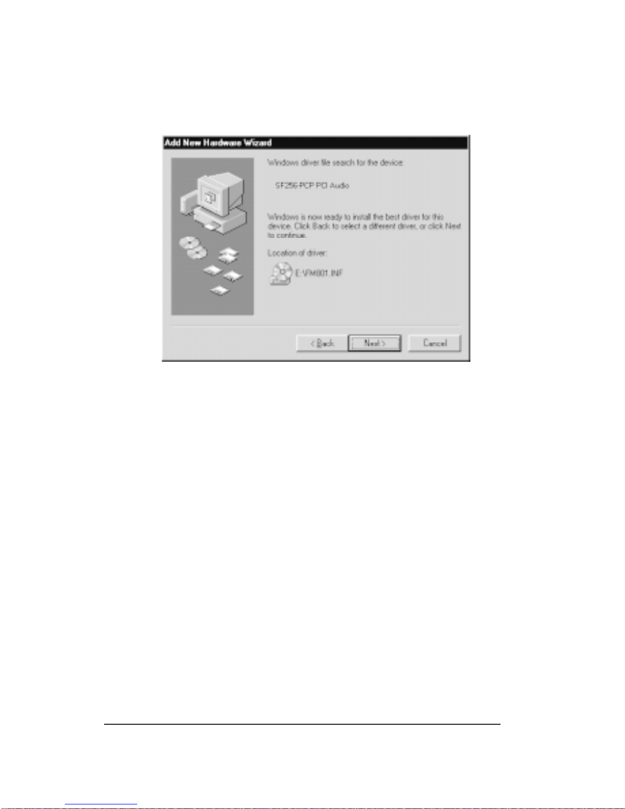
1. Upon starting the system for the first time after inserting the
SF256-PCP PCI Sound board, Windows will notify that it
has detected PCI Multimedia Audio Device.
2 Click Next.
3. In the next dialog box, select Search for the best driver for
your device. (Recommended) and click Next.
4. Select CD-ROM drive to install directly from D: drive or
select Specify a location: and Browse... to D:\ (where D: is
your CD-ROM drive.)
Installation Under Windows 95/98 3-1
User Manual
5. You will see the SF256-PCF PCI Audio/Game Device
detected as shown below:
6. Click Next and Windows will start copying files into your
harddrive.
7. Click Finish to complete the installation and reboot your
system.
3-2
Indice
Manuali Hardware per computer popolari di altre marche

EMC2
EMC2 VNX Series Manuale del proprietario

Panasonic
Panasonic DV0PM20105 Manuale utente

Mitsubishi Electric
Mitsubishi Electric Q81BD-J61BT11 Manuale utente

Gigabyte
Gigabyte B660M DS3H AX DDR4 Manuale utente

Raidon
Raidon iT2300 Manuale utente

National Instruments
National Instruments PXI-8186 Manuale utente


