Medva PW530 Manuale utente

SWING GATE OPENERS
FOR RESIDENTIAL
with limit switch & LED indicator
USER MANUAL
24V DC GEAR MOTOR
PW530
Flashing Light
Control box
Push Button
Gate 2
Gate 1


INSTRUCTIONS PW530 1
Index
1) Warnings
2) Product Description and Applications
2.1 General Information
2.2 Tools need for Installation
2.3 Installation
2.4 Cable Connection
2.5 Power Connection
3. Installation
3.1 Preparation for Motor Installation
3.2 Installation of the motor
3.3 Limit switch adjustment
3.4 LED Indicators
4) Technical Characteristics
4.1 PW530
4.2 PW530L
2
3
3
3
3
3
3
4
4
6
7
8
8
8
8
INSTRUCTIONS PW530
2
1) Warnings
Please read this instruction manual carefully before the
installation of gate-automated system.
This manual is exclusively for qualified installation
personnel. Powertech Electronics Inc. is not responsible for
improper installation and failure to comply with local
electrical and building regulations.
Keep all the components of PW530 system and this manual
for further consultation.
In this manual, please pay extra attention to the contents
marked by the symbol:
Be aware of the hazards that may exist in the procedures
of installation and operation of the gate-automated
system. Besides, the installation must be carried out in
conformity with local standards and regulations.
If the system is correctly installed and used following all
the standards and regulations, it will ensure a high degree
of safety.
Make sure that the gates works properly before installing
the gate-automated system and confirm the gates are
appropriate for the application.
Do not let children operate or play with the
gate-automated system.
Do not cross the path of the gate-automated system when
operating.
Please keep all the control devices and any other pulse
generator away from children to avoid the gate-automated
system being activated accidentally.
Do not make any modifications to any components except
that it is mentioned in this manual.
Do not try to manually open or close the gates before you
release the gear motor.
If there is a failure that cannot be solved and is not
mentioned in this manual, please contact qualified
installation personnel.
Do not use the gate-automated system before all the
procedures and instructions have been carried out and
thoroughly read.
Test the gate-automated system weekly and have
qualified installation personnel to check and maintain the
system at least every 6-month.
Install warning signs (if necessary) on the both sides of
the gate to warn the people in the area of potential
hazards.
INSTRUCTIONS PW530 3
2.1 General Information
2.3 Installation
The PW530 gate openers are applicable for 3.0/4.5 meters per leaf in width and 450/550 kg in weight and primarily
for residential use. The performance of PW530 will be influenced by the gate dimension, weight and climate.
The installation procedure of PW530 might be changed due to different accessories and quantities installed.
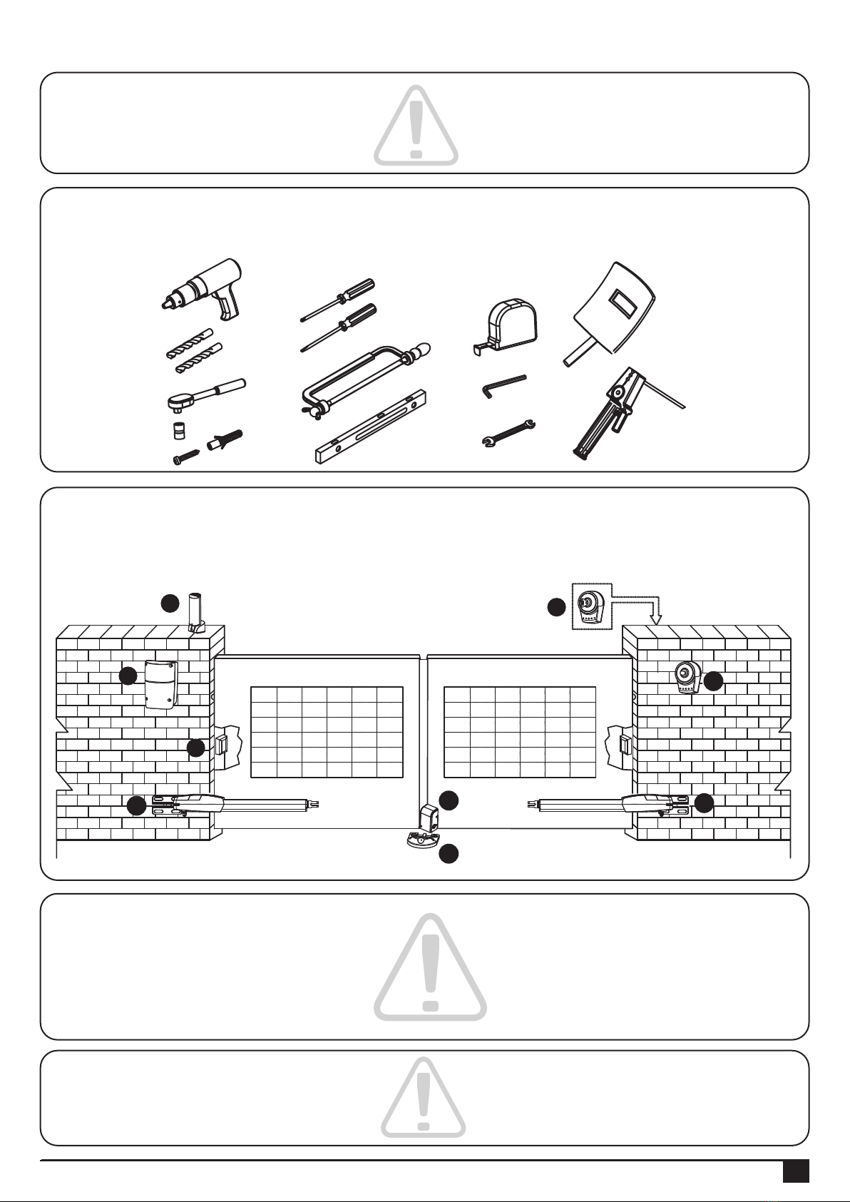
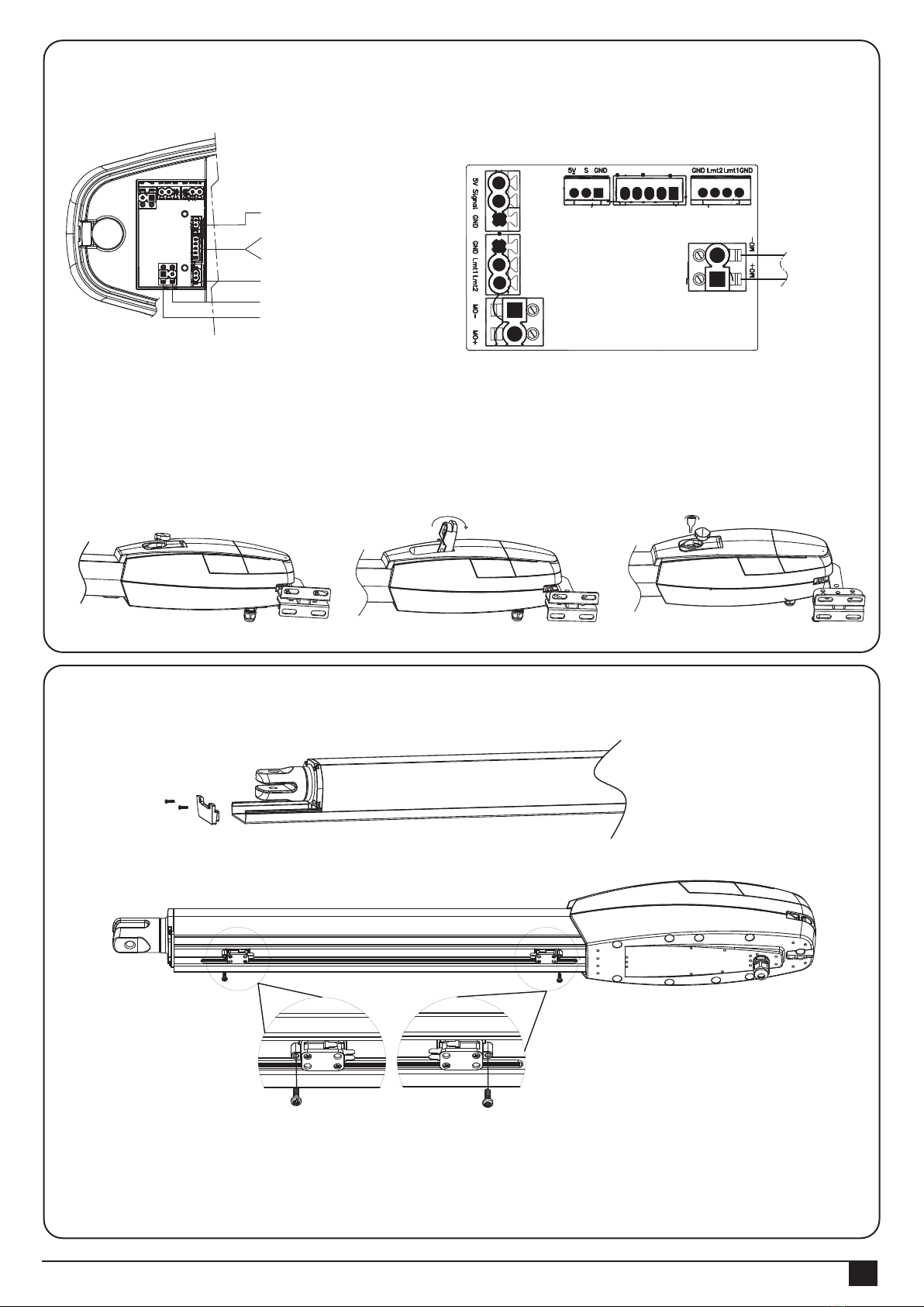
The basic wiring diagram is shown in Figure 2 .
No wiring cables for accessories are supplied with PW530.
2.4 Cable Connection
PW530 is required to connect two cores wire, which requires very low voltage and non-professionally trained
personnel is required in installation; however, the users are advised to read this installation manual carefully before
installation. After decided the position of all accessories, please starting from cable conduit arrangement
to prevent the cables from being broken or damaged
2.5 Power Connection
1. The installation of power supply cable to the control box should be carried out by a qualified professional electrician.
2. Please make sure to shut off the power before installation or maintenance.
Figure 2
2) Product Description and Applications
I
J
F
E
C
H
G
A
A
2.2 Tools need for Installation
Please make sure all tools and cables are ready and conform to the industrial safety standard before installation.

INSTRUCTIONS PW530
4
Check the following items before going for installation:
3.1 Preparation for Motor Installation
3. Installation
1). Make sure the weight and dimensions of gate conform to the operation range of PW530.
Don’t use PW530 if the gate specifications did not meet the requirements.
2). Make sure the gate structure conform to the criteria of automatic operation and force regulations.
3). Make sure there is no serious friction existing in the opening or closing travel of the gate leaves.
4). Make sure the gate is at horizontal level that the gate will not move aside at any position.
5). Make sure the gate can bear the impact of the motor torque when it is installed on any hole of the bracket which
the surface is sufficiently sturdy.
6). Make sure the photo sensors are installed on flat surfaces to ensure the two ends of receiving and transmitting
corresponded to each other.
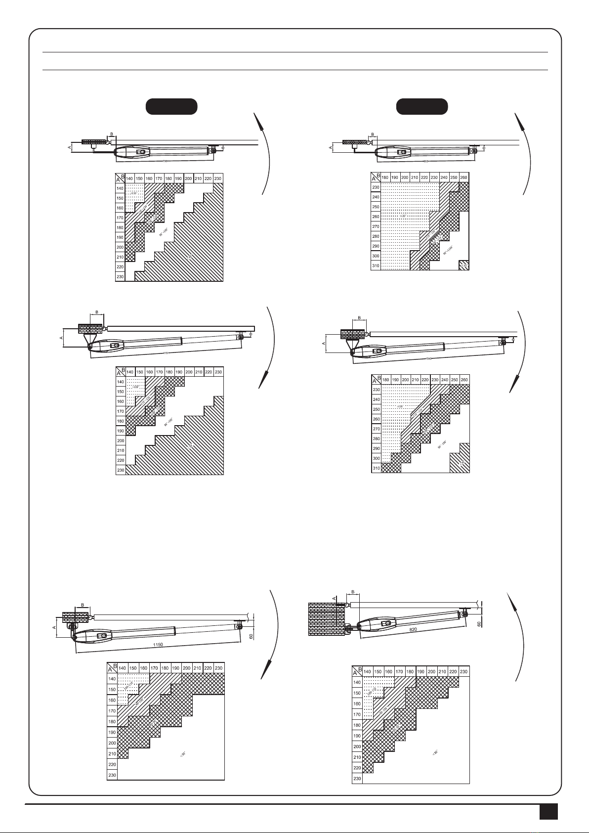
7). Check the dimensions of the motors as below.
PW530
PW530L
INSTRUCTIONS PW530 5
8). Make sure to leave enough space when the gate is opening.
9) Using the leaf-opening angle reference chart below
10). The value of “B” can be calculated from the value of “A” and the leaves opening angle. Ex. If “A”=160mm with
the leaves opening angle of 100 degrees, then the value of “B” is approximate 190mm.
**Please make sure “B” and “A” are similar or the same in value that the leaves can be operated smoothly,
also to reduce the burden of the motor.
PW530 PW530L
A. Without limit switches
B. With limit switches
INSTRUCTIONS PW530
6
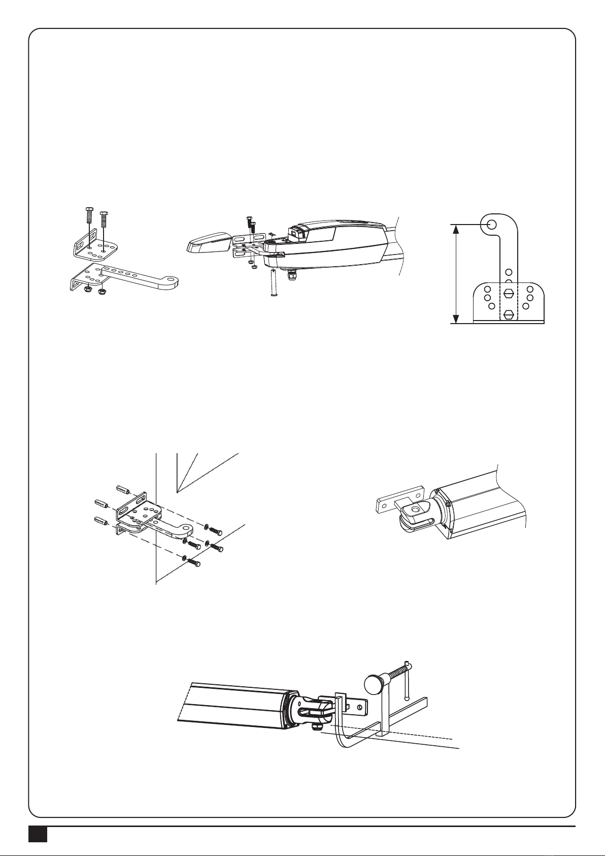
Figure 18
Figure 22
Figure 20
Figure 21
Figure 19
3.2 Installation of the motor
1. Choose the correct dimensions of the motors and position to be installed.
2. Check if the brackets mounting surface is smooth, vertical and rigid.
3. Arrange the cable conduit for power supply cable of the motors.
4. In order to obtain the optimal supporting from the rear plate, please assemble two post brackets and one rear metal
plate according to Figure 18.
5. Remove the back cover of the motor as shown in Figure 19
6. Place the door leaves at the closed position.
Figure 23
11. Clamp and fix the motor front plate on the door temporarily.
7. Refer to the distance of “B” in Figure 21, place the rear plate in the correct position on the mounting surface.
8. Place two post brackets on the surface to be installed and mark the drilling points, then drill minimum diameter
of 8mm holes by four on the mounting surface to be installed and fasten up the brackets with screws and washers.
9. Please make sure the front plate is completely installed horizontally.
139
INSTRUCTIONS PW530 7
Figure 25 Figure 26 Figure 27
Figure 24
14. Gear Motor Release
1) Open the rubber cover. See Figure 25
2) Lift the release part to the end. See Figure 26
3) Insert the key and turn clockwise to release. See Figure 27
Procedures:
1. Loosen the screws and slide the cover out.
2. Loosen the screws on the Limit Switches and adjust to the proper position.
3. Tight up the screws and put the cover back.
3.3 Limit switch adjustment
12. Lift up the motor and insert the screws into the front plate.
13. Connect the motor power cable as shown in Figure24.
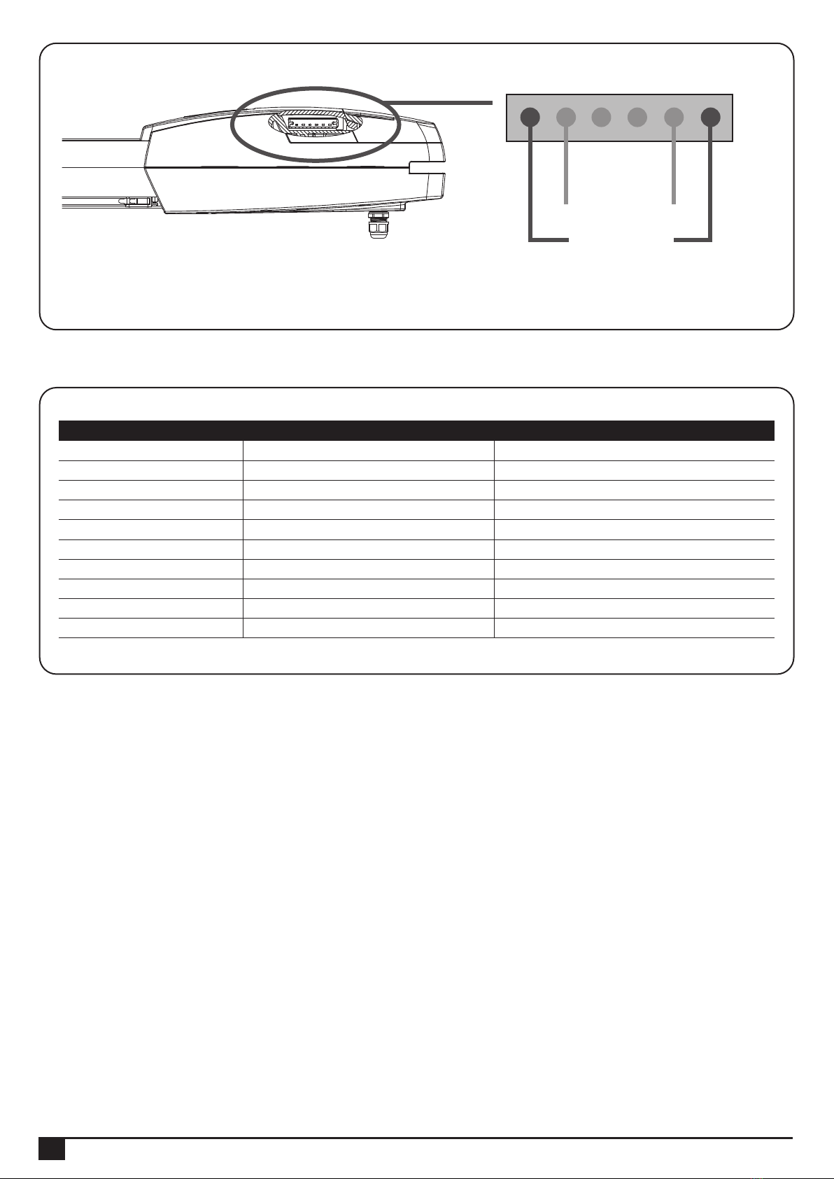
Hall Sensor
LED indicator (L)
LED indicator (R)
Limit Switch
White (+)
Yellow (-) Motor cable
Hall Sensor LED indicator Limit Switch
Motor cable
INSTRUCTIONS PW530
8
4) Technical Characteristics
4.1/4.2 PW530
Motor
Gear type
Nominal thrust
Power supply
Maximum operating current
Maximum gate weight
Maximum gate length
Duty cycle
Operating Temperature
Dimension
24Vdc motor with mechanical release
Worm gear
4500N
24Vdc
4.2A for maximum 10 seconds.
450 kg per leaf
3.5 meters
20%
-20℃~+50℃
846mm * 129mm * 127mm
24Vdc motor with mechanical release
Worm gear
5500N
24Vdc
6A for maximum 10 seconds.
550 kg per leaf
4 meters
20%
-20℃~+50℃
1041mm * 129mm * 127mm
350mm Stroke 540mm Stroke
1. During motor operation, the Blue LED indicator on the side will show.
A. When motor traveled to the both ends, the Red LED will show to indicate the door already open to the limit.
3.4 LED Indicators
Motor Indicator
Limit Indicator
Indice
Altri manuali Medva Apricancello


