Meinberg GPS167LCD-MP Manuale utente

Technical Information
Operating Instructions
FUNKUHREN
GPS167LCD-MP

Impressum
Werner Meinberg
Auf der Landwehr 22
D-31812 Bad Pyrmont
Phone: ++49 52 81 - 9309-0
Fax: ++49 52 81 - 9309-30
Internet: http://www.meinberg.de
Email: [email protected]
September 23, 2004

Table of Contents
Impressum ............................................................................................ 2
General Information............................................................................. 7
The Modular System GPS167LCD-MP .............................................. 9
GPS167 Features.................................................................................. 9
Time Zone and Daylight Saving................................................. 9
Pulse Outputs ............................................................................ 10
Time Capture Inputs ................................................................. 10
Asynchronous Serial Ports........................................................ 10
DCF77 Emulation..................................................................... 11
Installation.......................................................................................... 12
Mounting the Antenna .............................................................. 12
Assembly with CN-UB/E ......................................................... 13
Antenna Short-Circuit .............................................................. 14
Powering Up the System .......................................................... 14
The Front Panel Layout ..................................................................... 15
FAIL LED ................................................................................ 15
LOCK LED .............................................................................. 15
LC Display................................................................................ 15
MENU Key ............................................................................... 15
CLR/ACK Key ......................................................................... 15
NEXT Key................................................................................ 16
INC Key.................................................................................... 16
The Menus in Detail........................................................................... 16
Root Menu ................................................................................ 16
Menu RECEIVER POS. ........................................................... 17
Menu SV CONSTELLATION................................................. 17
Menu SV POSITION ............................................................... 18

Menu GOOD SVS 24HOURSS MIN/MAX ............................ 18
Menu USER CAPTURE .......................................................... 18
Menu SETUP............................................................................ 19
SETUP ENABLE OUTPUTS ........................................ 19
SETUP TIME ZONE...................................................... 20
SETUP DAYLIGHT SAV ON/OFF .............................. 20
SETUP SERIAL PORT PARM...................................... 22
SETUP SERIAL STRING TYPE................................... 22
SETUP SERIAL STRING MODE ................................. 23
SETUP INITIAL POSITION ......................................... 24
SETUP INITIAL TIME.................................................. 24
INIT USER PARMS ....................................................... 24
INIT GPS PARMS.......................................................... 25
FORCE BOOT MODE ................................................... 25
ANTENNA CABLE ....................................................... 26
Resetting Factory Defaults................................................................. 26
Firmware Updates .............................................................................. 27
Skilled/Service-Personnel only: Replacing the Lithium Battery ....... 27
Technical Specifications GPS167LCD-MP....................................... 28
Front/Rear Panel Connectors.................................................... 28
Rear View GPS167LCD-MP.................................................... 29
Pin Assignments of the SUB-D Connectors............................. 30
CE Label ................................................................................... 30
Technical Specifications GPS167 (OCXO-LQ) ................................ 31
Technical Specifications GPS167 Antenna.............................. 34
Time Strings ............................................................................. 35
Format of the Meinberg Standard Time String............... 35
Format of the GPS167 Capture String ............................ 36

Format of the SAT-Time String...................................... 37
Format of the Uni Erlangen String (NTP) ...................... 38
Format of the NMEA 0183 String (RMC)...................... 40
Format of the ABB SPA Time String ............................. 41
Format of the Computime Time String........................... 42
Signal Description GPS167 ...................................................... 44
Rear Connector Pin Assignments GPS167............................... 45
Technical Specifications Power Supply T-60B ................................. 46
Menu Quick Reference GPS167LCD-MP ......................................... 47


General Information
The satellite receiver clock GPS167 has been designed to provide extremly precise
time to its user. The clock has been developed for applications where conventional
radio controlled clocks can´t meet the growing requirements in precision. High
precision available 24 hours a day around the whole world is the main feature of the
new system which receives its information from the satellites of the Global Posi-
tioning System.
The Global Positioning System (GPS) is a satellite-based radio-positioning, naviga-
tion, and time-transfer system. It was installed by the United States Departement of
Defense and provides two levels of accuracy: The Standard Positioning Service (SPS)
and the Precise Positioning Service (PPS). While PPS is encrypted and only available
for authorized (military) users, SPS has been made available to the general public.
GPS is based on accurately measuring the propagation time of signals transmitted
from satellites to the user´s receiver. A nominal constellation of 21 satellites together
with several active spares in six orbital planes 20000 km over ground provides a
minimum of four satellites to be in view 24 hours a day at every point of the globe.
Four satellites need to be received simultaneously if both receiver position (x, y, z)
and receiver clock offset from GPS system time must be computed. All the satellites
are monitored by control stations which determine the exact orbit parameters as well
as the clock offset of the satellites´ on-board atomic clocks. These parameters are
uploaded to the satellites and become part of a navigation message which is retrans-
mitted by the satellites in order to pass that information to the user´s receiver.
The high precision orbit parameters of a satellite are called ephemeris parameters
whereas a reduced precision subset of the ephemeris parameters is called a satellite´s
almanac. While ephemeris parameters must be evaluated to compute the receiver´s
position and clock offset, almanac parameters are used to check which satellites are in
view from a given receiver position at a given time. Each satellite transmits its own set
of ephemeris parameters and almanac parameters of all existing satellites.
7

8
9
The Modular System GPS167LCD-MP
GPS167LCD-MP GPS-Receiver is a set of equipment composed of a satellite control-
led clock GPS167 (LQ-OCXO) together with a power supply unit Mean Well T-60B,
both installed in a metal desktop case MULTIPAC and ready to operate. The inter-
faces and input/output signals provided by GPS167 are accessible via connectors in
the rear and the front panel of the case. Details of the components are described below.
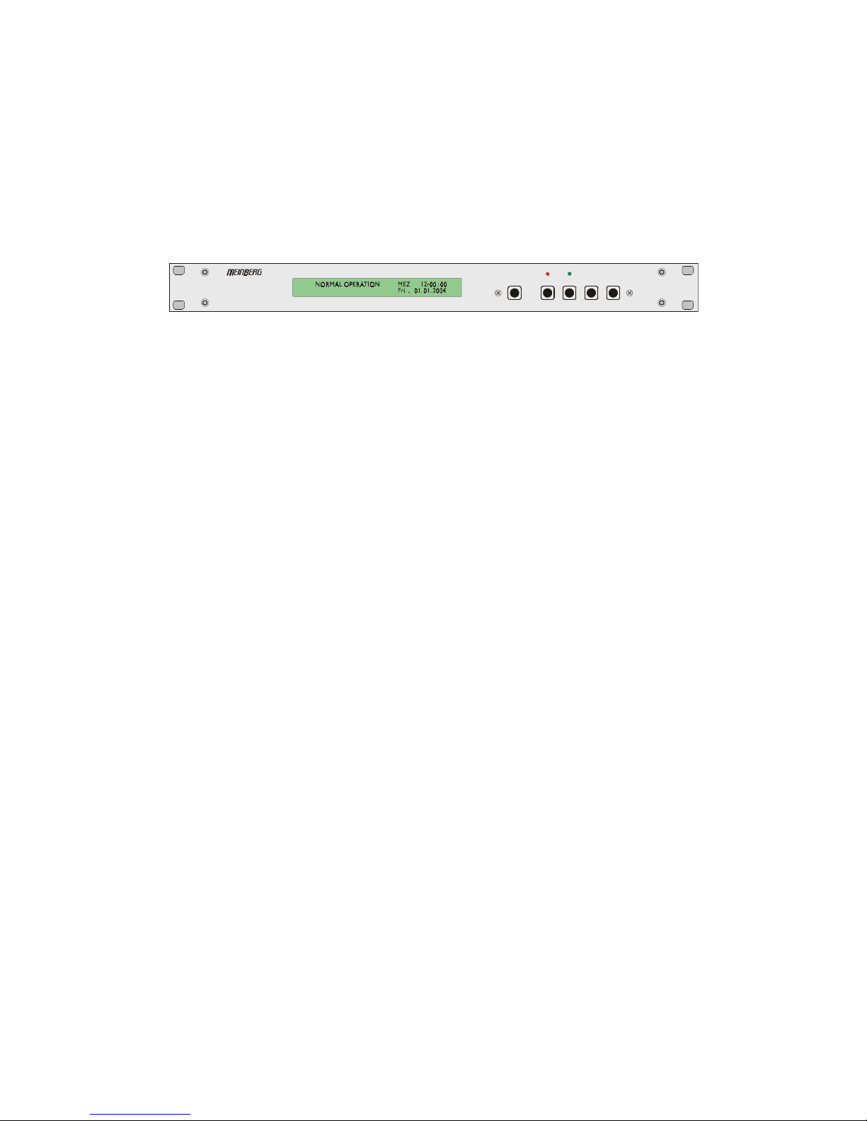
LOCK
CLR/ACK NEXT INC
FAIL
MENU
LIGHT
GPS167 LCDMP
satellite controlled
GPS167LCD-MP GPS-Receiver in desktop case MULTIPAC (front view)
GPS167 Features
The front panel integrates a 2 x 40 character LC display, two LED indicators and five
push buttons. The receiver is connected to the antenna/converter unit by a 50 ohm
coaxial cable (refer to "Mounting the Antenna"). Feeding the antenna/converter oc-
curs DC insulated via the antenna cable. Optional an antenna splitter for up to four
receivers connected to one antenna is available.
GPS167 is using the "Standard Positioning Service" SPS. The altitude with its
variation of ±180m is the most inaccurate component of the position. This inaccuracy
is caused by the operator (United States Departement of Defense) and not by the
GPS167, but it has no influence on the accuracy of the generated time. The navigation
message coming in from the satellites is decoded by GPS167´s microprocessor in
order to track the GPS system time. Compensation of the RF signal´s propagation
delay is done by automatical determination of the receiver´s position on the globe. A
correction value computed from the satellites´ navigation messages increases the
accuracy of the board´s oven controlled master oscillator (OCXO) and automatically
compensates the OCXO´s aging. The last recent value is restored from the battery
buffered memory at power-up.
Time Zone and Daylight Saving
GPS system time differs from the universal time scale UTC (Universal Time Coordi-
nated) by the number of leap seconds which have been inserted into the UTC time
scale after GPS has been initiated in 1980. The current number of leap seconds is part
of the navigation message supplied by the satellites, so GPS167´s internal real time is
based on UTC. Conversion to local time including handling of daylight saving year by
year can be done by the receiver´s microprocessor if the corresponding parameters are
set up by the user.

10
Pulse Outputs
The pulse generator of GPS167 generates pulses once per second (P_SEC) and once
per minute (P_MIN). Additionally, master frequencies of 10 MHz, 1 MHz and 100
kHz are derived from the OCXO. All the pulses are available with TTL level at the
rear connector.
In the default mode of operation, pulse outputs are disabled until the receiver has
synchronized after power-up. However, the system can be configured to enable those
outputs immediately after power-up. An additional TTL output (TIME_SYN) reflects
the state of synchronization. This output switches to TTL HIGH level when synchro-
nization has been achieved and returns to TTL LOW level if not a single satellite can
be received or the receiver is forced to another mode of operation by the user.
Time Capture Inputs
Two time capture inputs called User Capture 0 and 1 are provided at the rear connector
(CAP0 and CAP1) to measure asynchronous time events. A falling TTL slope at one
of these inputs lets the microprocessor save the current real time in its capture buffer.
From the buffer, capture events are transmitted via COM0 or COM1 and displayed on
LCD. The capture buffer can hold more than 500 events, so either a burst of events
with intervals down to less than 1.5 msec can be recorded or a continuous stream of
events at a lower rate depending on the transmission speed of COM0 or COM1 can be
measured. The format of the output string is ASCII, see the technical specifications at
the end of this document for details. If the capture buffer is full a message "** capture
buffer full" is transmitted, if the interval between two captures is too short the warning
"** capture overrun" is being sent.
Asynchronous Serial Ports
Two asynchronous serial interfaces are available to the user. In the default mode of
operation, the serial outputs are disabled until the receiver has synchronized after
power-up. However, the system can be configured to enable those outputs immediate-
ly after power-up. Transmission speeds, framings and mode of operation can be
configured separately using the setup menu. COM0 is compatible with other radio
remote clocks made by Meinberg. It sends Meinberg´s standard time string either once
per second, once per minute or on request with ASCII ´?´ only. The interfaces can also
be configured to transmit capture data either automatically when available or on
request. The format of the output strings is ASCII, see the technical specifications at
the end of this document for details. A separate document with programming instruc-
tions can be requested defining a binary data format which can be used to exchange
parameters with GPS167 via COM0.
Indice
Altri manuali Meinberg Orologio

Meinberg
Meinberg GPS161AHS Manuale utente

Meinberg
Meinberg GPS167TGP Manuale utente

Meinberg
Meinberg FUNKUHREN ANZ14_V3 Manuale utente

Meinberg
Meinberg PTP270PEX Manuale utente

Meinberg
Meinberg GPS169PCI Manuale utente

Meinberg
Meinberg GPS163DHS Manuale utente

Meinberg
Meinberg GPS164xHS Manuale utente

Meinberg
Meinberg GPS167SV Manuale utente

Meinberg
Meinberg TCR51USB Manuale utente

Meinberg
Meinberg GPS167 Manuale utente


