Meinberg TCR51USB Manuale utente

TCR51USB
Technical Information
Operating Instruction

Contact Information
Meinberg Funkuhren GmbH & Co. KG
Lange Wand 9
D-31812 Bad Pyrmont
Telefon: ++49 (0) 52 81 / 9309-0
Telefax: ++49 (0) 52 81 / 9309-30
Internet: http://www.meinberg.de
Email: [email protected]
Juli 12, 2011

Table of Contents
Contact Information .............................................................................. 2
Content of the USB stick ...................................................................... 4
Introduction .......................................................................................... 5
Description of IRIG-Codes................................................................... 5
IRIG-Standard format ........................................................................... 6
AFNOR-Standard format ..................................................................... 7
Features TCR51USB ........................................................................... 8
Functional description ................................................................. 9
USB Interface ..................................................................................... 10
Connectors and LEDs ............................................................... 10
Buffering ............................................................................................ 10
Putting into operation ................................................................ 11
Installing the TCR51USB ......................................................... 11
Power supply............................................................................. 11
Input signals .............................................................................. 11
Input impedance ................................................................................. 12
Photocoupler input .................................................................... 12
Configuration of TCR51USB ................................................... 12
Firmware Updates .............................................................................. 13
Technical specification TCR51USB .................................................. 13
CE Label ................................................................................... 14

4
Content of the USB stick
The USB stick contains a driver program that keeps the computer´s system time
synchronous to the board time. If the present delivered stick doesn’t include a driver
program for the operating system used, it can be downloaded from:
http://www.meinberg.de/english/sw/
On the USB stick there is a file called „readme.txt“, which helps installing the driver
correctly.

5
Introduction
The transmission of coded timing signals began to take on widespread importance in
the early 1950´s. Especially the US missile and space programs were the forces behind
the development of these time codes, which were used for the correlation of data. The
definition of time code formats was completely arbitrary and left to the individual ideas of
each design engineer. Hundreds of different time codes were formed, some of which
were standardized by the „Inter Range Instrumantation Group“ (IRIG) in the early 60´s.
Except these „IRIG Time Codes“ other formats, like NASA36, XR3 or 2137, are still
in use. The board TCR51USB however only decodes IRIG-A, IRIG-B or AFNOR
NFS 87-500 formats. The AFNOR code is a variant of the IRIG-B format. Within this
code the complete date is transmitted instead of the ‘Control Functions’ of the IRIG-
telegram.
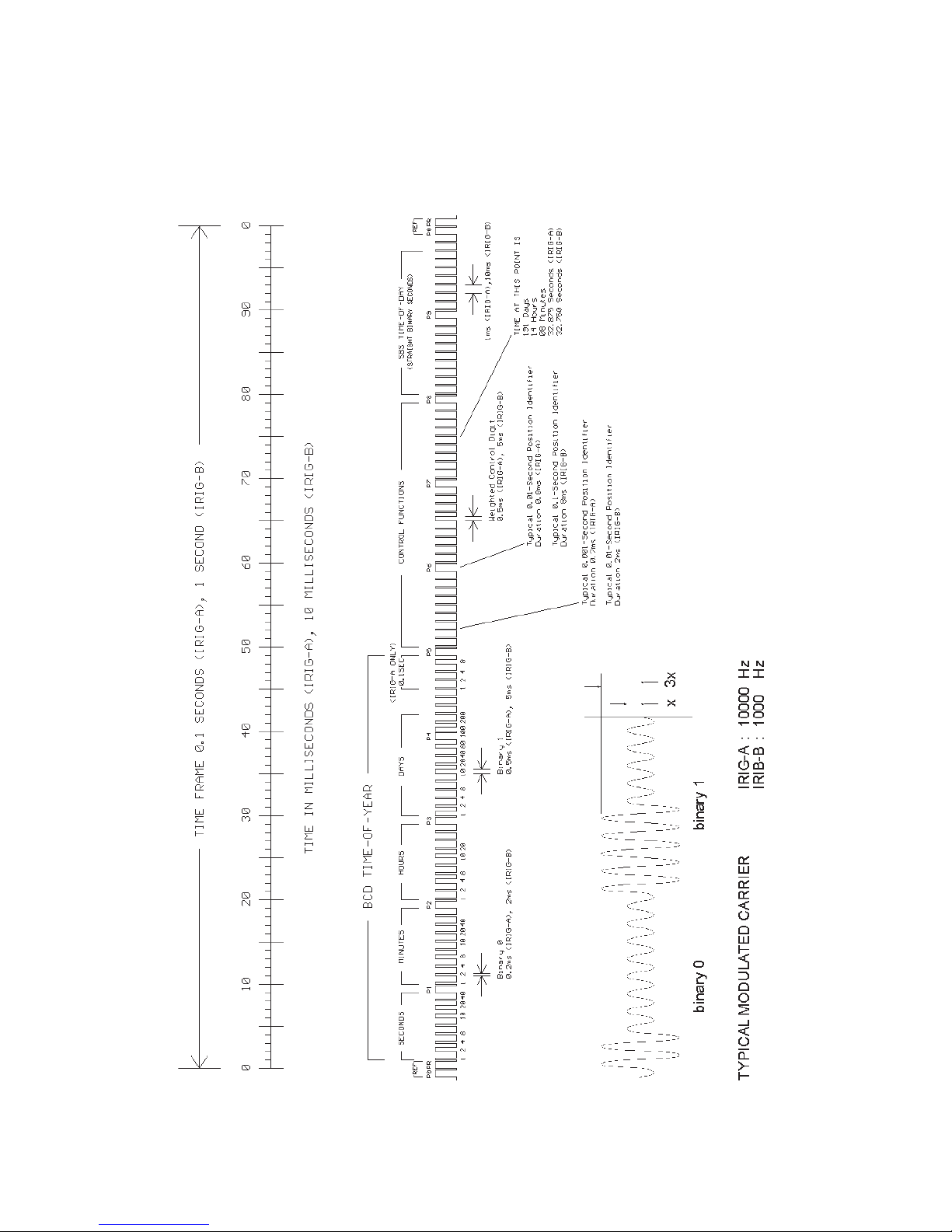
Description of IRIG-Codes
The specification of individual IRIG time code formats is defined in IRIG Standard 200-
98. They are described by an alphabetical character followed by a three-digit number
sequence. The following identification is taken from the IRIG Standard 200-98 (only the
codes relevant to TCR51USB are listed):
character bit rate designation A 1000 pps
B 100 pps
1st digit form designation 0 DC Level Shift
width coded
1 sine wave carrier
amplitude modulated
2nd digit carrier resolution 0 no carrier (DC Level Shift)
1 100 Hz, 10 msec resolution
2 1 kHz, 1 msec resolution
3 10 kHz, 100 µsec resolution
3rd digit coded expressions 0 BCD,CF,SBS
1 BCD,CF
2 BCD
3 BCD,SBS
BCD: time of year, BCD-coded
CF: Control-Functions (user defined)
SBS: seconds of day since midnight (binary)
6
IRIG-Standard format
7
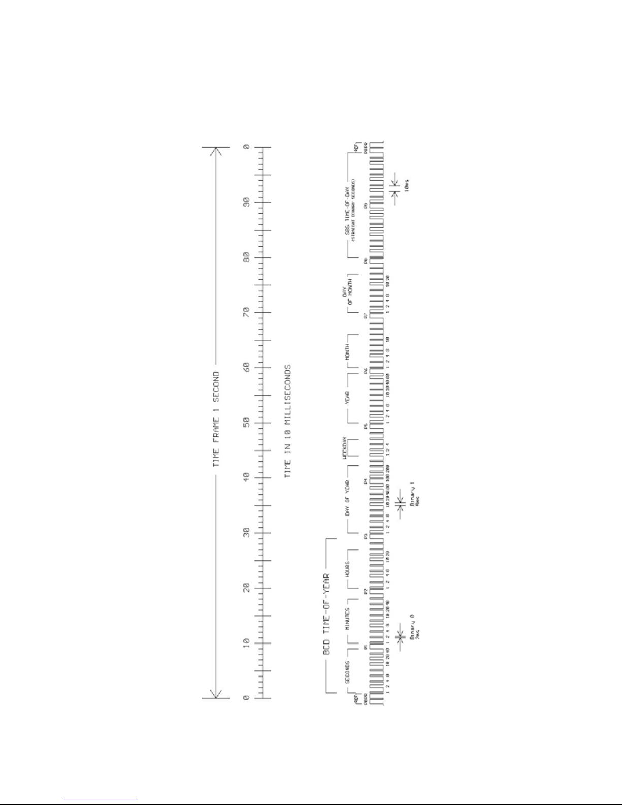
AFNOR-Standard format

8
Features TCR51USB
The TCR51USB was developed for computer systems with USB connection.
TCR51USB serves to receive and decode modulated (AM) and unmodulated (DC Level
Shift) IRIG and AFNOR time codes. AM-codes are transmitted by modulating the
amplitude of a sine wave carrier, unmodulated codes by variation of the width of pulses.
Automatic gain control within the receive circuit for modulated codes allows decoding
of IRIG signals with a carrier amplitude of 600 mVpp to 8 Vpp. The input stage is
electrically insulated and has an impedance of 50 Ω, it is accessible via the SMB-jack
connector in the housing of TCR51USB.
The unmodulated time codes must be connected to the second SMB jack connector.
An onboard photocoupler insulates the internal receive circuit.
Software running on the computer can read out information regarding date, time and
status of the IRIG receiver. Access to the board is made via writing to/reading from I/O
ports. It is possible but not necessarry to let the board generate periodic hardware
interrupts on the USB Bus.
The microprocessor system of TCR51USB is equiped with a Bootstrap-Loader and a
Flash-EPROM. These features enable updating of the onboard software.
9
Functional description
After the received IRIG code has passed a consistency check, the software clock and
the battery backed realtime clock of TCR51USB are synchronized to the external time
reference. If an error in the IRIG telegram is detected, the system clock of the board
switches to holdover mode. Drifting of the internal time base is limited to 1µsec/sec by
regulating the onboard quartz of TCR51USB. IRIG code includes day of year informa-
tion only. The complete date is kept in the battery backed realtime clock and the software
clock therefore. The received day of year is compared to this complete date once per
minute. If the board detects a difference between received and stored date information,
TCR51USB switches to holdover mode but still synchronizes the internal time base to
the received IRIG code.
The internal system clock is always set to the received IRIG time,
which might have a local offset to UTC. Only if TCR51USB is
configured with this offset, Meinberg driver software is able to set
the system time of the computer correctly.
IRIG telegrams don’t include announcers for the change of time
zone (daylight saving on/off) or for the insertion of a leap second.
Hence the clock will switch into freewheeling mode in case of such
event, and resynchronize afterwards.
The board TCR51USB decodes the following formats:
A133: 1000pps, amplitude modulated sine wave signal, 10 kHz carrier frequency
BCD time of year, SBS time of day
A132: 1000pps, amplitude modulated sine wave signal, 10 kHz carrier frequency
BCD time of year
A003: 1000pps, DC Level Shift pulse width coded, no carrier
BCD time of year, SBS time of day
A002: 1000pps, DC Level Shift pulse width coded, no carrier
BCD time of year
B123: 100pps, amplitude modulated sine wave signal, 1 kHz carrier frequency
BCD time of year, SBS time of day
B122: 100pps, amplitude modulated sine wave signal, 1 kHz carrier frequency
BCD time of year
B003: 100pps,DC Level Shift pulse width coded, no carrier
BCD time of year, SBS time of day
B002: 100pps, DC Level Shift pulse width coded, no carrier
BCD time of year
AFNORNFS87-500:100pps, amplitude modulated sine wave signal, 1 kHz carrier frequency
BCD time of year, complete date, SBS time of day
Additional codes are available on request
10
USB Interface
The TCR51USB contains a USB interface which is used for the communication and
parameterization of the device with the Monitorprogramm.
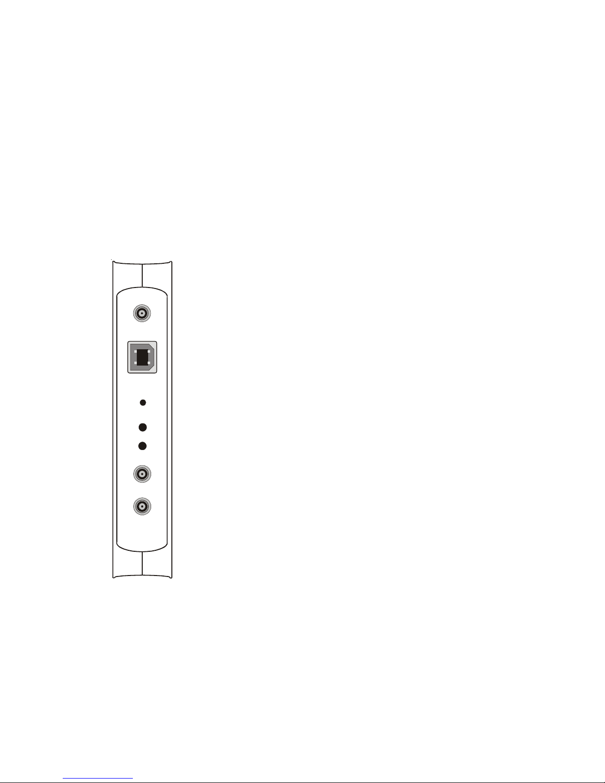
Connectors and LEDs
The housing of the TCR51USB contains the connectors for the Timecode (IRIG AM/
DC), two LED‘s, the key for the Bootstrap-Loader as soon as the the USB connector.
The LEDs signal the status of the IRIG receiver.
The upper, red LED is switched on whenever the
internal timing of TCR51USB is in holdover mode.
This state arise after power up and if an error in the
IRIG telegram is detected. This LED changes state
only at change of minute.
The green LED (Lock) is switched on as soon as
the internal timing of TCR51USB is synchronized
to the received IRIG code by a PLL (Phase Locked
Loop).
Pressing the hidden key BSL is required for acti-
vating the Bootstrap-Loader before updating the
firmware.
The USB connector is used for the
communication of the Device with the PC.
IRIG AM
IRIG DC
Lock
Holdover Mode
USB Connector
BSL
PPS (optional)
Altri manuali per TCR51USB
1
Indice


