SD1+
Telephone Numbers
The SD1+ can dial up to four different telephone
numbers. These numbers can be up to 24 digits long
and are programmed using the LCD display and
keypadontheunit.Thenumberscanbeforcedtotone
or pulse dial if required and a pause can also be
programmed. It is also possible for the SD1+ to dial a
pagerandsenda numericalmessage, thismessage is
programmed by the user (a digit is also sent after the
message that corresponds to the trigger input e.g. 1, 2
3 or 4 = Trigger A, B, C or D).
Recording Messages
The SD1+ has a built-in microphone so that phrases
can be recorded directly into the unit. The message
that is sent by the SD1+ consists of a common phrase
(0) which normally states your name & address,
followedbyphraseA,B,CorDwhichrelatetotheinputs
applied from the control panel. The SD1+ has up to 40
seconds of recording time which has to be shared by
all 5 phrases. It must be noted that if 10 seconds is
initially used by phrase 0 and you need to re-record
that phrase, 10 seconds must be used by the new
phrase 0.
Deleting Phrases and Numbers
Because the SD1+ has a Non Volatile Memory (NVM),
thephonenumbersandmessages cannotbedeleted
byremovingpowerfromtheunit.Thisoption,allowsyou
todeleteallphrasesorallphonenumbersasrequired.
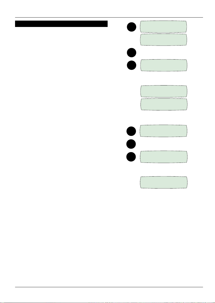
Playing Back Messages
Once the phrases have been recorded by the SD1+,
they can be played back through the on board
speakersothatyoucancheck therecordedmessage.
ItshouldbenotedthatwhenyouplaybackphrasesA,B
C or D, phrase 0 is always played first.
Sending a Test Call
Once the SD1+ has been programmed, each
message can be sent to a particular number to test
whether the unit is working correctly. When the unit is in
this test mode, everything on the phone line will be
heard through the speaker. The display will also give a
visualindicationofwhatishappeningduringthecall.
Three Way Calling
This is a service that is normally provided by British
Telecom,ifthis serviceisenabled,theSD1+willuseitto
prevent anyone trying to block the telephone line.
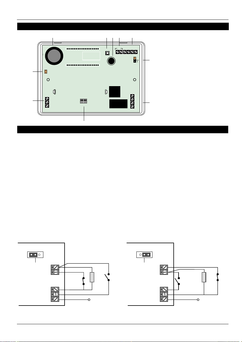
Installation Requirements
The SD1+ has been designed to be connected to an
intruder alarm control panel or similar. The control
panel must have an auxiliary power output of between
11.5Vand14V,andtheabilitytoprovideaminimumof
100mA.
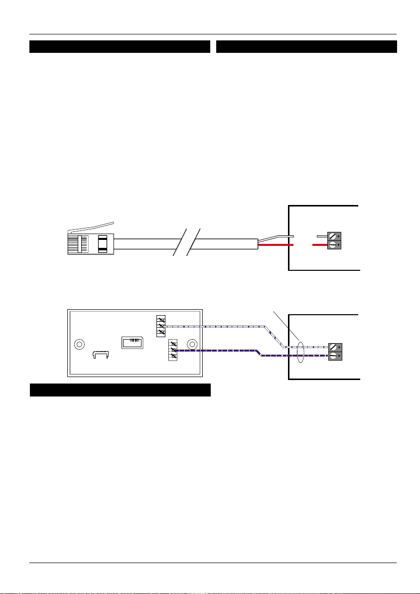
The unit is supplied with a 2 metre telephone lead
which will plug directly into any standard BT socket and
it is therefore recommended that the unit is sited as
near to a BT telephone socket as possible. If this it not
possible an approved BT extension lead may be
requiredortheunitcanbehardwiredtotheBT socket.
Mounting Instructions
1. Separate the cover from the base by using a
screwdriverto push two oftheretainingclips (top
or bottom) inwards from the base indents.
Remove cover assembly and store in a safe
place.
2. Holdthebaseinposition(keyholetothetop)and
markthethreesecuringholes.Removethebase
then drill and plug the holes.
3. Pass all cables into the base through the cable
entries and then secure the base to wall.
SD1+ 2of12 496540 Issue A