Merlin G815D Manuale utente

1
Instructions for installation & use
Toll free helpline
Please have your serial number and
model name available before calling.
Australia 1800 638 234
New Zealand 0800 653 667
United Kingdom 0800 073 0112
www.merlingo.com
G815D
remote control openers
security at your fingertips
swing gates
residential gate opener for

G815D May 05
2
Important safety instructions for
installation
WARNING Incorrect installation can lead to severe injury. Follow all installation
instructions. Merlin Garage Openers Limited does not accept responsibility for
damage or injury resulting from installing this opener.
Prepare the gate for safe automation
Before installing the drive remove or disable any equipment, such as locks, that is not
needed for powered operation.
Check that the gate is in good mechanical condition and that it opens and closes properly.
Do not use force sensitivity adjustments to compensate for a binding or sticking gate.
Excessive force may damage the gate.
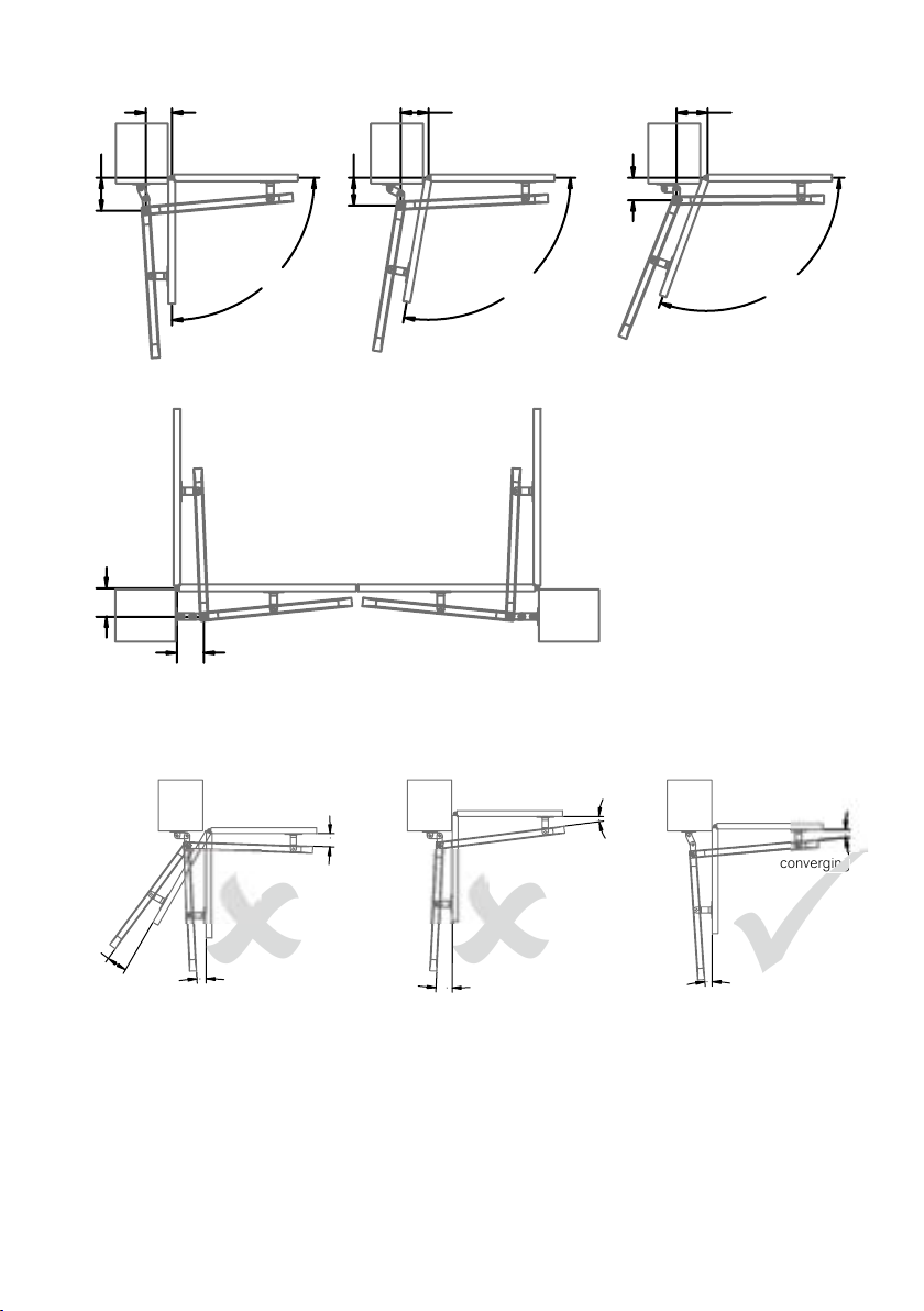
Avoid possible entrapment points
Ensure that entrapment between the driven part and the surrounding fixed parts due to the
movement of the driven part is avoided.
Gaps are considered safe as follows (IEC60335-2-103): finger gaps above 25 mm; foot
gaps above 50 mm; head gaps above 300 mm; and whole body gaps above 500 mm.
Add over-ride switch if wicket gate is present
If a wicket gate is present in one of the gate leaves, it must be fitted with a switch that
prevents the drive from operating when the wicket is open. (Connect a Normally Closed
switch to the STP and GND terminals of the controller board.)
Locate controls carefully
Install any fixed control, wired or wireless, within sight of the gate but away from moving
parts and at a height of more than 1.5 m.
Fit non-contact safety beams
Where they are not already explicitly required to comply with regulations, Merlin strongly
recommends fitting non-contact safety beam sensors.
Locate the entrapment warning sign correctly
After installing the gates, the included entrapment warning sign must be fitted within sight
of anyone that may stand in the path of the moving gate.
Inspect and test the installation
After installation, ensure that the mechanism is properly adjusted and that and the
protection system and manual release function correctly.
Educate the owner
Before passing controls to the owner, alert them to the potential dangers, and routine
checks they’re required to perform.
Complete the commissioning check sheet
The commissioning check sheet at the end of this manual must be completed, signed
by the installer and client, and kept on record by the installing company. It contains a
declaration that all safety related procedures have been complied with.

3
Important safety instructions for
use
WARNING It is important for the safety of persons to follow all the instructions for
use. Save these instructions.
Controls are not a toy
Do not allow children to play with fixed or remote controls.
Check the gate and drive for wear
Frequently examine the installation for imbalance and signs of wear or damage.
Check that the manual release functions correctly.
Do not use if repair or adjustment is necessary.
Test the safety system every month
Every month, test that the gates stop or reverse in response to an obstruction, and that
interrupting the beam of and photo-electric safety beam also causes the gate to stop or
reverse..
Do not use if repair or adjustment is necessary.
Disconnect power before maintenance
Always disconnect the power supply from the drive before cleaning or maintaining the
gate or drive. The drive or gate may operate unexpectedly due to other users with remote
controls, or due to automatic closing (if enabled).
Become familiar with the controls and manual release before use
Before using the gate and drive, locate the manual release and become familiar with its
operation. Note where the key is located, in the case of a power cut or any failure of the
drive or gate.
Contents
Manually opening the gate 4
Maintenance 4
Learning wireless controls 5
Deleting all wireless controls 5
Deleting selected wireless controls 5
Site requirements 6
Installation 9
Board setup 12
Make all connections 12
Set the application mode 15
Learn a remote control 15
Easy setup 16
Controls 17
Professional setup 21
Testing the gate operation 22
Troubleshooting 23
Specifications 24
Warranty 25
Service Centres 26
Quick setup guide 27
Commissioning check sheet 28

G815D May 05
4
Manually opening the gate
You can release the gate from the
opener. Insert the key into the lock
on the underside of the opener. Turn
the key and pull the lever down. The
gate will be released from the drive.
To reconnect the gate to the drive, it
may be necessary to move the gate
back to the same position as where
it was before unlocking.
Maintenance
In an area where ant or insect infestation is likely, regularly spray around the opener and
any electrical installation with insecticide. In normal conditions it is not expected that any
additional lubrication or service is required. Keep the path of the gate free from debris and
foliage.
The gate and its moving parts may sustain damage or wear, presenting additional load to
the opener. Frequently examine the installation for signs of wear or damage. Do not use if
repair or adjustment is needed as the gate may cause injury.
Each month check the sensitivity of your gate while it is closing and opening. Arrange
for an Authorised Installer to adjust if necessary since an incorrect adjustment may be
hazardous.
Each month check that any non-contact beam sensors function correctly by obstructing
them while the gate is moving. The gate should stop, or reverse. Ensure the beams are
clear of any obstructions or dirt and ensure they are aligned towards each other.
Insert key, turn
and pull the
lever down to
release the drive.

5
Learning wireless controls
1. Press P2/RADIO until the red LED is lit.
2. If the wireless remote controls are required to only operate Pedestrian Access
mode, install the CH-RADIO jumper over its pins. If the wireless remote controls
are for full access, remove the CH-RADIO jumper.
3. Press the desired button for 3 seconds once on each wireless control that is
required to operate the gate.
NOTE The red LED will blink during learning. The controller is ready for another wireless
control when the red LED is steadily lit.
4. Press P2/RADIO to exit learning mode.
NOTE The learning procedure will time out after 10 seconds of no activity.
Deleting all wireless controls
1. Press and hold the P2/RADIO button until the red LED blinks rapidly.
2. Release the P2/RADIO button.
3. Within 6 seconds, press the P2/RADIO button again to confirm.
Deletion is indicated by the red LED blinking faster.
Deleting selected wireless
controls
The optional accessory GT/SYSTEM hand-held controller is required. Contact Merlin for
details.

G815D May 05
6
Site requirements
Check that the temperature range marked on the drive is suitable for the location. Do not
install the drive where ambient temperatures will exceed the ratings.
Gate
This opener is designed for residential swing gates
up to 2 metres wide and less than 140 kg.
Using a spring balance at a point approximately 1
metre from the hinge, check that less than 8 kg
force (80 N) is required to manually move the gate
through its full range of movement, with the gate
disconnected from the drive.
The gate should operate smoothly, opening and
closing without sticking. Hinges should not have
excessive play or friction. Check the mounting
points and hinges for strength and stiffness.
Reinforce if necessary.
Gate posts
There should not be any visible flexing of the mounting points under load.
Level and square the gate
The gate hinge pivot points should be perfectly parallel to a plumb line. When closed, the
gate leaves should line up evenly and not bind against each other. The leaves should not
be damaged or bent.
Gate stops
It is recommended that any of the following are used:
• Overlapping gate leaves
• A tag on one gate
• Gate-stops at the limit of each leaf’s travel
Power supply
Mains powered
If the opener is to be mains-powered, then the 3-pin power plug should be shielded from
the effects of weather. The product is tested as a unit for electrical safety compliance
and if the plug is cut off for hard-wiring, then the electrical safety of the unit becomes the
responsibility of the installing electrician. An isolating switch is recommended, but all mains
wiring should be in accordance with local regulations.
Solar Powered
Contact Merlin for the correct battery and solar panel. The size of these depends on: the
duty cycle of the gates; the hours of sunlight; and the number and type of accessories
fitted.
maximum
8 kg force
1 metre

7
Battery powered with trickle charging
Due to the high cost of long runs of heavy cable, it may be more economic in some
installations to operate the gates from a larger battery, which is charged from a remotely
located trickle charger.
For example, a 16V ac 500 mA plug pack can be located at the house, with appropriate
wiring to the gate, controller, and battery some distance away. Due to varying gate loads
and duty cycles for each installation, this is a guide only.
Wiring
All wiring must be arranged to prevent water entering the controller enclosure.
Do not wire mains voltages and low voltage control wires in the same conduit.
Low voltage cable sizes
Voltage will drop along low voltage cables over long distances. It is recommended to use
cable with conductors of the following minimum cross sectional areas. The table lists
lengths for twin-core cable, from the supply to the load.
For an optional solar panel, consider the total length from the panel to the controller board,
through to the battery. Follow the table for minimum recommended conductor sizes for
given lengths for each power option.
Cable length From separate transformer/
solar panel to 12 V battery
(for max 2% volt drop)
From controller to each
motor 12 V @ 4 A max
(for max 5% volt drop)
3 m 1.0 mm21.5 mm2
5 m 1.0 mm22.5 mm2
10 m 1.0 mm24.0 mm2
15 m 1.0 mm26.0 mm2
20 m 1.0 mm210 mm2
25 m 1.5 mm210 mm2
30 m 1,5 mm216 mm2

G815D May 05
8
Master and slave operators
The Master operator has the controller board, transformer and optional back-up battery
inside it. Locate it on the side of the gate nearer to the power supply. The Slave operator
connects to the master by a two-core conductor carrying 12V.
1 Right hand opener (shown as master, but depends on site)
2 Left hand opener (shown as slave, but depends on site)
3 Receiving IR sensor (4-wire)
4 Transmitting IR sensor (2-wire)
5 Push-button (must be rated suitably for the weather conditions)
6 Keyed switch (must be rated suitably for the weather conditions)
7 Keypad (Merlin M840, wireless, optionally with wired power supply)
8 Solenoid lock or latch (avail. for horizontal or vertical applications)
NOTE The Merlin M122 wired and M128 wireless pushbuttons are not waterproof, and
are only rated for interior use. The Merlin KWF1 keyed switch is not intended for use fully
exposed to weather in gate installations. Merlin does not warranty any items used outside
their published ratings or intended use. It is also possible to locate the controller in an
enclosure and use two slave units. Contact Merlin for details.
4
5
2 1
8
7
3
6
230-240 V ac
50/60 Hz 100W max

9
Installation
Mounting brackets to the gate posts
There should not be any visible flexing of the mounting points under load.
To spread the load, all mounting holes should be used.
Use fasteners of at least 8 mm diameter x 75 mm length.
Height
Mount the centre line of the bracket either 10 or 5 mm higher than the centre line of the
gate bracket, depending on whether two or three pieces of post bracket are used. This is
to maintain a level actuator.
If the conditions are very dusty, for example around an unsealed driveway, do not mount
the actuators lower than 400 mm above the ground. This is to reduce the likelihood of dust
entering the screw mechanism.
Position relative to gate pivot
Refer to the diagram below for the typical co-ordinates of A and B.
Some guidelines for an easy installation are:
A + B < 340 for up to 90 degrees opening
A + B < 320 for up to 100 degrees opening
A + B < 310 for up to 110 degrees opening
Increase A for a slower but firmer stop open
Increase B for a slower but firmer stop closed
Optimum dimensions are:
opening angle A B P(max)
90º 190 150 160
100º 160 160 130
110º 130 180 100
Gate pivot offset from mounting face
The dimension P on the diagram must be:
less than 160 mm for 90 degrees of opening angle;
less than 130 mm for 100 degrees; and
less than 100 mm for 110 degrees.
Using two piece post bracket Using three piece post bracket
10
5
A
B
P

G815D May 05
10
Typical installations: in-swinging gates
Typical installation: out-swinging gate
IMPORTANT For all installations the angle between the drive arm and the gate should
always be convergent. If at any position the arm and gate are divergent, there will be
excessive stress placed on the gate components.
150
90º
100º
110º
160 180
130
160
190
155
165
converging
diverging
diverging
diverging
converging converging
converging
arm and gate converge at
one position, but diverge
at another, so installation
angles are not acceptable
arm and gate converging at
all positions so installation
angles are acceptable
arm and gate converge at
one position, but diverge at
others so installation angles
are not acceptable
converging
converging
diverging
diverging
WRONG! RIGHTWRONG!
Indice
Altri manuali Merlin Apricancello

Merlin
Merlin G930 Manuale utente

Merlin
Merlin G740A Manuale utente

Merlin
Merlin G950 Manuale utente

Merlin
Merlin G715D Manuale utente

Merlin
Merlin XLR8 MGS524 Manuale utente

Merlin
Merlin G703 Manuale utente

Merlin
Merlin G940 Manuale utente

Merlin
Merlin Swing L 300 MGLSK Manuale utente

Merlin
Merlin G915D Manuale utente

Merlin
Merlin Swing A 200 Manuale utente

Merlin
Merlin Slide 600 Manuale utente

Merlin
Merlin MGL400-24 Manuale utente

Merlin
Merlin G900 Manuale utente

Merlin
Merlin Swing A 200 Manuale utente

Merlin
Merlin Swing L300 Manuale utente

Merlin
Merlin prolift 430R Manuale utente

Merlin
Merlin G950 Manuale utente

Merlin
Merlin G950 Manuale utente

Merlin
Merlin G930 Manuale utente

Merlin
Merlin Slide 600 Manuale utente


