Met One Instruments 83529 Guida utente

Docking Station Set Up Manual 83529-9800 Rev A Page 2

Docking Station Set Up Manual 83529-9800 Rev A Page 3
Copyright Notice
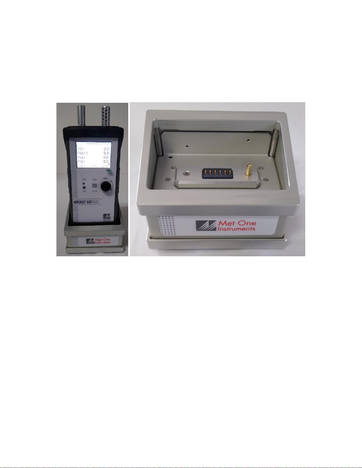
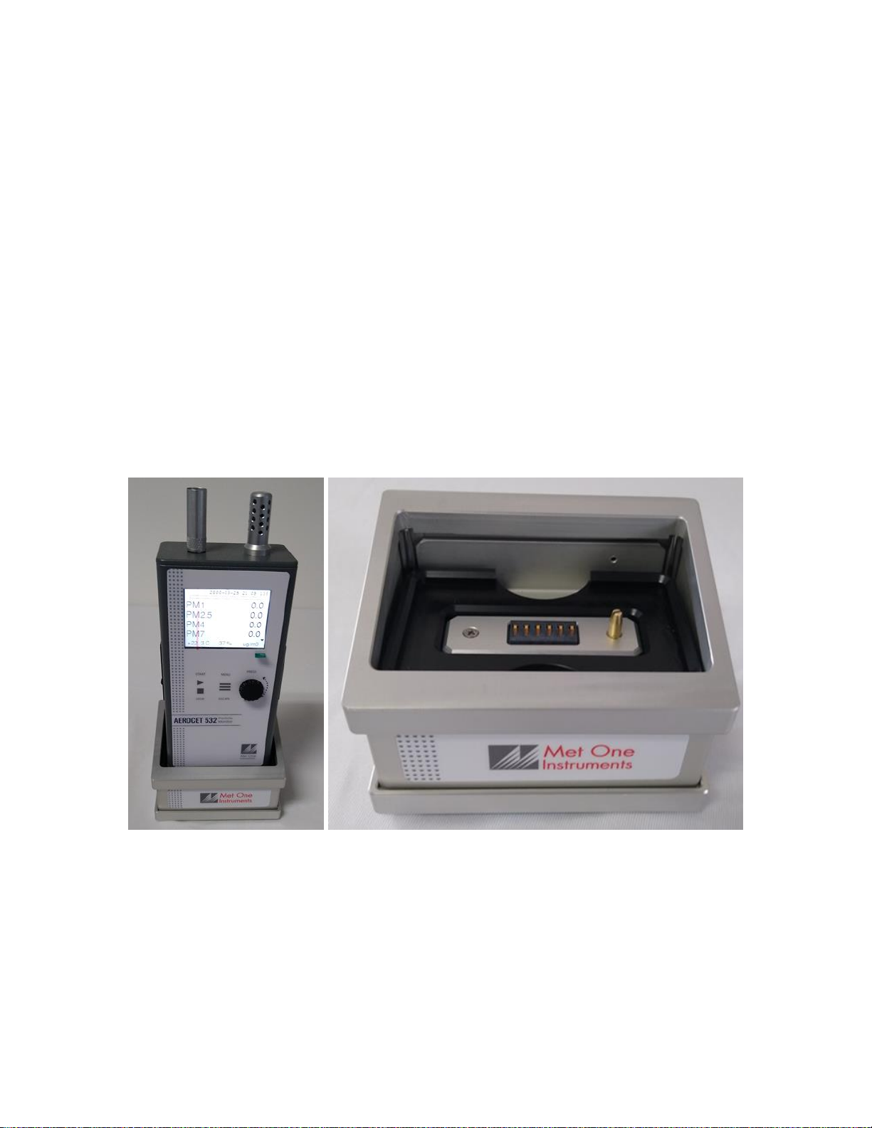
83529 Docking Station Set Up Manual
© Copyright 2021 Met One Instruments, Inc. All Rights Reserved Worldwide. No part of
this publication may be reproduced, transmitted, transcribed, stored in a retrieval
system, or translated into any other language in any form by any means without the
express written permission of Met One Instruments, Inc.
NOTE: This equipment has been tested and found to comply with the limits for a Class
A digital device, pursuant to part 15 of the FCC Rules.
Technical Support
This manual is structured by customer feedback to provide the required information for
setup, operation, testing, maintaining, and troubleshooting the 83529 Docking Station.
Should you still require support after consulting your printed documentation, we
encourage you to contact one of our expert Technical Service representatives during
normal business hours of 7:00 a.m. to 4:00 p.m. Pacific Time, Monday through Friday.
In addition, technical information and service bulletins are often posted on our website.
Please contact us and obtain a Return Authorization (RA) number before sending any
equipment back to the factory. This allows us to track and schedule service work and to
expedite customer service. Please have the instrument serial number available when
contacting the manufacturer.
Contact
Information:
Tel: + 541 471 7111
Fax: + 541 471 7115
Web: www.metone.com
Email: service@metone.com
Address:
Met One Instruments, Inc.
1600 NW Washington Blvd
Grants Pass, Oregon 97526
U.S.A.

Docking Station Set Up Manual 83529-9800 Rev A Page 4
Table of Contents
1. Introduction........................................................................................................... 5
2. Setup...................................................................................................................... 5
2.1. Unpacking..................................................................................................................................5
2.2. Layout........................................................................................................................................6
2.3. Power Up...................................................................................................................................7
3. Connecting a Device............................................................................................. 7
4. Communication Options and Setup .................................................................... 8
4.1. RS485 Communication..............................................................................................................8
4.2. WiFi Setup and Configuration....................................................................................................9
4.3. Ethernet Port Setup and Configuration ...................................................................................11
4.3.1. Setting the Static IP Address of the Docking Station........................................................11
4.3.2. Web Page Configuration...................................................................................................12
4.3.3. Setting up a Virtual COM Port...........................................................................................15
4.3.3.1. Installing the Virtual Serial Port Drivers:...................................................................................15
4.3.3.2. Configuring the Virtual Com Port for the Docking Station .......................................................16
5. Troubleshooting.................................................................................................. 20
6. Specifications...................................................................................................... 20

Docking Station Set Up Manual 83529-9800 Rev A Page 5
1. Introduction
The 83529 Docking Station is a power and communication accessory for select Met
One Instruments, Inc. handheld devices. It is able to charge the equipment battery and
also provides RS-485, Ethernet, and WiFi communication options.
Figure 1 - 83529 Docking Station with handheld device (left) and by itself (right)
2. Setup
The following sections cover unpacking, layout, and powering the equipment.
2.1. Unpacking
Unpack and inspect the contents of the shipping container. Contact the supplier if any
items are missing. Any damages incurred during shipping are the responsibility of the
carrier. If any damage to the shipment is noticed before unpacking, a claim must be filed
with the commercial carrier immediately. You should follow any special unpacking
instructions provided by the carrier as you then carefully remove all items from the
containers and inspect each component. It is recommended to document and
photograph all damaged packages and items before, during, and after unpacking them.
Contact Met One Instruments, Inc. (see the Technical Support section at the beginning
of this manual) to arrange for any replacement items needed. The Docking Station
comes with a bootless adapter and RS-485 terminal block plug.

Docking Station Set Up Manual 83529-9800 Rev A Page 6
2.2. Layout
The following figure shows the layout of the Docking Station and provides a description
of each of the components.
Figure 2 - Docking Station Layout
Component
Description
Battery Contact
Connects to a handheld device to charge the battery of the device. This
also works as a communication link between the station and connected
device.
Alignment Pin
Properly aligns a connected device in the proper orientation over the
battery contact.
RS485 Terminal Block Plug
Connects external communication wires to the RS485 input.
Bootless Adapter
Positions a device without a rubber boot in the docking station.
Power Supply Jack
Input for the 8.4V 1.3A power supply.
WiFi/Ethernet Switch
Selects either Ethernet or WiFi to be used. Slide switch to the right for
WiFi. Slide switch to the left for Ethernet.
Ethernet Port
Ethernet CAT5 cable connection.
RS485 Input
Connection for RS485 terminal block plug.
RS485 Terminal
Block Plug
Bootless Adapter
Power Supply
Jack
WiFi/Ethernet
Switch
Ethernet Port
RS485 Input
Battery Contact
Alignment Pin

Docking Station Set Up Manual 83529-9800 Rev A Page 7
2.3. Power Up
The Docking Station must be plugged in to work. A power supply is not included with
the docking station. The Docking Station is powered by the same 8.4V 1.3A power
supply shipped with the Met One Instrument, Inc. handheld device it will be used with.
This power supply must be used to provide the correct power to the unit. Do not
attempt to connect any other charger or adapter to this device. Doing so may result in
equipment damage.
3. Connecting a Device
The Docking Station is designed to charge the battery of select Met One Instruments,
Inc. handheld devices. The front of the device must face forward. An alignment pin is
positioned on the contact plate. This pin fits into a hole at the base of the handheld unit.
This is used to prevent damage to the docking station or handheld unit by stopping a
device from being placed on the docking station backwards.
Each device will fit securely onto the Docking Station when encased in its rubber boot.
If the rubber boot is not used, an 83584 bootless adapter is placed in the base of the
docking station to hold the device.
Figure 3 - Docking Station with device without rubber boot (left) and showing bootless
adapter in Docking Station (right)

Docking Station Set Up Manual 83529-9800 Rev A Page 8
4. Communication Options and Setup
The 83529 Docking Station provides RS485, WiFi, and Ethernet communication
options. The following sections describe each option in more detail.
4.1. RS485 Communication
The unit can operate in a Multi-Drop RS485 network using the RS485 connection on the
back of the Docking Station. The network address is the same as the Network ID of the
handheld device. It is important that no two units have the same Network ID set in the
same network. Figure 4 shows the RS485 connector both with and without the terminal
block plug installed. Note that the pin assignments are easier to read with the block
removed. Figure 5 shows a RS485 network wiring diagram.
Figure 4 - RS-485 connector
Figure 5 - RS485 Network

Docking Station Set Up Manual 83529-9800 Rev A Page 9
4.2. WiFi Setup and Configuration
The WiFi on the Docking Station will need to be connected to the local network where it
is used. This section covers the initial setup and configuration of the WiFi. Valid
credentials for a WiFi network in range and either a computer or smartphone that can
connect to that network must be used to configure the Docking Station.
1. Move the WiFi/Ethernet switch on the rear of the Docking Station to WiFi.
2. After powering on the Docking Station, the WiFi interface will generate a local
network that allows the user to connect to the Docking Station and configure the
connection.
3. On a WiFi enabled computer or smartphone search for an open WiFi network
that starts with “ESP_” and connect to the network.
4. On the connected device open a web browser and go to IP address 192.168.4.1
Figure 6 - Web browser with IP address
5. Navigate to the WiFi Station tab and click “Switch to STA+AP Mode” so that the
Docking Station can scan for networks in the area.
Figure 7 WiFi Station tab

Docking Station Set Up Manual 83529-9800 Rev A Page 10
6. Choose a WiFi network, enter the password, and click connect.
Figure 8 - WiFi Station Configuration
7. After the dock has connected to the network it will show the internal IP address it
was assigned from the network. Click the IP address to automatically navigate to
the new IP address. The dock will now automatically shut off its hosted network.
Figure 9 - WiFi Station Configuration
Indice


