Metrix HI-913 Manuale utente
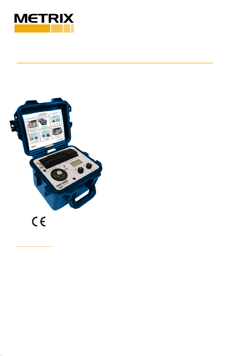
HI-913 HARDY SHAKER
Installaon Manual
DOC# 100929 • REV D (Jan 2018)
1. OVERVIEW
The Metrix Model HI-913 Portable Shaker
Table provides a eld-tested method
for on-the-spot dynamic vericaon of
accelerometers, velocity pickups and non-
contact displacement transducers. Oponal
mounng xtures and hardware needed to
connect transducers to the HI-913 mounng
plaorm are available upon request. A closed-
loop control algorithm provides enhanced
stability and accuracy of frequency and
amplitude levels.
The HI-913 incorporates a built-in sine wave
oscillator, power amplier, electrodynamic
shaker, NIST-traceable reference
accelerometer and digital display. The HI-913
is completely self-contained and operates on
baery or AC power.
The built-in reference accelerometer
is aached permanently to the shaker
armature, maximizing the accuracy between
the reference accelerometer and the test
transducer. The HI-913 is designed to provide
long-term reliable performance over the
frequency range of 7 Hz to 10 kHz. The HI-
913 can be used for a variety of applicaons
that include:
•Vericaon and calibraon of vibraon
transducers and related test systems
•Vericaon of connector and cabling
integrity
•Conrm machine vibraon alarm trip points
are set properly and ensure end-to-end
funconality of vibraon monitoring systems
Notes
•Loads of up to 800 grams (28.3 ounces) can
be mounted directly to the HI-913 mounng
plaorm. Larger loads may be applied to the
plaorm, however, if prolonged tesng of a
heavy load is planned, we recommend using
an external transducer suspension system.
Under these condions the vibraon wave-
form should be viewed on the oscilloscope
to aid in posioning the test transducer and
plaorm to reduce distoron that can occur
with very heavy weights.
Doc# 100929 • HI-913-Shaker • January 2018 - RevD Page 2 of 21
•The HI-913 should always be operated on a stable, at surface.
•The HI-913 is designed for eld test applicaons but care must be taken to maintain the
integrity of the mounng plaorm assembly.
•Hearing protecon recommended when operang the HI-913 for an extended amount of
me.
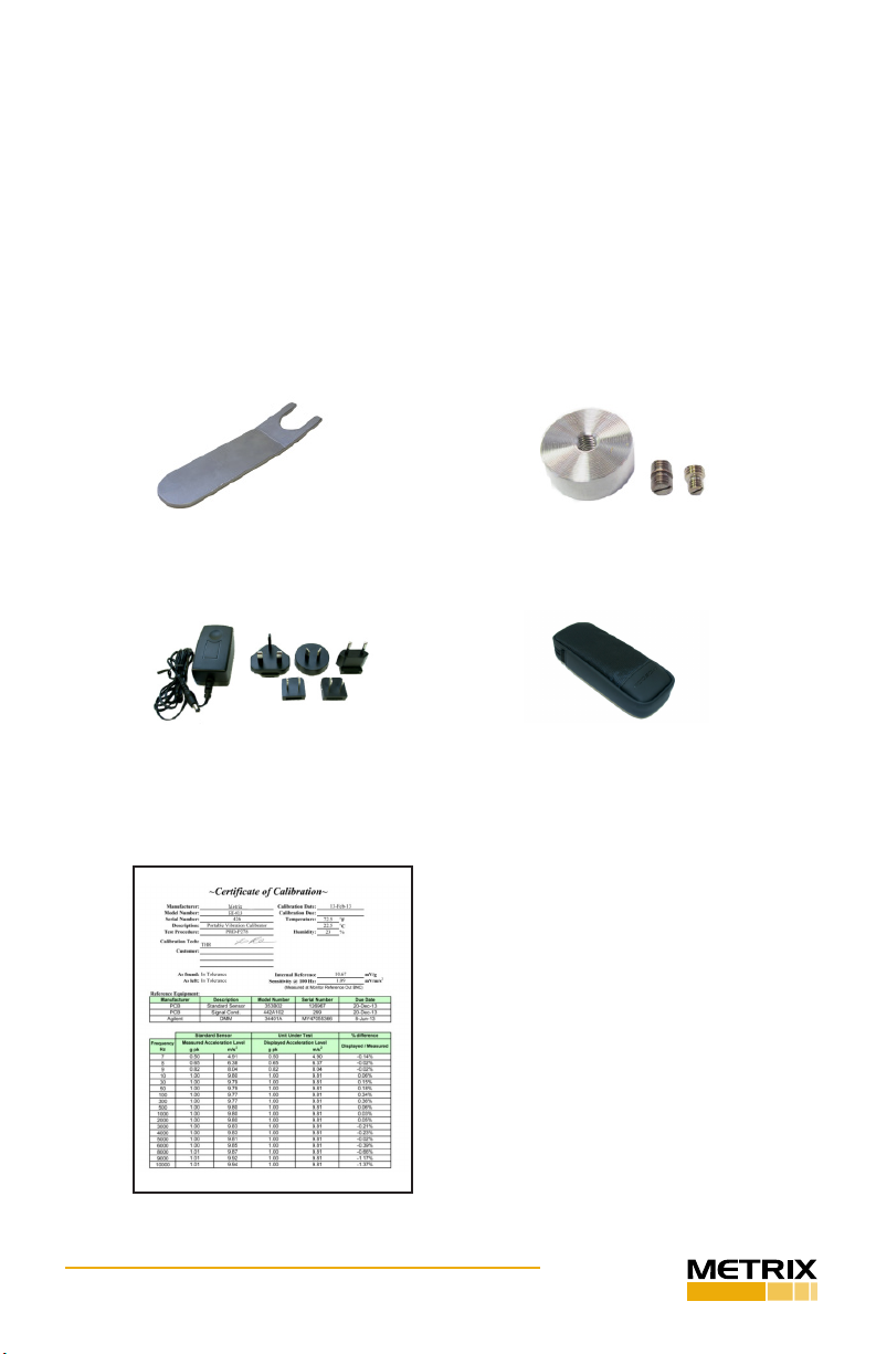
Accessories
Accessories pictured below are included with each HI-913 Portable Shaker Table.
Mounng Wrench 1-Mounng Pad
2-1/4-28 to 1/4-28 Adapter
3-10-32 to 1/4-28 Adapter
Power Supply and Plug Adaptors Acessory Pouch
A Cercate of Calibraon is also included
with every new unit. Metrix recommends
annual recalibraon of the HI-913 unit. The
factory service code for the recalibraon is
HI-913 CAL01.

Doc# 100929 • HI-913-Shaker • January 2018 - RevD Page 3 of 21
2. BASIC OPERATION
Test Set-Up
1. Mount your sensor to the HI-913 mounng plaorm.
• The HI-913 sensor mounng plaorm is threaded for a ¼-28 stud.
Select an appropriate adaptor for mounng the sensor.
• While ghtening the sensor, secure the HI-913 mounng plaorm
with the supplied wrench to prevent damage to the shaker from
torque.
2. Connect sensor signal condioner and readout device as necessary. Make sure
that connecons are secure.
3. Power the unit ON by pressing and holding the FREQUENCY dial for 3 seconds.
NOTE: It is good pracce to perform calibraons on baery power. Disconnecng
from line power ensures a power surge will not cause the calibrator to power down
during test. If excess current is detected during use, the portable calibrator shuts
down to prevent damage.
Seng the Frequency and Amplitude Units
1. Select the correct Frequency Units for your test by pressing the FREQUENCY dial
to enter into the CALIBRATION OPTIONS menu:
• Use the FREQUENCY dial to highlight TEST SETTINGS then press.
• Within the Test Sengs Menu rotate the FREQUENCY dial to highlight
FREQUENCY UNIT then press to toggle between Hertz and CPM.
2. Select the correct Amplitude Units for your test by pressing and releasing the
AMPLITUDE dial. The following opons are available:
Acceleraon Velocity Displacement
g’s pk
g’s RMS
m/s2 pk
m/s2 RMS
in/s pk
in/s RMS
mm/s pk
mm/s RMS
mils p-p
µm p-p
3. Select the desired vibraon amplitude and frequency for tesng by turning the
AMPLITUDE and FREQUENCY dials clockwise to increase or counter clockwise to
decrease the seng.
•Slow Turns – sengs will increase or decrease by single steps
•Fast Turns – sengs will increase or decrease by larger increments

Doc# 100929 • HI-913-Shaker • January 2018 - RevD Page 4 of 21
Compleng the Test
4. Verify that the level indicated on the HI-913 is the same as the level being shown
on the readout of the sensor under test.
5. Before powering the unit OFF, reduce the vibraon amplitude. The HI-913 retains
the sengs used prior to shutdown when it is powered back ON. Reducing the
amplitude prior to shutdown ensures the sensor under test will not be jarred when
the HI-913 is powered ON.
6. Power the unit OFF by pressing and holding the FREQUENCY dial for 3 seconds.
• To preserve baery charge, the HI-913 will automacally power o
aer 20 minutes of inacvity when not plugged into the charger.
Aer Tesng
7. Plug the HI-913 into an AC power source when not in use. This will ensure the
baeries are fully charged for your next test and will also help to maximize the
lifespan of the baeries.
8. Periodic calibraon checks are recommended.
• A dedicated “vericaon sensor” can be used to check the system
readings and results. By using a dedicated sensor, you can ensure that
the system is providing the same result during each test.
• The HI-913 should be returned to Metrix for regular recalibraon
(recommended annually) or for any maintenance or repair. The most
current factory recalibraon date is displayed on the LCD screen during
the HI-913 boot-up sequence.
Addional Features
Test Sengs
The “Test Sengs” menu can be found by pressing FREQUENCY dial > “Test
Sengs.” A screen with the following will appear, use the FREQUENCY dial to
highlight and toggle all sengs:
• Back – returns user to “Calibraon Opons” menu
• Cal Route: N/A, Acve or o
o N/A indicates the Calibraon Route rmware opon has
not been purchased. Calibraon Route allows users to
program semi-automated test points. See “Calibraon
Route” secon for more informaon. Contact Metrix to
unlock this feature.
• Source: Internal or External
o If external is selected the shaker can be controlled
with an external source. See “Input/Output” for more
informaon.
Doc# 100929 • HI-913-Shaker • January 2018 - RevD Page 5 of 21
• Frequency Unit: Hertz or CPM (cycles per minute)
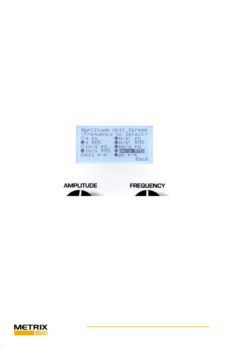
Amplitude Units
• Amplitude units that are seldom or never used can be turned
o by using the “Amplitude Units” feature, found by pressing
FREQUENCY dial > “Amplitude Units.”
• The “Amplitude Unit Screen” shows all 10 available amplitude
scales on model HI-913 Portable Vibraon Calibrator. Use the
FREQUENCY dial to highlight each scale and press the dial
to toggle the scale on or o. A lled circle next to the scale
indicates it is acve. An empty circle next to the scale indicates
it is inacve. Inacve scales do not appear when cycling through
scales using the AMPLITUDE dial during normal operaon.
• To go back to the “Calibraon Opons” menu use the
FREQUENCY dial to highlight “Back” then press.
Extending Low Frequency Operaon to 5 Hz
Firmware Opon: HI-913-LF5
Model HI-913 must be ordered with rmware oponHI-913-LF5 for the low
frequency response to be extended from 7 Hz to 5 Hz (420 CPM to 300 CPM). This
rmware can be added at any me. Contact Metrix for ordering and installaon
informaon.
The operaon of model HI-913 does not change if the HI-913-LF5 opon is
ordered. The minimum low frequency response will be 5 Hz instead of 7 Hz. Allow
for extra me for the shaker and sensor under test to sele when tesng at slow
speeds. The HI-913 has a pre-compensaon algorithm to reduce distoron. At
speeds below 10 Hz this algorithm takes 1-5 seconds to center vibraon on the
fundamental frequency and reach the desired amplitude.
Denion of Frequency Units
• Hertz (Hz) is dened as the number of periodic cycles per second and
it is a standard unit for measuring signal frequency.
Doc# 100929 • HI-913-Shaker • January 2018 - RevD Page 6 of 21
• CPM stands for Cycles Per Minute. CPM is commonly used for tesng
industrial sensors that monitor rotaonal vibraon. 1 Hz=60 CPM
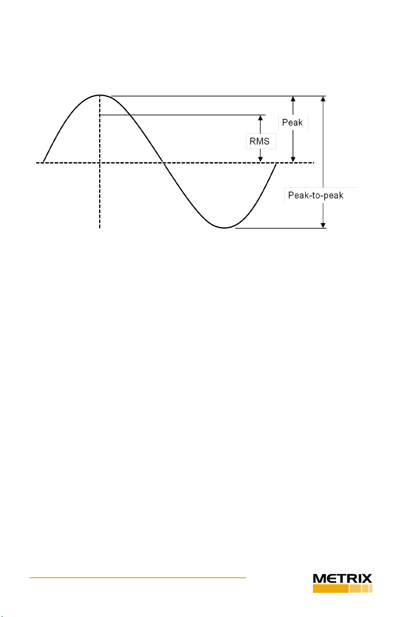
Amplitude Basics
• Root Mean Square (RMS) is a calculaon that takes the square root of
the average of the squared amplitudes from a set of data. This type of
measurement takes all amplitudes of a signal into account rather than
just one, making it an accurate tool for an overall calculaon.
• Peak (pk) bases calculaons on the highest value of the signal
generated during tesng. For a sinusoidal wave (as is produced by
the HI-913), the peak value is calculated by RMS*√2. The HI-913
does not measure a true peak value, but instead esmates the value
mathemacally based upon the RMS value.
• Peak-to-Peak (p-p) is a calculaon of the dierence between the
highest posive peak and the lowest negave peak of a recorded sine
wave. The
p-p value is calculated as two mes the peak value.
• Gravitaonal acceleraon (g) is the acceleraon experienced naturally
by objects in earth’s gravitaonal eld. It is approximately equal to
9.80665 m/s2.
Mounng Basics
Connecng Sensor to HI-913 Plaorm
1. Mang surfaces of the mounng plaorm and sensor should be at,
parallel and free of dirt, paint, epoxy, scratches, etc.
2. Threads in plaorm, sensor and adaptor (if needed) must match to
ensure a proper t and that tesng is free of errors. Clean any worn
threads with a tap or die and coat them in a silicone grease for best
results.
3. An adaptor may be needed to connect the sensor to the armature.
The HI-913 plaorm requires a ¼-28 thread.
Figure: Sinusoidal Wave

Doc# 100929 • HI-913-Shaker • January 2018 - RevD Page 7 of 21
4. Silicone grease can be applied to the mang surfaces and threads to
ensure good mechanical coupling. This is parcularly important when
tesng at high frequencies.
5. For threaded sensors, please follow the sensor manufacturer’s torque
recommendaon.
Tightening and Loosening Connecons
1. When ghtening or loosening the connecon between the sensor
and the HI-913 mounng plaorm, secure the mounng plaorm
with the supplied wrench.
2. It is important to keep sensors and xtures centered and straight
when aaching them to the HI-913 mounng plaorm. This will
ensure a stable, even connecon and eliminate potenal alignment
issues.
External Source Input
As an opon, it is possible to drive the HI-913 by using an external signal source
or a funcon generator. First, connect a signal source to the External Source
BNC Input located on the top right corner of the unit. To enable the EXTERNAL
SOURCE IN input, press the FREQUENCY dial to enter the “Calibraon Opons”
menu then rotate FREQUENCY dial to highlight and click on TEST SETTINGS. Next,
use FREQUENCY dial to highlight selecon next to “Source:” and toggle between
“Internal” and “External” by pressing the dial, select “External”.
1.When in external signal mode, the vibraon amplitude is
measured and displayed on the screen, however, the frequency
and amplitude of the shaker is controlled by the external source,
not by the HI-913. The frequency of the input signal is not
displayed on this mode.
2. The amplitude and sensivity values displayed on the screen are
for reference only. The measurements are not accurate while in
Ext Sig mode and do not fall under the published specicaons
for the product.
Do not exceed 1V RMS! Overdriving the unit may cause clipping,
unwanted distoron and damage to the unit.
Monitor Reference Output
The HI-913 is controlled by an internal shear mode quartz reference accelerometer.
The voltage output of the reference accelerometer can be monitored through the
available Monitor Reference BNC Output by connecng it to a readout device (e.g.
voltmeter or oscilloscope).
USB Connecon
The USB connecon for model HI-913 has no funconality unless power supply
accessories like HI-913-PS02 24 VDC power supply or HI-913-CALROUTE is ordered.
It is used at Metrix, Inc. during the manufacturing and calibraon processes.
Doc# 100929 • HI-913-Shaker • January 2018 - RevD Page 8 of 21
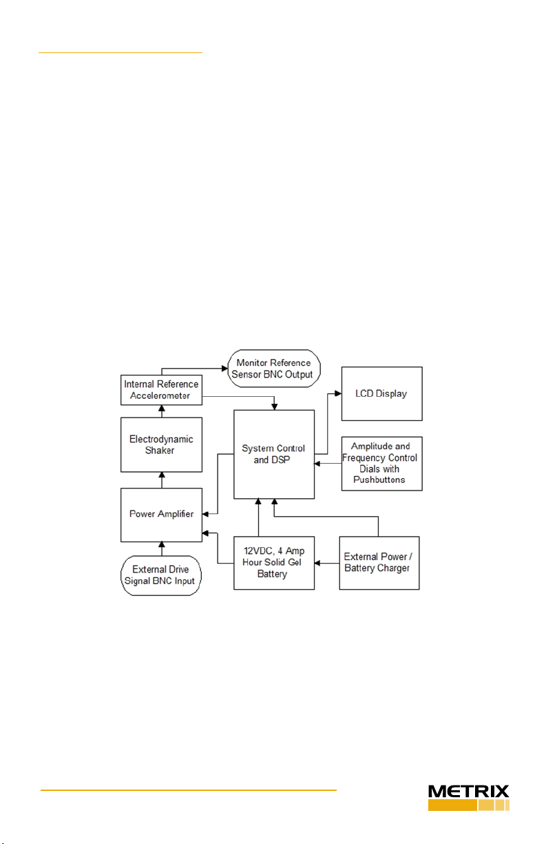
3. THEORY OF OPERATION
Instrumentaon
The Model HI-913 Portable Shaker Table internal electrical system is comprised of
several dierent mechanisms:
• Electrodynamic Shaker
• Power Amplier
• Reference Accelerometer
• Signal Generaon Electronics
• Sensor Signal Measurement Electronics
• LCD Digital Display
• Two Dials with Detent and Integrated Push Buons
• 12 VDC, 4 Amp Hour Solid Gel Baery
• External Charger
The LCD display connuously shows the frequency of the shaker drive signal and
the vibraon amplitude of the mounng plaorm as measured by the reference
accelerometer.
The reference accelerometer is a PCB Piezotronics ICP® quartz shear sensor,
integrated into the mounng plaorm. A calibraon “standard” maintained by
Metrix is used to calibrate the HI-913 as a complete system and provides NIST
traceability.
The power amplier is specially designed to provide the current required to drive
the electrodynamic shaker.
Doc# 100929 • HI-913-Shaker • January 2018 - RevD Page 9 of 21
The electronic signal processing system produces a variable frequency sine wave,
which becomes the source of the driving signal to produce the vibraon at the
mounng plaorm.
The frequency of the shaker drive signal is controlled by the front panel
FREQUENCY dial. The amplitude of the shaker drive signal is controlled through a
feedback loop, to maintain the stability of the actual moon. Adjusng the front
panel AMPLITUDE dial adjusts the target vibraon amplitude.
Pressing the FREQUENCY dial toggles the frequency units between CPM and Hz.
Pressing the FREQUENCY dial one more me enables the External Source Input.
Pressing the AMPLITUDE dial toggles the amplitude measurement units through
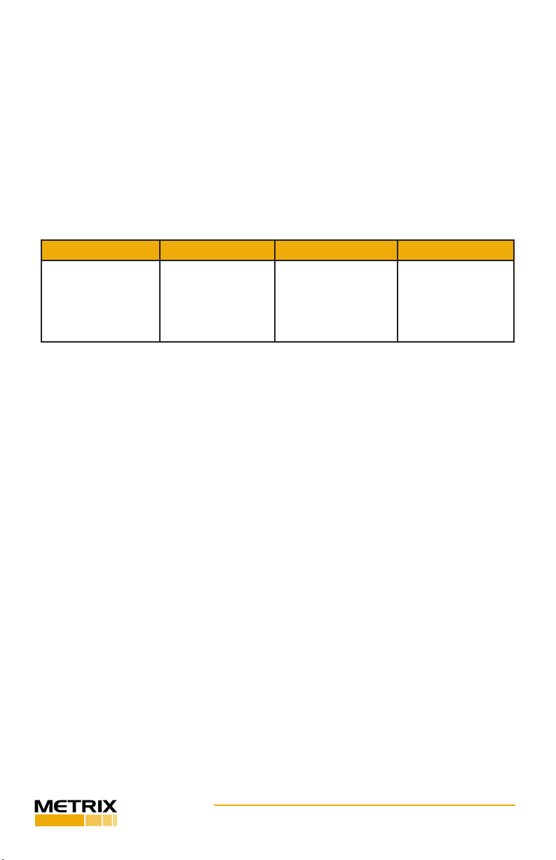
the following choices:
Frequency Acceleraon Velocity Displacement
Hz
CPM
External Signal
g’s pk
g’s RMS
m/s2 pk
m/s2 RMS
in/s pk
in/s RMS
mm/s pk
mm/s RMS
mils p-p
µm p-p
3.2 Baery and Charger
The Model HI-913 can be operated from AC line power or from its internal
rechargeable baery. When the external power supply is connected, it becomes
the primary power source, operang the unit while simultaneously charging the
baery.
NOTE: It is good pracce to perform calibraons on baery power. Disconnecng
from line power ensures a power surge will not cause the calibrator to power down
during test. If excess current is detected during use, the portable calibrator shuts
down to prevent damage.
Baery power is supplied by a sealed solid gel lead acid 12 VDC rechargeable
baery. The baery can be permanently damaged if completely drained. To
prevent damage, the HI-913 will automacally shut o when the baery power
level gets too low. Keeping the baery fully charged ensures the unit is always
ready for use.
Under mild operang condions, a fully charged baery will allow the HI-913 to
operate for up to 18 hours. The charge life of the baery depends on both the
length of use and the amount of power (dependent upon payload, frequency and
amplitude) required for a parcular test. When tesng requires high vibraon
levels, the charge life will be shorter than during less rigorous tesng. For example,
connuous tesng of a 100 gram payload at 10 g pk will drain the baery charge in
approximately 1 hour.
A “Baery Life” indicator is displayed on the LCD screen to approximate the unit’s
remaining charge life. Replacement baeries (Model HI-913 BAT01) and power
supplies/chargers (Model HI-913-PS01) are available from Metrix, Inc.
Doc# 100929 • HI-913-Shaker • January 2018 - RevD Page 10 of 21
The HI-913 calibrators connuously monitor the state of baery charge during
operaon, storage and charging. During operaon, if the baery capacity falls
near minimum, the unit will shut o aer approximately 2 minutes of inacvity
rather than the usual 20 minutes. During storage, if the baery voltage falls near
the minimum, the unit will go into deep sleep, requiring connecon of AC power
and reset of me and date before resumpon of operaon. During charging, the
unit connuously displays charging indicaon and state of charge, depending upon
operaon level and me of charge.
When operang the HI-913 at high amplitudes and heavy payloads
with the baery charger plugged in, the current draw to the shaker
and amplier can be large enough to overload the charging circuit
resulng in an unstable output signal. Operang the HI-913 under
these condions can result in damage to the electrical components in
the system. In order to re-establish a stable output signal, turn down
the amplitude level of the HI-913 or unplug the charger.
Baery Informaon and Care
• The unit is delivered in a parally charged state. Fully charge unit for 20 hours
before using for the rst me. (The unit cannot be overcharged by keeping it
plugged into the power supply.)
• To recharge the unit, use only the universal power supply included. All
baeries lose energy from self-discharge over me and more rapidly at higher
temperatures. A full charge cycle can take up to 20 hours.
• If not used for a prolonged period of me, recharge every 2 months.
• Suggested Best Pracce: Charge unit fully prior to eld use. Recharge the unit
as soon as possible aer use.
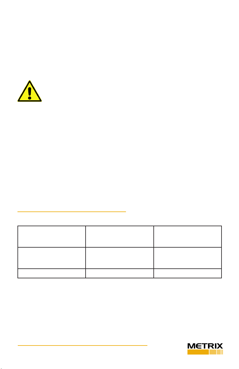
4. SPECIFICATIONS AND PERFORMANCE
General
Frequency Range
(operang, 100 gram
payload)
7 Hz - 10 kHz 420 - 600 k CPM
Maximum Amplitude
(100 Hz no payload)
20 g pk
15 in/s pk
50 mils pk-pk
196 m/s2 pk
380mm/s pk
1270 µm pk - pk
Maximum Payload[1] 800 gram 800 gram
[1] Operang range reduced at higher payloads. Reference manual for full details
Indice


