metrotek Bercut-ETL Manuale utente

Bercut-ETL
Ethernet/Gigabit Ethernet loopback
Operating manual
Version 1.1.2-0, 2012
Metrotek

c
Metrotek, 2006—2012
No part of this document may be reproduced in any form or by any means
without the written permission of Metrotek. Metrotek retains the right to make
changes to the hardware, software of Bercut-ETL and to this document at
any time, without notice.

3
Contents
1 General description 5
2 Supply kit 7
3 Overview 9
3.1 Appearance . . . . . . . . . . . . . . . . . . . . . . . . . . . . . . . 9
3.2 External connectors . . . . . . . . . . . . . . . . . . . . . . . . . . 11
3.3 Setting-up procedures . . . . . . . . . . . . . . . . . . . . . . . . . 13
4 Loopback 15
4.1 Loopback adjustment . . . . . . . . . . . . . . . . . . . . . . . . . 17
5 Remote management 19
5.1 Remote control via Telnet potocol . . . . . . . . . . . . . . . . . . 19
5.2 OAM . . . . . . . . . . . . . . . . . . . . . . . . . . . . . . . . . . . 20
5.3 ET discovery . . . . . . . . . . . . . . . . . . . . . . . . . . . . . . 21
5.4 Upgrading software versions . . . . . . . . . . . . . . . . . . . . . . 22
5.4.1 Device preparing for upgrading software versions . . . . . . 22
5.4.2 PC setup for device software upgrading . . . . . . . . . . . 23
6 Troubleshooting 25
Bercut-ETL. Operating manual

4
Bercut-ETL. Operating manual

5
1. General description
Ethernet/Gigabit Ethernet loopback device Bercut-ETL is intended for
loopback performing at the physical, data link, network and transport layers
of the OSI model in IP/Ethernet networks.
Incoming traffic is being retransmitted backward with possibility of source
and destination MAC/IP addresses and TCP/UDP port numbers swapping.
To switch between loopback layers Lbutton is used. The device allows to
perform loopback control via OAM protocol and remote control via TELNET
protocol.
Bercut-ETL. Operating manual

6
Bercut-ETL. Operating manual
7
2. Supply kit
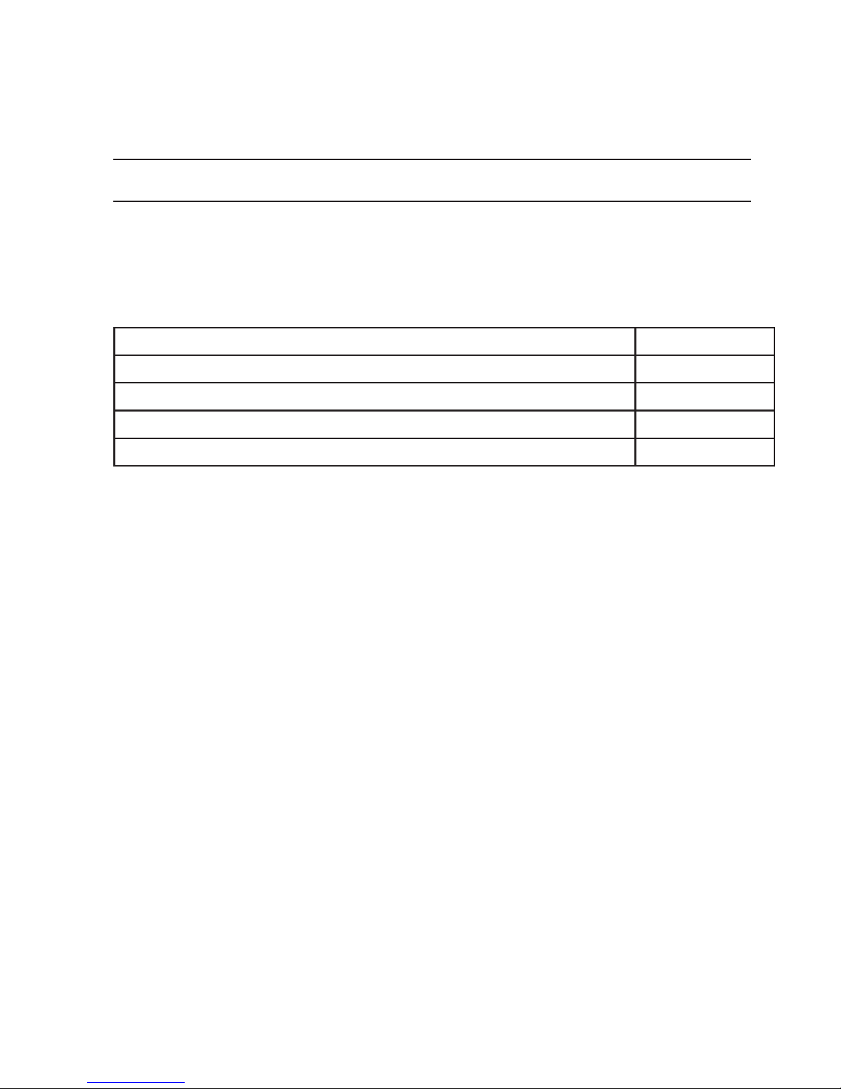
Table 2.1. Supply kit
Item Quantity
Device Bercut-ETL 1
Power supply unit with connecting cable 1
PC connecting cable 1
Changeable nozzle 4
Bercut-ETL. Operating manual

8
Bercut-ETL. Operating manual
9
3. Overview
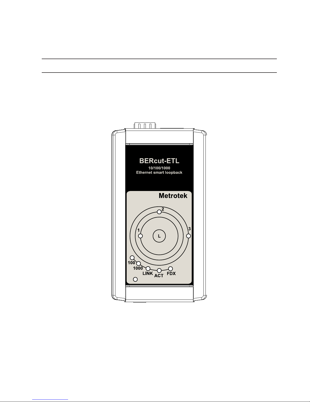
3.1 Appearance
Figure 3.1. Appearance of Bercut-ETL
LEDs
LEDs are located on the front panel of Bercut-ETL. They show loopback
layer, Ethernet links and power supply unit connection state.
Loopback layer indicators
•1— layer 1 loopback;
Bercut-ETL. Operating manual

10 Overview
•2— layer 2 loopback;
•3— layer 3 loopback;
•1+3 — layer 4 loopback.
For more details see section 4.
Link speed indicators
Table 3.1. Speed LEDs
Speed LED LEDs color
10 Mbit/s 100 and 1000 green
100 Mbit/s 100 green
1000 Mbit/s 1000 green
State LEDs
LINK — link state:
•green — connection at physical layer is established;
•off — no connection.
ACT — data reception/transmission state:
•green — data is being received/transmitted at the moment;
•off — no data is being received or transmitted at the moment.
FDX — Ethernet interface state:
•green — full-duplex connection is established;
•off — half-duplex connection is established.
Power — external power supply (indicator is located in the left bottom corner
of front panel):
•green — power supply unit is plugged in;
•red — device malfunction.
— the button for loopback mode control. To switch between layers 1, 2,
3, 4 or turn loopback off, press this button as many time as needed.
Bercut-ETL. Operating manual
Indice
Manuali Hardware di rete popolari di altre marche

Matrix Switch Corporation
Matrix Switch Corporation MSC-HD161DEL Manuale utente

B&B Electronics
B&B Electronics ZXT9-IO-222R2 Manuale utente

Yudor
Yudor YDS-16 Manuale utente

D-Link
D-Link ShareCenter DNS-320L Manuale utente

Samsung
Samsung ES1642dc Istruzioni per l’uso

Honeywell Home
Honeywell Home LTEM-PV Istruzioni per il montaggio


