5
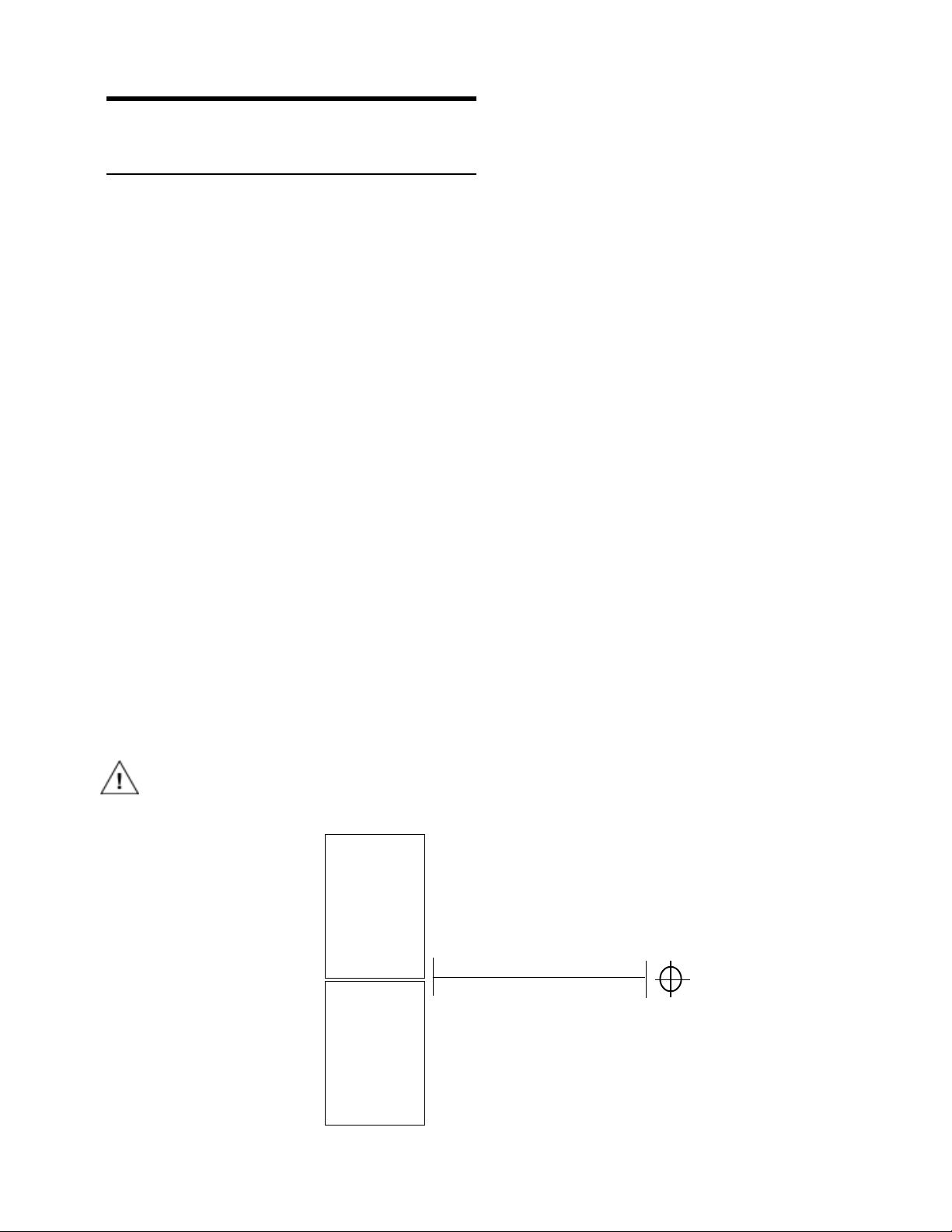
The Modular Rear Panel
Therearpanelofthe USW-1P hastwoslotsformodules.
ThetopslotcontainstheAudioInputModule;thebottom
slot contains the optional Remote Monitoring System™
(RMS) Module. A blank plate covers the bottom slot if
RMSisnotinstalled.
udio Input
There are three, interchangeable Audio Input Modules
with optimized connectors and controls for different app-
lications.Eachmodulehasa24VFanconnectortopoweran
optionalfan(seefansectiononpage6).
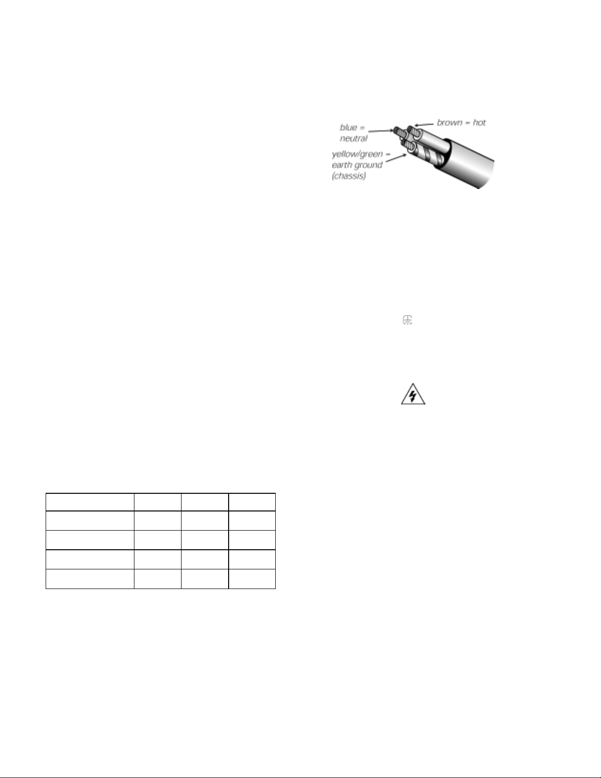
Each module uses a three-pin, female XLR audio input
connectorwitha10kΩbalancedinputimpedancewiredwith
thefollowingconvention:
Pin1 — 220kΩtochassisandearthground(ESDclamped)
Pin2 —Signal+
Pin3 —Signal-
Case — Earth(AC)groundandchassis
Pins 2 and 3 carry the input as a differential signal. Use
standardaudiocables withXLRconnectorsforbalanced
signalsources.AsingleaudiosourcecandrivemultipleUSW-
1Pswithaparalleledinputloop,creatinganunbufferedhard-
wiredloopconnection,withnegligiblelossinsignallevel.
Forexample,sincetheinputimpedanceofoneUSW-1Pis10
kΩ,looping20USW-1Pproducesabalancedinputimped-
ance of 500Ω. With a 150Ωaudio source, the 500Ωload
resultsinonlya2.28dBloss.
For drawings of the modules refer to page 12.
Looping Audio Input Module
Thisstandardmoduleusesabalanced,femaleXLRconnector
foraudioinputandamaleXLRloopconnectortointerconnect
multiplespeakers.Theaudioinputconnectorishardwired
withpin2hottocomplywithaudioindustrystandards.The
loopconnector,wiredinparalleltotheaudioinput,transmits
the input signal even if the USW-1P is turned off for any
reason.
Summing Audio Input Module
ThismodulehastwobalancedfemaleXLRconnectors.The
secondfemaleXLRconnectorfunctionsasasumminginput.
Applyingasignal tooneoftheinputsresultsinanormal
signallevel.Utilizingbothsumminginputscreatesacor-
rectlysummedmonosignalwitheachinput6dBbelowthe
levelofasingleinput.Thisisaneffectivemethodfordistrib-
utingbothsidesofastereosignaltoasingleUSW-1Pwithout
requiringexternallevelcontrol.
Looping, Polarity, and Attenuating Audio
Input Module
Thismodulehasabalanced,femaleXLRaudioinputconnec-
tor,amaleXLRloopconnector,aninputpolarityswitch,and
alevelattenuatorknob.Theinputpolarityswitchoffersa
convenientmethodofreversingthepolarityofthespeaker.
Whentheinputpolarityswitchisintheup(+)position,pin
2ishotrelativetopin3,resultinginapositivepressurewave
whenapositivesignalisappliedtopin2.Whentheswitchis
down(-),pin3ishotrelativetopin2,resultinginapositive
pressurewavewhenapositivesignalisappliedtopin3.The
levelattenuatorknoboperatesbetween0dB(nolevelat-
tenuation)inafullyclockwisepositionto–12dBinafully
counterclockwiseposition.
Remote Monitoring System
TheUSW-1PcanbeequippedtooperatewiththeRemote
MonitoringSystem(RMS)networkandsoftwareapplica-
tion.RMSdisplayssignalandpowerlevels,driverstatus.
limiter activity, the state of the polarity switch, attenuator
level, and amplifier temperature for all speakers in the
networkonaWindows-basedPC.RMScanalsobeconfig-
uredtoenablespeakermuting.RMSisanexcellentfield-
diagnostictoolthatremovestheguessworkfromtrouble-
shootingduringaperformance.AllMeyerSpeakerswith
RMScanbeintegratedonthesamenetwork.Installingan
RMSmodulerequiresonlyaPhillipsscrewdriver.Contact
MeyerSoundformoreinformationaboutRMS.
Amplification, Limiting, and
Cooling System
mplification and Limiting
EachdriverintheUSW-1Pispoweredbyonechannelofa
proprietaryMeyerSoundamplifierutilizingcomplementary
powerMOSFEToutputstages(classAB,bridged).TheUSW-1P
employs two separate methods of limiting: Excursion
Limiting which protects the drivers from over excursion
andSubChannelLimitingwhichpreventsthedriversfrom
damageduetothermaloverload.
LimiteractivityfortheExcursionandSubchannelisindi-
catedbytwoyellowLimitLEDsontherearpanel(theEXC.
Limit LED is above the SUB limit LED). See page 12 for a
diagramoftheuserpanel.
TheUSW-1Pperformswithinitsacousticalspecifications
andoperatesatanormaltemperatureifthelimitLEDsareon
fornolongerthantwoseconds,andoffforatleastonesecond.
DifferentialInputs