Microchip Technology MRF24WN0MA Manuale utente

2015 Microchip Technology Inc. Advance Information DS50002410A-page 1
MRF24WN0MA/MB
Features
• IEEE 802.11b/g/n Compliant Transceiver
• 2.4 GHz IEEE 802.11n Single Stream 1x1
• SPI Interface to Host Controller (4-wire including
interrupt)
• Works with Microchip's MPLAB®Harmony
Integrated Software Framework
• Fully Integrated Wireless Module with Voltage
Regulation, Crystal, RF Matching Circuitry, Power
Amplifier (PA), Low Noise Amplifier (LNA), and
PCB Trace Antenna
• Ultra-Small W.FL Connector for External
Antennas (MRF24WN0MB)
• Compact Surface Mount Module: 0.700" x 1.050"
x 0.085“ (17.8 mm x 26.7 mm x 2.2 mm)
• Castellated Surface Mount Pads for easy and
reliable PCB mounting
• Environmentally Friendly, RoHS Compliant
Operational
• Single Operating Voltage: 3.15V to 3.45V (3.3V
typical)
• Temperature Range: -40°C to +85°C Industrial
• Low-Current Consumption:
- RX mode: 64 mA (typical)
- TX mode: 246 mA at 18 dBm (typical)
• Power Saving Mode:
- Hibernate: 10 µA (typical)
RF/Analog
• Frequency: 2.412 to 2.472 GHz
• Channels: 1-13
• Modulation: DSSS, CCK, BPSK, QPSK, 16QAM,
64QAM
• Sensitivity: -94 dBm
Antenna
• Integral PCB Trace Antenna (MRF24WN0MA)
• External Antenna (MRF24WN0MB)
Compliance
• Modular Certified for the United States (FCC) and
Canada (IC)
• European R&TTE Directive Assessed Radio
Module
• Australia, New Zealand, Korea, Taiwan, and
Japan
Applications
• Utility and Smart Energy
• Consumer Electronics
• Industrial Controls
• Remote Device Management
• Retail
• Medical, Fitness, and Health Care
2.4 GHz IEEE 802.11b/g/n Wireless Module

MRF24WN0MA/MB
DS50002410A-page 2 Advance Information 2015 Microchip Technology Inc.
Table of Contents
1.0 Device Overview .......................................................................................................................................................................... 3
2.0 Circuit Description .......................................................................................................................................................................11
3.0 Application Information............................................................................................................................................................... 15
4.0 Regulatory Approval ................................................................................................................................................................... 21
5.0 Electrical Characteristics ............................................................................................................................................................ 27
Appendix A: Revision History............................................................................................................................................................... 29
The Microchip Web Site ....................................................................................................................................................................... 31
Customer Change Notification Service ................................................................................................................................................ 31
Customer Support ................................................................................................................................................................................ 31
Product Identification System............................................................................................................................................................... 33
TO OUR VALUED CUSTOMERS
It is our intention to provide our valued customers with the best documentation possible to ensure successful use of your Microchip
products. To this end, we will continue to improve our publications to better suit your needs. Our publications will be refined and
enhanced as new volumes and updates are introduced.
If you have any questions or comments regarding this publication, please contact the Marketing Communications Department via
Most Current Data Sheet
To obtain the most up-to-date version of this data sheet, please register at our Worldwide Web site at:
http://www.microchip.com
You can determine the version of a data sheet by examining its literature number found on the bottom outside corner of any page.
The last character of the literature number is the version number, (e.g., DS30000000A is version A of document DS30000000).
Errata
An errata sheet, describing minor operational differences from the data sheet and recommended workarounds, may exist for current
devices. As device/documentation issues become known to us, we will publish an errata sheet. The errata will specify the revision
of silicon and revision of document to which it applies.
To determine if an errata sheet exists for a particular device, please check with one of the following:
• Microchip’s Worldwide Web site; http://www.microchip.com
• Your local Microchip sales office (see last page)
When contacting a sales office, please specify which device, revision of silicon and data sheet (include literature number) you are
using.
Customer Notification System
Register on our web site at www.microchip.com to receive the most current information on all of our products.

2015 Microchip Technology Inc. Advance Information DS50002410A-page 3
MRF24WN0MA/MB
1.0 DEVICE OVERVIEW
The MRF24WN0MA and MRF24WN0MB are low-
power, 2.4 GHz, IEEE 802.11n compliant, surface
mount modules containing all associated RF
components: crystal oscillator, bypass and bias
passives with integrated MAC, baseband, RF and
power amplifier, and built-in hardware support for
encryption. Refer to Figure 1-1.
The integrated module design frees the designer from
RF and antenna design tasks and regulatory
compliance testing, ultimately providing faster time to
market.
The MRF24WN0MA/MB modules are designed to be
used with Microchip's MPLAB® Harmony Integrated
Software Framework. The integrated framework imple-
ments the Application Programming Interface (API)
that is used for command and control, management
and data packet traffic.
The MPLAB Harmony basic framework is available via
a free download from the Microchip web site at
http://www.microchip.com/harmony. For more informa-
tion on the basic framework and available release ver-
sions, refer to “MPLAB®Harmony Release Notes and
Contents” found under the Documentation tab.
The MRF24WN0MA module is approved for use with
the integrated PCB trace antenna. The MRF24WN0MB
module is approved for use with specific external
antenna types that are certified with the module. An
ultra-small coaxial connector (W.FL) is provided on the
module for connection to the external antenna. Refer to
Section 3.3, "External Antenna Types" for a listing of
approved antenna types.
The MRF24WN0MA/MB modules received the regula-
tory approvals for modular devices in the United States
(FCC) and Canada (IC). Modular approval removes the
need for expensive RF and antenna design, and
enables the end user to place the MRF24WN0MA/MB
modules inside a finished product without requiring a
regulatory testing for an intentional radiator (RF trans-
mitter).
The MRF24WN0MA/MB module is an R&TTE Directive
assessed radio module for operation in Europe. The
module tests can be applied toward final product
certification and Declaration of Conformity (DoC).
Table 1-1 lists the MFR24WN0 module’s family types.
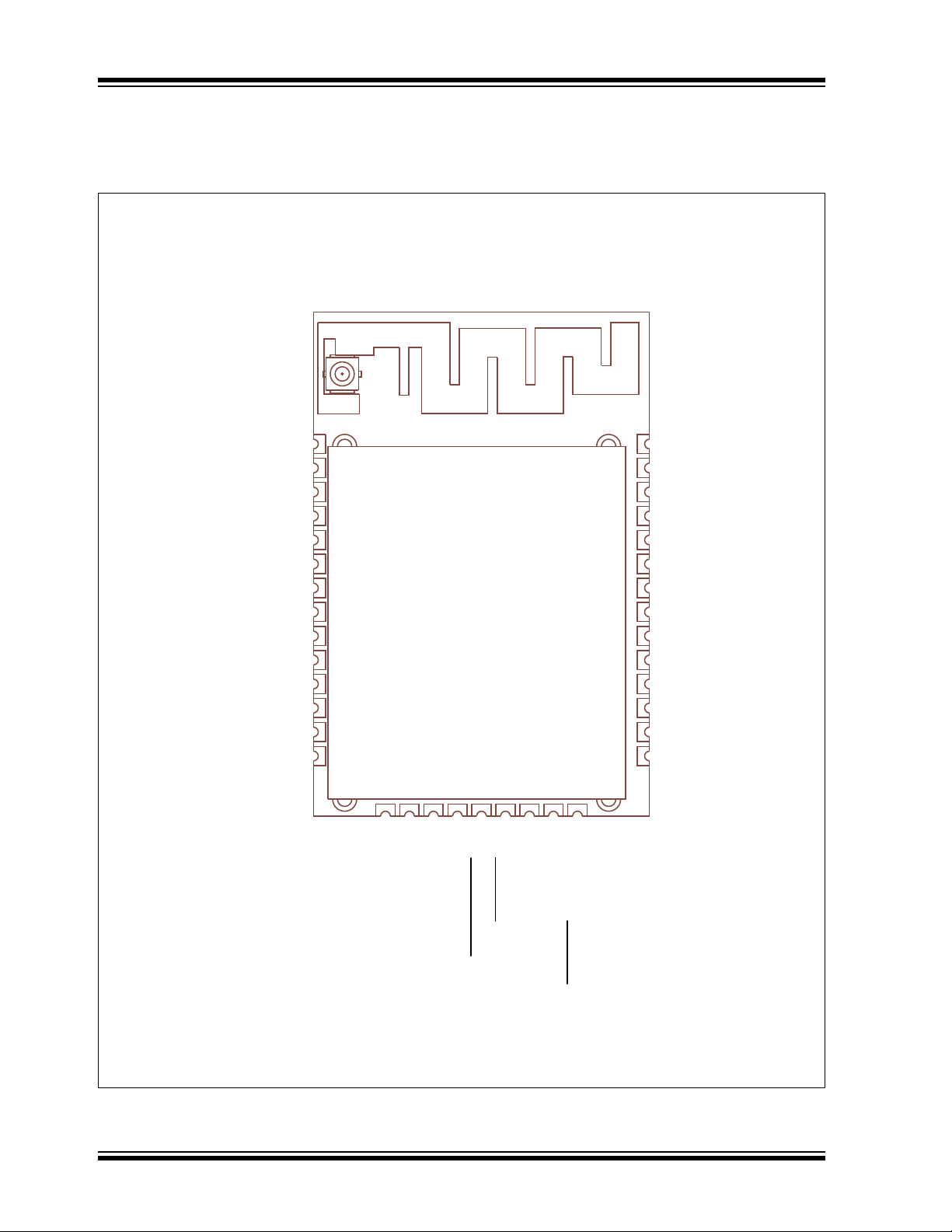
FIGURE 1-1: MRF24WN0MA/MB BLOCK DIAGRAM
TABLE 1-1: MRF24WN0 FAMILY TYPES
Device Antenna
MRF24WN0MA Integral
MRF24WN0MB External
Matching
Circuitry
Wi-Fi
SoC
Flash
PCB Trace
Antenna
(MRF24WN0MA)
External Antenna
Connector
(MRF24WN0MB)
Power
MRF24WN0MA/MB 2.4 GHz IEEE 802.11 b/g/n Module
SPI
Hibernate
Interrupt
MRF24WN0MA/MB
DS50002410A-page 4 Advance Information 2015 Microchip Technology Inc.
1.1 Interface Description
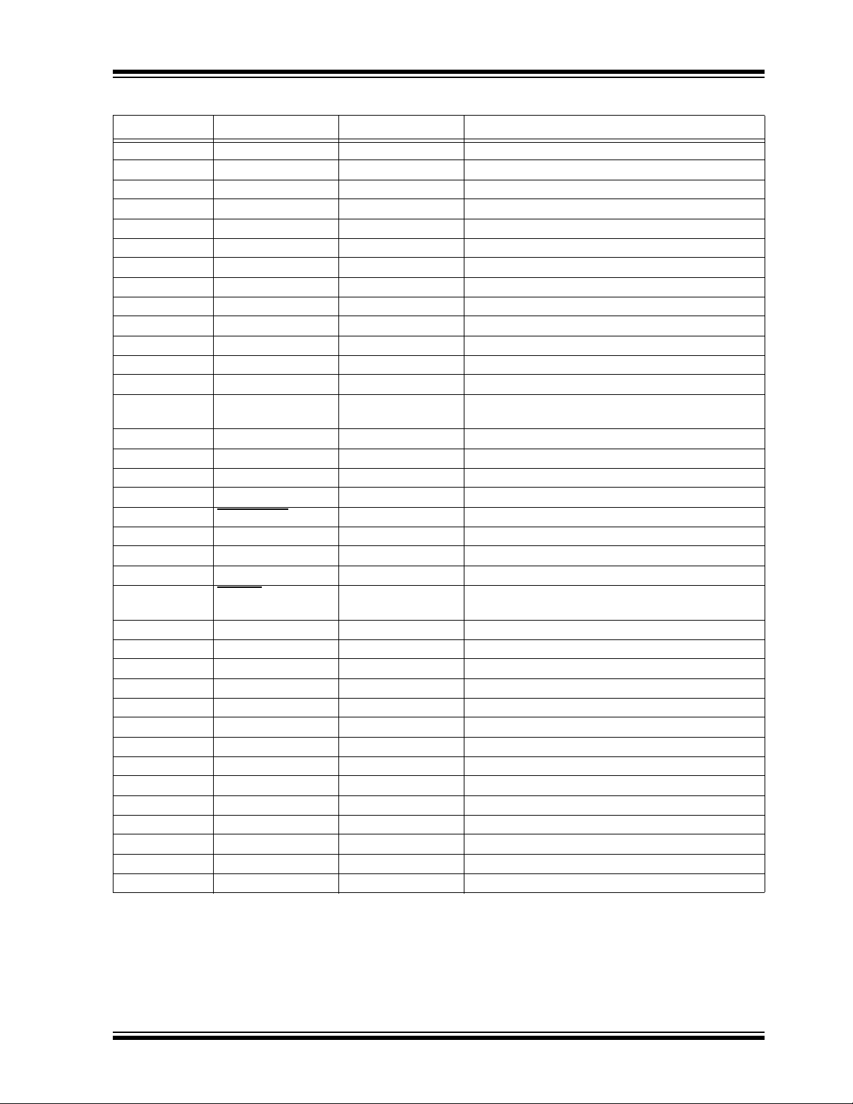
Figure 1-2 shows the MRF24WN0MA/MB pin diagram. Ta bl e 1- 2 describes the MRF24WN0MA/MB pins.
FIGURE 1-2: MRF24WN0MA/MB PIN DIAGRAM
37 GNDGND 1
TEST 2
GND 3
VDD 4
NC 5
NC 6
NC 7
NC 8
NC 9
NC 10
NC 11
NC 12
SPI_CLK 13
SPI_MISO 14
36 GND
35 VDD
34 GND
33 NC
32 NC
31 NC
30 NC
29 NC
28 NC
27 GND
26 NC
25 NC
24 GND
VDD 15
GND 16
TEST 17
TEST 18
HIBERNATE 19
SPI_INT 20
MODE0 21
SPI_MOSI 22
SPI_CS/MODE1 23
2015 Microchip Technology Inc. Advance Information DS50002410A-page 5
MRF24WN0MA/MB
TABLE 1-2: PIN DESCRIPTIONS
Pin Name Type Description(1)
1GND Power —
2 TEST Test Do not connect
3GND Power —
4 VDD Power —
5 NC Reserved Do not connect
6 NC Reserved Do not connect
7 NC Reserved Do not connect
8 NC Reserved Do not connect
9 NC Reserved Do not connect
10 NC Reserved Do not connect
11 NC Reserved Do not connect
12 NC Reserved Do not connect
13 SPI_CLK DI SPI clock input
14 SPI_MISO DO SPI data output; pull-down to GND with 10 kilo-ohm
resistor
15 VDD Power —
16 GND Power —
17 TEST Test Do not connect
18 TEST Test Do not connect
19 HIBERNATE DI Lowest Power State (active-low)
20 SPI_INT DO SPI interrupt output (active-low)
21 MODE0 DI Mode select 0; Connect to GND(2)
22 SPI_MOSI DI SPI data input
23 SPI_CS/MODE1 DI SPI Chip Select/Mode select 1; Connect to VDD via
10 kilo-ohm pull-up resistor(2)(3)
24 GND Power —
25 NC Reserved Do not connect
26 NC Reserved Do not connect
27 GND Power —
28 NC Reserved Do not connect
29 NC Reserved Do not connect
30 NC Reserved Do not connect
31 NC Reserved Do not connect
32 NC Reserved Do not connect
33 NC Reserved Do not connect
34 GND Power —
35 VDD Power —
36 GND Power —
37 GND Power —
Legend: A = Analog, D = Digital, I = Input, O = Output
Note 1: For NC = No Connect pins, do not make any connection. The module is configured with internal pull-up
and pull-down resistors.
2: Refer to Section 2.2, "MODE0 and MODE1 Pins"
3: Refer to Section 2.3, "SPI Port Pins"

MRF24WN0MA/MB
DS50002410A-page 6 Advance Information 2015 Microchip Technology Inc.
1.2 Mounting Details
Figure 1-3, Figure 1-4 and Figure 1-5 show the physical dimensions and the mounting details of the module.
Figure 1-6 and Figure 1-7 show the recommended host PCB footprint and layout.
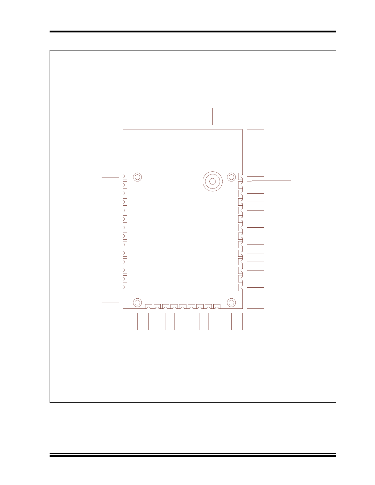
FIGURE 1-3: MRF24WN0MA/MB MODULE PHYSICAL DIMENSIONS (TOP AND SIDE VIEW)
'LPHQVLRQVDUHLQLQFKHV
7ROHUDQFHV
3&%RXWOLQH
3&%WKLFNQHVV
2015 Microchip Technology Inc. Advance Information DS50002410A-page 7
MRF24WN0MA/MB
FIGURE 1-4: MRF24WN0MA/MB MODULE PHYSICAL DIMENSIONS (BOTTOM VIEW)
'LPHQVLRQVDUHLQLQFKHV

MRF24WN0MA/MB
DS50002410A-page 8 Advance Information 2015 Microchip Technology Inc.
FIGURE 1-5: MRF24WN0MA/MB MODULE MOUNTING DETAILS
Keep area around antenna
(approximately 1.25 inches) clear
of metallic structures for
best performance.
1.25
1.25
Edge of
Host PCB
Ground Plane
0.2550.795
(Top View)
Dimensions are in inches

2015 Microchip Technology Inc. Advance Information DS50002410A-page 9
MRF24WN0MA/MB
FIGURE 1-6: MRF24WN0MA/MB RECOMMENDED HOST PCB FOOTPRINT
*URXQG3ODQH
+RVW3&%
(GJH
6KLHOG3DGV;
GLDPHWHU
'RQRWORFDWH+RVW
3&%WRSOD\HUFRSSHU
XQGHU6KLHOG3DGV
.HHSRXWDUHD

MRF24WN0MA/MB
DS50002410A-page 10 Advance Information 2015 Microchip Technology Inc.
FIGURE 1-7: MRF24WN0MA/MB HOST PCB EXAMPLE LAYOUT
1.3 Soldering Recommendations
The MRF24WN0MA/MB wireless module was assem-
bled using the IPC/JEDEC J-STD-020 Standard lead-
free reflow profile. The MRF24WN0MA/MB module
can be soldered to the host PCB using standard leaded
and lead-free solder reflow profiles.
To avoid damaging the module, adhere to the following
recommendations:
• Solder reflow recommendations are provided in
the Microchip Application Note, AN233 "Solder
Reflow Recommendation" (DS00233)
• Do not exceed a peak temperature (TP) of 250°C
• Refer to the solder paste data sheet for specific
reflow profile recommendations from the vendor
• Use no-clean flux solder paste
• Do not wash as moisture can be trapped under
the shield
• Use only one flow. If the PCB requires multiple
flows, apply the module on the final flow.
Best
Okay Okay
Okay
No Copper
in these Areas
Questo manuale è adatto per i seguenti modelli
1
Indice
Altri manuali Microchip Technology Modulo wireless

Manuali Modulo wireless popolari di altre marche


Cooper Wiring Devices
Cooper Wiring Devices ESPIRE RF RFAPM Manuale utente

Yuga
Yuga CLM920 Manuale utente

Waldmann
Waldmann TALK Bluetooth Manuale utente

Telit Wireless Solutions
Telit Wireless Solutions UC864-G Manuale di installazione

Ebyte
Ebyte E07-900M10S Manuale utente

Quectel
Quectel SC690A Series Supplemento

Panasonic
Panasonic INDUSTRY PAN9028 Guida rapida alla configurazione

Ebyte
Ebyte E70-433NW30S Manuale utente

LongSung Technology
LongSung Technology U9507E Manuale utente

Wistron NeWeb
Wistron NeWeb DNUR-S2 Manuale utente

Ebyte
Ebyte E49-400M20S4 Manuale utente

RF-Star
RF-Star SimpleLink RF-BM-2652P1 CC2652P Manuale utente