Microtek IN-600VA Manuale utente

WINNER OF SMART LIVING AND EFY AWARDS

Congratulations on selecting Micro Controller Based MICROTEK
Digital Inverter & subsequently joining the family of the millions of
satisfied users of Microtek Products.
Before using this inverter, Please read this manual carefully to
familiarize yourself with all its features, controls and safety
precautions.
Enjoy Uninterrupted Power !
1
AN ISO 9001:2000 COMPANY
WINNER
SMART LIVING & EFY AWARDS
WINNER
SMART LIVING & EFY AWARDS

2

TABLE OF CONTENTS
The Product - Page 04
Salient Features - Page 04
Front Panel - Page 05
Back Panel - Page 06
Load Chart - Page 07
Noise on Inverter Mode - Page 07
Troubleshooting - Page 08
Bypassing the Inverter - Page 10
Technical Specifications - Page 11
Servicing - Page 12
Warranty - Page 12
Safety Instructions - Page 14
Important - Page 14
Going on Vacations - Page 14
3

THE PRODUCT
Inverter is a electronic power source which stores the energy in batteries connected to it when the AC source is present and
converts this energy automatically to AC power when the Input AC source fails and automatically feeds generated AC
power to the loads connected & returns to mains when the AC source comes back on the input side.
SALIENT FEATURES
MICRO CONTROLLER BASED DIGITAL INVERTERS are designed using latest state-of-the-art Technology for Better
Performance and High Reliability. The Digital Technology used enhances the life of the battery and minimum effort has
to be put for maintenance.
7MICRO-CONTROLLER BASED Intelligent Control Design.
7Display Indications (Status & Fault)
7CCCV Technology with Auto Trickle Mode
7Smart Overload Sense and Short Circuit Protection
7Battery State Monitoring
7Easily Serviceable
7Multi Stage Battery Charger
7Optional UPS mode for Computer Applications
4

FRONT PANEL
I. LED Indications
1. Mains ON.
2. Inverter ON.
3. Battery Charging.
LED Continuously Glows
when Charged.
LED Blinks when Battery is
Charging.
4. Fuse Blown.
5. Inverter Overload.
6. Battery Low.
II. Switch
7. Power On / Off & Reset.
5
7
1 2 3 5 6 4
MAINS
ON
INVERTER
ON
BATTERY
CHARGING
STATUS
INVERTER
OVERLOAD
BATTERY
LOW
FUSE
BLOWN
FAULT
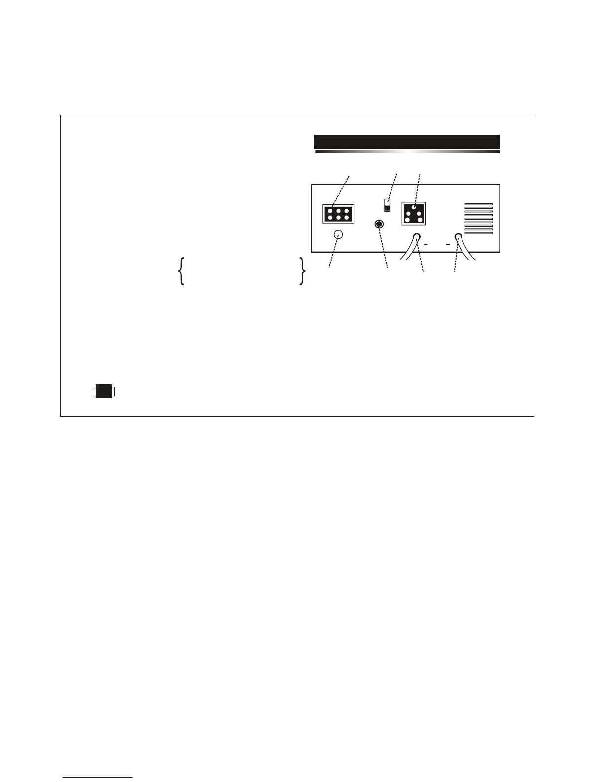
BACK PANEL
N E L
7
16
2
3
45
1. Mains Input Terminal Block for AC input.
2. Circuit Breaker for mains overload / short circuit protection.
(4Amps/7Amps for IN-600VA Model, 8Amps/10Amps for
IN-800VA Model & 10Amps/16Amps for IN-1400VA Model).
3. Output socket for load.
4. Positive Battery Lead.
5. Negative Battery Lead.
.
7. Fuse (10Amp Slow Blow for all models) for Charger.
6 Slide Switch to Select the Maximum Charging Voltage.
(HIGH= 14.2V DC / Standard (STD)= 13.8 V DC).
Select the appropriate Voltage as recommended by the Battery
Manufacturer/Supplier.
CAUTION: Proper selection of switch position is recommended based on the battery manufacturers specifications,
for proper backup and also to avoid any damage to the battery due to wrong selection.
In case of IN-600VA / IN-800VA - 12V Batt. Sys.
In case of IN-1400VA - 24V Batt. Sys.
6

LOAD CHART
The following Data should be used for calculating the total load in VA, while using the Inverter.
LOAD STANDARD RANGE GENERAL RANGE
1. Tube light new / good choke 75 VA 60 VA ~ 75 VA
2. Tube light with old / inferior choke 105 VA 75 VA ~ 105 VA
3. Electric bulb As per actual Wattage (eg. 60 W Bulb as 60 VA)
4. Fan below 48” size 100 VA 75 VA ~ 100 VA
5. Fan above 48” size 125 VA 100 VA ~ 125 VA
6. Television 14” / 21” 150 VA 125 VA ~ 150 VA
7. C. F. L. 9 W / 11 W 40VA 25 VA ~ 40 VA
Generally on inverter mode, a noise may be observed from tube light / fan, which is due to the following reasons:-
1. Because of inferior quality choke. 2. Weak / Leaky capacitor in fan.
These noises may not be present while on mains mode, but shall be on the inverter mode because of TPZi waveform, which
allows higher backup as compared to Sine Wave (Mains Waveform) in inverter mode with noise as nuisance.
This can be reduced by Loading the inverter output with a R-C Circuit:-
For 600/800VA :Use a Resistance of 22 Ohms / 150W in series with a Polyester Capacitor of 2.5MFD / 440V.
For 1400VA : Use a Resistance of 22 Ohms / 150W in series with a Polyester Capacitor of 4MFD / 440V.
NOTE:- Loading of the inverter with a R-C Circuit reduces the backup time.
NOISE ON INVERTER MODE
7

TROUBLE SHOOTING
Problem Possible Cause / Action Suggested
1. Main Supply is Normal but:-
a) Inverter is working on battery a) Dead wall socket. Line AC input connections are
loose.
b) Fuse Blown b) Check Charger Fuse at the rear. If blown change it
to 10Amp rating. If fuse still blows call authorised
service engineer.
c) No output from inverter c) Check Circuit Breaker at the Rear. Push the Circuit
Breaker (Reset), to Switch On the output. If it trips
again, call electrician to check shorting/overload in
the load wiring.
2. Inverter trips frequently at inverter mode. The load is more. Reduce the load and reset the
inverter.
3. Inverter Mode but no power:-
a) Overload a) Reduce the load and turn the reset switch on the
front panel ON-OFF-OFF-ON.
LED
Inverter ON
Green LED Glows
LED
Mains Fuse Blown
Red LED Glows
LED
Overload
Red LED Glows
8

TROUBLE SHOOTING
Problem Possible Cause / Action Suggested
b) Low Battery b) Battery has discharged. Recharge the battery after
the mains restoration.
c) Short Circuit c) Check the wiring and reduce the load and turn the reset
switch on the front panel ON-OFF-OFF-ON.
4. Backup time less. a) Check battery water and charge the battery with mains
minimum for 8-12 hours. If still less backup, get the
battery checked up from authorised service personnel.
5. Inverter does not operate.
a) Check the battery connections and the mains
connections.
b) Internal problem. Bypass the inverter as explained in
next section and call authorised service personnel.
LED
Low Battery
Red LED Glows
LED
Overload/Short Ckt.
Red LED Glows
9
Questo manuale è adatto per i seguenti modelli
2
Indice
Altri manuali Microtek Invertitore


