Milo Range v5 PRO System Manuale utente

www.milorange.com
MILO Range v5
PRO System Setup Guide
24/7 Technical Support
1-800-344-1707

www.milorange.com
TABLE OF CONTENTS
Training Room Preparation
1. Turn off all non-fluorescent lights in the room.
2. Cover all windows to prevent sunlight from entering the room.
Screen Setup
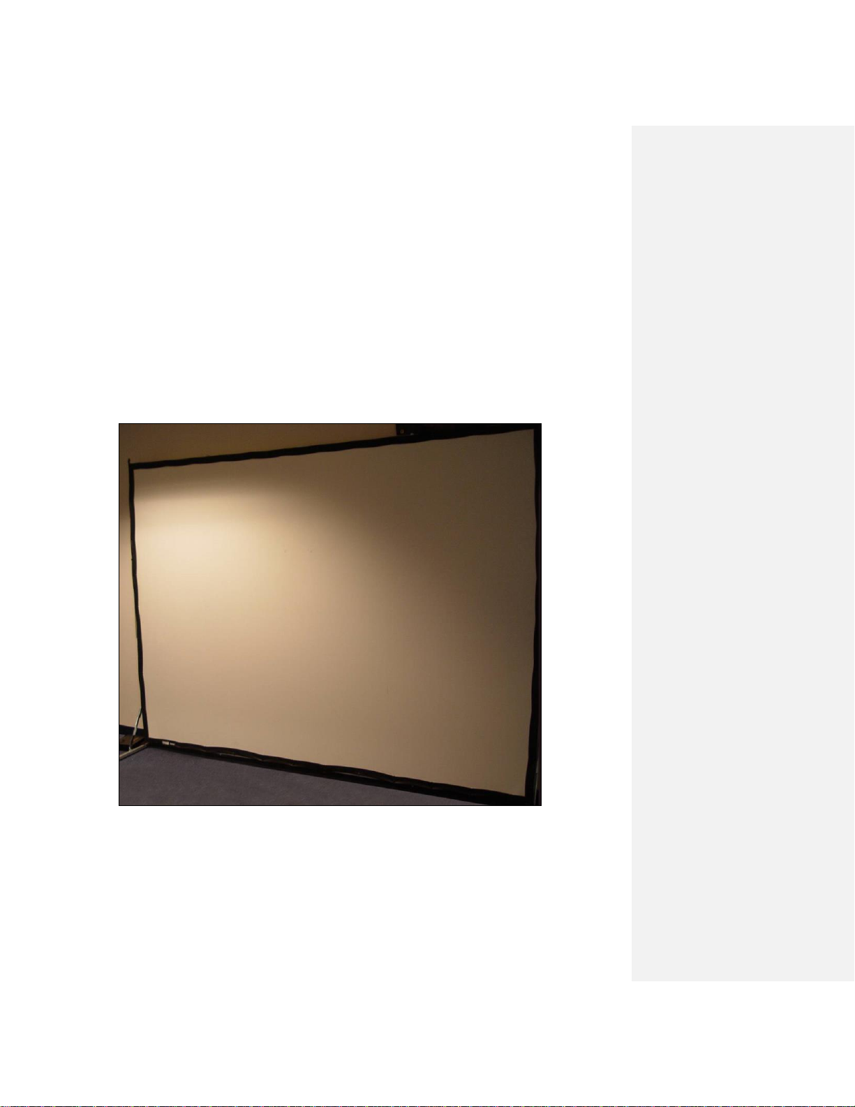
1. Assemble the projection screen and place it against a wall. Detailed instructions for screen setup
are included with the screen.

www.milorange.com
Projector Setup
NOTE: MILO Range Pro systems are generally mounted from the ceiling but also can be in a floor
mounted configuration. Both configurations are covered in the following steps
NOTE: If your system setup requires the addition of an Extron DTP DVI 330 TX and 330 Rx switch and
control please reference the Extron Set Up Guide located in the Training & Support folder either on
your desktop or C:/MILO/Training & Support/User Guides.
Floor mounted system
1. Place the projector on the floor approximately 18’ (6m) from the projection screen with the projector
lens pointed at the screen. Do not place the projector on a table or any other raised platform.
2. Connect power to the projector (Figure 1, Item 1). Make sure the cable does not interfere with the
area where the trainees will walk or stand during training.
3. Connect the HMDI cable to the HDMI #1 input (Figure 1, Item 2) on the projector. Extend the cable
to the computer location. Make sure the cable does not lie where trainees will stand during training.
4. Connect the HDMI cable to the MILO computer (Figure 2, Item 1).
HDMI atFigure 1 - PROJECTOR
Formatted Table
Comment [JP1]: Replace with current photo

www.milorange.com
DVI at COMPUTERFigure 2 – Back of Computer
Comment [JP2]: Replace with current photo

www.milorange.com
Ceiling Mounted System
1. Using the instructions provided, affix mounting hardware to projector, and construct pole ensuring
pole height with projector attached will not drop below the 9 foot recommended height of projector.
2. Install the replacement 2x2 ft. ceiling tile approximately 18 feet from the screen or surface to be
projected on.
3. Install mounting pole onto ceiling tile.
a. Ensure the safety screw on top side of ceiling tile is tightened, making firm contact with the
threads of the mounting pole
b. Attach provided safety wire from the ceiling tile to existing structure.
4. Run cables from above the ceiling, down through the mounting pole and out of the cable window
(Figure 1-4)
a. The order in which the cables should be run down the pole are as follows:
i. Power cable for projector
ii. HDMI cable
iii. 2 network cables (6 foot cables)
5. Above the ceiling, place the 8-port Gigabit switch (Figure 3, Item 1) in close proximity to the
installed MILO ceiling tile.
6. Above the ceiling, connect 2 Network cables (6 foot) to the 8-port Gigabit switch POE ports (yellow
ports) (Figure 3, Item 2).
7. Above the ceiling, connect 1 end of a 50 foot network cable to the 8-port Gigabit switch POE port
(yellow port) (Figure 3, Item 3). The other end of this cable should be run above the ceiling to the
TAC camera location.
a. This will differ if the system is in a ground mounted configuration. Refer to the TAC camera
setup portion of this manual for that connection.
8. Above the ceiling, connect 1 end of a 50 foot network cable to the 8-port Gigabit switch NON POE
port (blue port)(Figure 3, Item 4). The other end of this cable should be run above the ceiling to the
instructor station location to be connected to the MILO computer.

www.milorange.com
8. Figure 3 – 8-port Gigabit Switch
9. Above the ceiling, place a surge protector in close proximity to the installed MILO ceiling tile.
a. Plug the surge protector into an available power source. It may be necessary to use an
extension cord to facilitate this.
10. Above the ceiling, plug the power cable for the 8-port Gigabit switch into the surge protector.
11. Above the ceiling, plug the power cable for the projector into the surge protector.
12. Install the projector with mounting hardware previously installed onto the mounting pole.
a. Plug the projector power cable into the projector
b. Plug the HDMI cable into the projector
13. Install the camera tree with cameras attached to the mounting pole, ensuring the tree is aligned with
the screen and the bracket is securely fastened. (Figure 1-5)
14. Connect both Network cables to the cameras (Figure 1-6)
15.13. Above the ceiling, switch the surge protector to the ON position. Ensure the green LED light
comes on and the Gigabit switch ports that are plugged in also light up.
Trainer Station Setup
Computer Setup
1. Set computer on desired surface
2. Connect the power cable. (Figure 1-74, Item 1)
3. Connect the Network cable. (Figure 1-74, Item 2)
Formatted: PICTURE

www.milorange.com
4. Connect the 2 USB Dongles that control the keyboard and mouse. (Figure 1-74, Item 3s 3 and 4)
5. Connect the monitor DVI cable. (Figure 1-74, Item 54)
6. Connect the HDMI cable. (Figure 1-74, Item 65)
7. Connect the speaker cables. (Figure 1-74, Item 76)
8. Plug computer power cable into surge protector
8. Figure 4 – Back of computer
Monitor Setup
1. Place monitor near MILO computer
2. On back of monitor, connect the power cable. (Figure 1-8, Item 1).
3. On back of monitor, connect DVI cable. (Figure 1-8, Item 2).
Formatted: PICTURE

www.milorange.com

www.milorange.com
Formatted: Normal, Centered

www.milorange.com
Formatted: Centered
Indice