Mindman MAER210/310 Series Manuale utente

1
2022/8
SERVICE MANUAL
Electro-Pneumatic Regulater
MAER210/310 series
Order example
MAER210 – 8A – 9K – 101 – B1 S3 CS –
1
1 2
4
2 3 4 5 6 7
Port size
Communication model
Pressur display unit
10: RS-232
20: RS-485
1: MPa
2: kgf/cm2
3: bar
4: psi
5: kPa
8
3Pressure range Bracket
5
1K: 0.1 MPa
5K: 0.5 MPa
9K: 0.9 MPa
8A: 1/4
10A: 3/8
15A: 1/2
Blank: Without
B1: L type
B2: Flat type
RS-232
Power cable
6
Blank: Without
S3: Straight 3m
L3: Right angle 3m
Port thread
Blank: Rc thread
G: G thread
NPT: NPT thread
8
Commun. Cable
Blank: Without
CS: Straight 3m
CL: Right angle 3m
7
Model
210
310
2
Precaution
1Let the desingner of pneumatic system or rule tester to determine if this direction control valve
is suitable or not.
2The product must be operated by the person who has professional knowledge and practical
experience.
3Please conrm product specications before use. Do not use input signal exceeding specications.
This product could malfunction re if input signal exceeding the working range is applied.
4If an abnormality occurs during operation, immediately turn off the power and air pressure and
stop using it.
5This product is adjusted for each specication at the time of shipment from the factory.
Disassemble and reformation are prohibited, as this way might lead to malfunction.
WARNING
1Avoid using this regulator where it will be subject to direct sunlight, water or oil, etc.
2Use in place where the temperature changes drasticlly or at high humidity may cause damage
due to dew condensation in the product.
3If supply pressure to this product is interrupted while the power is still on, the inner solenoid
valve will continue to operate and a humming noise may be generated. Since the life of the
product may be shortened, shut off the power supply also when supply pressure is shut off.
4If electric power is shut off while pressure is being applied, the output pressure will be retained.
However, this output pressure is held only temporarily and is guaranteed.
To ensure safe operation, please read this service manual carefully before use. When desingning and
manufacturing equipment using Mindman products, the manufacturer isobligated to ensure that the
safety of the mechanism, pneumatic conrtol circuit and/or air control circuit and the system that runs
the electrical controls are secured.
Explanation of label
Observe the warnings and cautions on the following pages to prevent accidents. These instructions
indicate the level of potential hazard by labels of "WARNING" or "CAUTION".Note that some items
indicated with "CAUTION" may lead to serious results depending on the conditions. All items
contain important information and must be observed.
A dangerous situation may occur if handling is mistaken, leading to fatal or serious injuries.
CAUTION
A dangerous situation may occur if handling is mistaken, leading to minor injuries or property damage.
3
Precaution
5The product characteristics are conned to no ow in the pipeline. When air is consumed on
the output side, pressure may become unstable.
6In order to avoid the error caused by noise, please take the following measures:
aSet the line lter on AC power line to remove the power noise.
bKeep the product away from the engine and power line to avoid noise affects.
cInduced charge (like solenoid valve, relay), must prevent them from negative chargge.
dIn order to avoid the effects of power uctuation, please cut off the power before plug
the connector
7The cable plug is four-core wire. Please avoid contact with other wires to avoid product failure.
8Please note that the right angled cable connector does not rotate and is limited to only one
entry direction.
9Use clean compressed air that does not contain corrosive gas. Poor air quality adversely affects
function and life.
10 Do not use a lubricator on the supply side of this product, the lubricated air might cause
malfunction. When lubrication of terminal equipment is necessary, connect a lubricator on the
output side of the equipment and set a check valve.
11 When supplying compressed air for the rst time after connecting pipes, conrm that no air is
leaking from any pipe connections.
12 Tighten pipes with the appropriate torque to prevent air leakage and screw damage. First
tighten the screw by hand to prevent damage to screw threads, then use a tool.
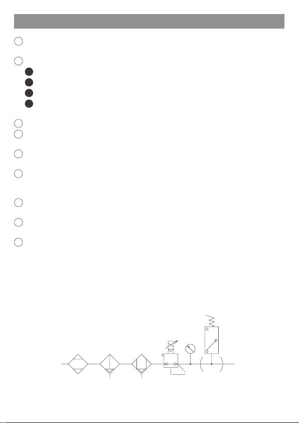
13 For the pneumatic source, use cleaned air from which the solid, water and oil contents were
eliminated sufciently, using an air dryer, lter and oil mist lter. Recommend selecting a
ltration precision of 5µm or less.
Air lter
(5µm)
Air dryer Oil/mist lter (Pressure
switch)
Regulator
4
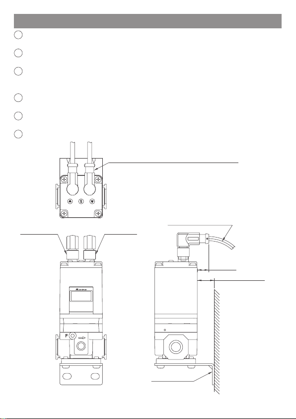
Installation instructions
1The 4-Pin port on the right side is the power supply port. Please refer to page 5 for details on
the wiring method.
2The 5-Pin port on the left side is the communication interface. Please refer to page 5 for details
on the wiring method.
3Be aware that excessive bending may cause damage or short circuit, resulting in abnormal
function or re. Be sure to reserve sufcient space for wiring. (The minimum bending radius of
the wire is 70mm)
4When installing L-type bracket and right-angle cables together with the product, pay attention
to whether the wiring space is sufcient.
5Please note that the right-angle cable connector does not rotate and is limited to only one entry
direction.
6Insert/pull out the connector after cutting the power supply.
B1: L type bracket
The right angle type cable outlet orientation is rearward.
Min. bending radius 70mm
(13.6mm)
20mm
Installation distance
Made in Taiwan
Mounting surface
Power supplyCommunication

5
Wiring method
1Please conrm the product specication and read wiring method carefully before wiring.
2The color of connector pins and cable conductors must be checked when wiring. Check wire
color with handling precaution, since improper wire connection leads to destruction/-failure
and malfunction.
3Do not use power voltage exceeding specications. The product could malfunction or catch re
if voltage exceeding the working range is applied.
4Short-circuiting the load could result in rupture or re.
5The connection between the cable plug and the wire is weak. Excessive bending may shorten
the life of the plug set, causing breakage or damage.
WARNING
Port Pin assign Wire color (*2)
Power supply
port (*1) 1
2
3
41. Power Supply Brown
2. No Connect White
3. GND Blue
4. No connect Black
Communicate
connect port 1
2
3
4
5
1. No connect Yellow
2. TxD Brown
3. RxD White
4. GND Green
5. No connect Gray
Pin assign of product connector port in RS-232 model
Connection of external equipment to RS-232 model
Communication wiring
diagram
PLC
or Pc
1: No connect
2: TxD
3: RxD
4: GND
5: No connect
Power supply wiring diagram
Power supply
DC 24V
1: Power supply
2: No connect
3: GND
4: No connect
*1. The pin-2 and pin-4 of power supper port must be prevent to connect any signal to
avoid interference or malfunction.
*2. Wire color is when the option cable is used.
*3. Please pay attention to shielding the unused pins to avoid malfunction or abnormal
function caused by noise.

6
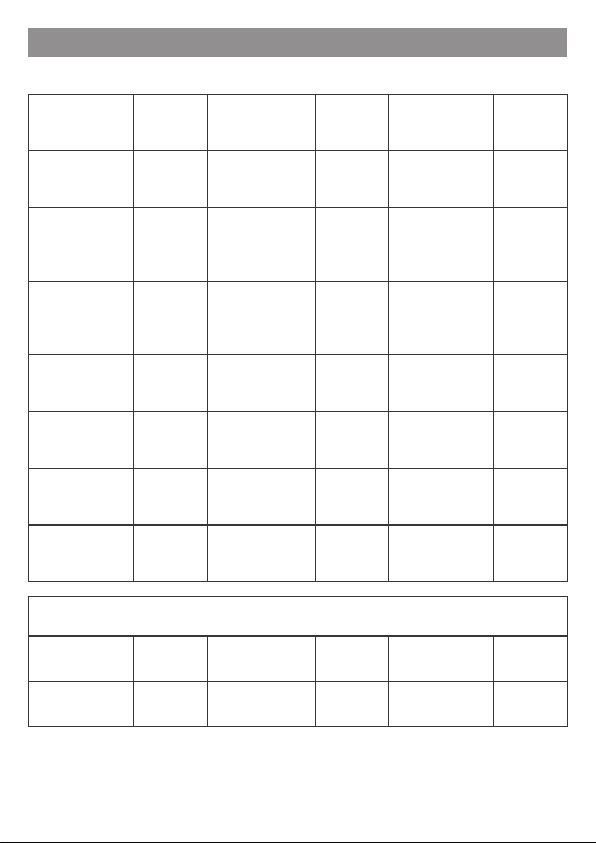
Communication specication
Item Specication
Protocol RS-232
Baud rate 19,200 bps
Transmission format setting 8,N,1
Start bit 1 bit
Data length 8 bit
Stop bit 1 bit
Parity N/A
Flow control N/A
Command end code CR/LF
Character-code ASCII
(Default)
(Default)

7
COMMUNICATION PROTOCOL
Note.
Denition Command Response Content
Read all setting data ?? … Responds to product parameter
setting values
Baud rate setting BAUD=nnnn
BAUD?
Done nnnn
nnnn nnnn=9600, 19200 or 38400
Transmission format setting PARI=ppp
PARI?
Done ppp
ppp ppp=8N1, 8E1, 8O1 or 8N2
Read current pressure NOW? AA.AA The decimal point is automatically
added according to the pressure unit
Set target pressure (*1) OBJ=BBB
OBJ?
Done BB.B
BB.B
The decimal point is automatically
added according to the pressure unit
The min. value of the set
pressure range
F1=nnnn
F1?
Done nn.nn
nn.nn
Set the min. value of the set pressure
range.
Request the min. value…
*F1: 0≤F1≤F2
The max. value of the set
pressure range
F2=nnnn
F2?
Done nn.nn
nn.nn
Set the max. value of the set pressure
range.
Request the max. value…
*F2: F1≤F2≤10.00 (@kgf/cm²)
Automatically report the
current pressure value ATUO#
#=1, 2, nothing
1: report once every 0.5 seconds
2: report once every 1.0 seconds
nothing: report once every 0.1
seconds
Stop automatically report OFF Stop automatically report function
1The character-code used to communicate is ASCII.
2Please use capital letter to command.
3Please do not put space between the command and the numerical value.
4If the command is not answered correctly, please conrm whether the content exceeds the
allowable range or undened, or check whether the communication settings are correct.
Supplement:
Set the pressure range to the values of F1 and F2. If the input exceeds the range,
UNKNOWN COMMAND will be returned.

8
COMMUNICATION PROTOCOL
Denition Command Response Content
Valve Gain Coefcient
GN=BB
GN?
Done BB
BB
Valve Gain Coefcient
Change value to increase or decrease
the pressure regulation speed.
Range: 1~26
Sensitivity
SB=BB
SB?
Done BB
BB
Sensitivity
Set pressure allowable uctuation
range.
Range: 1~16
Zero Function ZERO Done ZERO Display value set to zero.
Pressure unit setting (Unt) UNIT=sss
UNIT?
Done sss
sss sss=PSI, BAR, MPA, KGF or KPA
Air supply solenoid
valve basic duty value
UP=nnn
UP?
Done nn.n mS
nn.n mS
Set air supply solenoid valve basic
duty value.
Range: 1~255
Unit: 0.1mS
Exhaust solenoid valve basic
duty value
DN=nnn
DN?
Done nn.n mS
nn.n mS
Set exhaust solenoid valve
basic duty value.
Range: 1~255
Unit: 0.1mS
Air supply solenoid valve
additional duty value
SUP=nnn
SUP?
Done nn.n mS
nn.n mS
Set air supply solenoid valve
additional duty value.
Range: 1~255
Unit: 0.1mS
Exhaust solenoid valve
additional duty value
SDN=nnn
SDN?
Done nn.n mS
nn.n mS
Set exhaust solenoid valve
additional duty value.
Range: 1~255
Unit: 0.1mS
Frequency setting
( Self-modication is not
recommended )
FREQ=40
FREQ?
Done 40Hz
40 Hz
Set solenoid valve operating
frequency.
Range: 1~255 (Default: 40)
Unit: 1Hz
Supplement:
If the input exceeds the range, UNKNOWN COMMAND will be returned.

9
Manual operation
Unlock keys:
Press for more than 2 seconds to display Loc, and then press Sto unlock keys.
Lock keys:
Press for more than 2 seconds to display unL, and then press Sto lock keys.
Power on
Lock keys
Run mode
Unlock keys
Click S
Display
pressure
Click S
Press +
Detail Setting
Function setting
Professional setting
Sensitivity
Zero clear
Reset setting
Unit setting
Address number
Gain
Save setting
Min. pressure
Save setting
Save setting
Additional E/V Duty
Additional A/V Duty
Basic E/V Duty
Basic A/V Duty
Max. pressure
Baud rate setting
Transmission format
Click
Display
unit
Over 2 sec
Press S
Over 2 sec
A/V: Air supply solenoid valve ; E/V: Exhaust solenoid valve.
Flow chart
10
MPa APA kgf/cm2 89F bar BAR
psi P5; kPa 8PA
Pressure display unit
Display character and function comparison table
Valve Gain
Coefcient
(GN)
GN Min. value of the
set pressure range F=1 Air supply
solenoid valve
basic duty
vp
Sensitivity
(SB) 5B Max. value of the
set pressure range F=2 Exhaust solenoid
valve basic duty
value
dn
Zero Function
(ZERO) -0- Switch output
point 1 P=1
Air supply
solenoid valve
additional duty
value
5VP
Reset setting
(RESET) r5t Switch output
point 2 P=2 Exhaust solenoid
valve additional
duty value
5DN
Unit setting unt Switch output TR; Save setting 5AU
Address
number adr Hysteresis mode KY5
Baud rate setting 8vd Window
comparator mode !;N
Trans. Format par
Note: The Address number setting is nonfunctional in RS-232 type.
Indice
Altri manuali Mindman Controllori


