Minebea Intec PR 6012/02 Manuale utente
Maxi FLEX and Maxi FLEXLOCK mounting kits PR 6012/02, ../32, ../42
Installation Manual
Translation of the Original Installation Manual 9499 053 24200 Edition 1.5.0 06/01/2020
Minebea Intec GmbH, Meiendorfer Str. 205 A, 22145 Hamburg, Germany
Phone: +49.40.67960.303 Fax: +49.40.67960.383

Foreword
Must be followed!
Any information in this document is subject to change without notice and does not represent a commitment on
the part of Minebea Intec unless legally prescribed. This product should only be operated/installed by trained
and qualied personnel. In correspondence concerning this product, the type, name, and release number/serial
number as well as all license numbers relating to the product have to be cited.
Note
This document is partially protected by copyright. It may not be changed or copied, and it may not be used
without purchasing or written permission from the copyright owner (Minebea Intec). The use of this product
constitutes acceptance by you of the abovementioned provisions.

Table of contents
1 Introduction......................................................................................................................................... 3
1.1 Read the manual.........................................................................................................................................................3
1.2 This is what operating instructions look like..........................................................................................................3
1.3 This is what lists look like...........................................................................................................................................3
1.4 This is what menu items and softkeys look like.....................................................................................................3
1.5 This is what the safety instructions look like.......................................................................................................... 3
1.6 Hotline..........................................................................................................................................................................4
2 Safety instructions...............................................................................................................................5
2.1 General notes..............................................................................................................................................................5
2.2 Intended use................................................................................................................................................................5
2.3 Initial inspection..........................................................................................................................................................5
2.4 Before operational startup........................................................................................................................................5
3 Recommendations for installation .......................................................................................................6
3.1 Load cell and constrainer arrangement..................................................................................................................6
3.2 Mounting aid............................................................................................................................................................... 7
3.3 Internal lift-o protection with integrated jack-up ..............................................................................................8
3.3.1 General instructions ........................................................................................................................................8
3.3.2 Jack-up..............................................................................................................................................................9
3.3.3 Adjusting the built-in lift-o protection.................................................................................................... 10
3.4 Additional lift-o protection ................................................................................................................................... 11
4 Specications .....................................................................................................................................12
4.1 Equipment supplied..................................................................................................................................................12
4.1.1 Maxi FLEX mounting kit PR 6012/02N and PR 6012/02S........................................................................12
4.1.2 Maxi FLEXLOCK PR 6012/32N and PR 6012/32S.......................................................................................13
4.1.3 Maxi FLEXLOCK PR 6012/42N and PR 6012/42S ..................................................................................... 14
4.2 Dimensions.................................................................................................................................................................15
4.3 Technical data ............................................................................................................................................................17
5 Installation......................................................................................................................................... 19
5.1 Prior to mounting ..................................................................................................................................................... 19
5.1.1 Preparing the foundation/substructure .................................................................................................... 19
5.2 Tightening torques...................................................................................................................................................20
5.3 Assembly....................................................................................................................................................................20
5.3.1 Safety instructions.........................................................................................................................................20
5.3.2 Installing the mounting kit and inserting the load cell.............................................................................21
5.4 Check mounting........................................................................................................................................................24
6 Cleaning.............................................................................................................................................25
Maxi FLEX and Maxi FLEXLOCK mounting kits PR 6012/02, ../32, ../42 Table of contents
Minebea Intec EN-1

7 Disposal .............................................................................................................................................26
8 Spare parts and options ..................................................................................................................... 27
8.1 Replacement parts ...................................................................................................................................................27
8.2 Options.......................................................................................................................................................................27
8.2.1 Lift-o protection..........................................................................................................................................27
Maxi FLEX and Maxi FLEXLOCK mounting kits PR 6012/02, ../32, ../42 Table of contents
EN-2 Minebea Intec

1 Introduction
1.1 Read the manual
-Please read this manual carefully and completely before using the product.
-This manual is part of the product. Keep it in a safe and easily accessible location.
1.2 This is what operating instructions look like
1. - n. are placed before steps that must be done in sequence.
1.3 This is what lists look like
-indicates an item in a list.
1.4 This is what menu items and softkeys look like
[ ] frame menu items and softkeys.
Example:
[Start]- [Applications]- [Excel]
1.5 This is what the safety instructions look like
Signal words indicate the severity of the danger involved when measures for preventing
hazards are not followed.
DANGER
Warning of personal injury
DANGER indicates death or severe, irreversible personal injury which will occur if the
corresponding safety measures are not observed.
Take the corresponding safety precautions.
WARNING
Warning of hazardous area and/or personal injury
WARNING indicates that death or severe, irreversible injury may occur if appropriate
safety measures are not observed.
Take the corresponding safety precautions.
CAUTION
Warning of personal injury.
CAUTION indicates that minor, reversible injury may occur if appropriate safety
measures are not observed.
Take the corresponding safety precautions.
is placed before a step.
describes the result of a step.
1 Introduction Maxi FLEX and Maxi FLEXLOCK mounting kits PR 6012/02, ../32, ../42
Minebea Intec EN-3

NOTICE
Warning of damage to property and/or the environment.
NOTICE indicates that damage to property and/or the environment may occur if
appropriate safety measures are not observed.
Take the corresponding safety precautions.
Note:
User tips, useful information, and notes.
1.6 Hotline
Phone: +49.40.67960.444
Fax: +49.40.67960.474
eMail: [email protected]
Maxi FLEX and Maxi FLEXLOCK mounting kits PR 6012/02, ../32, ../42 1 Introduction
EN-4 Minebea Intec

2 Safety instructions
2.1 General notes
NOTICE
Warning of damage to property and/or the environment.
The product was in perfect condition with regard to safety features when it left the
factory.
To maintain this condition and to ensure safe operation, the user must follow the
instructions and observe the warnings in this manual.
2.2 Intended use
The mounting kits PR 6012/02, ../32, ../42 are intended for weighing tasks, and must only
be used as such.
The mounting kits PR 6012/02, ../32, ../42 are designed for installing the load
cells PR 6212 (500 kg–10 t).
The dimensions of all mounting and structural components must be calculated so that
sucient overload capacity is ensured for all loads which may occur while taking the
relevant standards into account. In particular, upright weighing objects must be
safeguarded against the weighing installation turning over or being shifted, thus
eliminating danger to people, animals, or goods even in the case of a break in a load cell
or mounting element.
Installation and repair work must only be carried out by expert/qualied personnel.
The mounting kits reect the state of the art. The manufacturer does not accept any
liability for damage caused by third-party system components or due to incorrect use of
the product.
2.3 Initial inspection
Check the contents of the consignment for completeness. Check the contents visually to
determine whether any damage has occurred during transport. If there are grounds for
rejection of the goods, a claim must be led with the carrier immediately. The
Minebea Intec sales or service organization must also be notied.
2.4 Before operational startup
NOTICE
Perform visual inspection.
Before operational startup as well as after storage or transport, inspect the
mounting kit visually for signs of mechanical damage.
2 Safety instructions Maxi FLEX and Maxi FLEXLOCK mounting kits PR 6012/02, ../32, ../42
Minebea Intec EN-5
3 Recommendations for installation
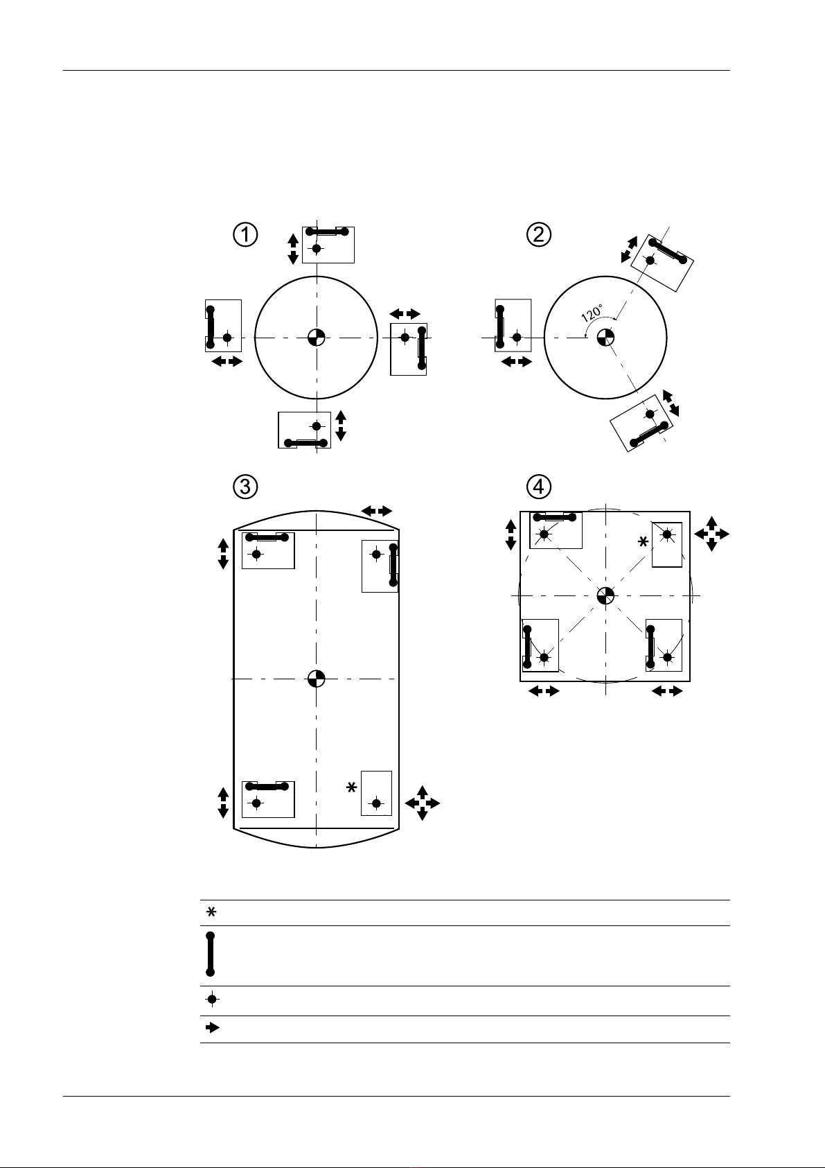
3.1 Load cell and constrainer arrangement
Examples:
Key
Do not constrain this position.
Constrainer
Load application
Possible direction of movement
Maxi FLEX and Maxi FLEXLOCK mounting kits PR 6012/02, ../32, ../42 3 Recommendations for installation
EN-6 Minebea Intec
-To ensure the required free moving space of the weighing facility, a maximum of
3 mounting kits with constrainer may be used to constrain a weighing object.
Round containers are the exception (image ① and ②). In this case, any number of
constrainers can be installed, provided that they are tangentially aligned.
Special mounting kits are available for weighing points without constrainers.
Alternatively, the constrainer can simply be removed.
With elastic constructions, it may be necessary to deviate from this recommendation
in order to guarantee the weighing object has sucient stability.
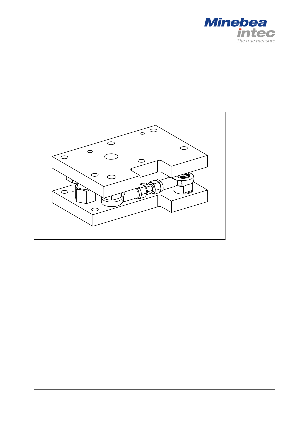
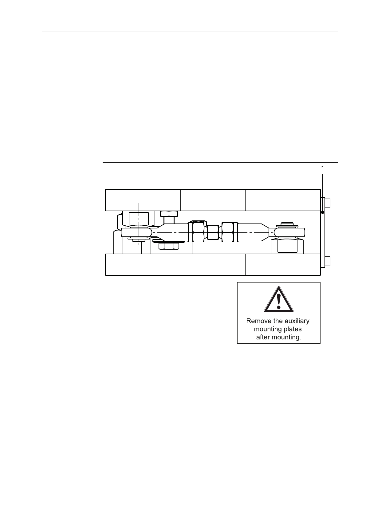
3.2 Mounting aid
Example: PR 6012/32
The auxiliary mounting plate (1) is intended to facilitate installation of the mounting kit
and load cell.
3 Recommendations for installation Maxi FLEX and Maxi FLEXLOCK mounting kits PR 6012/02, ../32, ../42
Minebea Intec EN-7
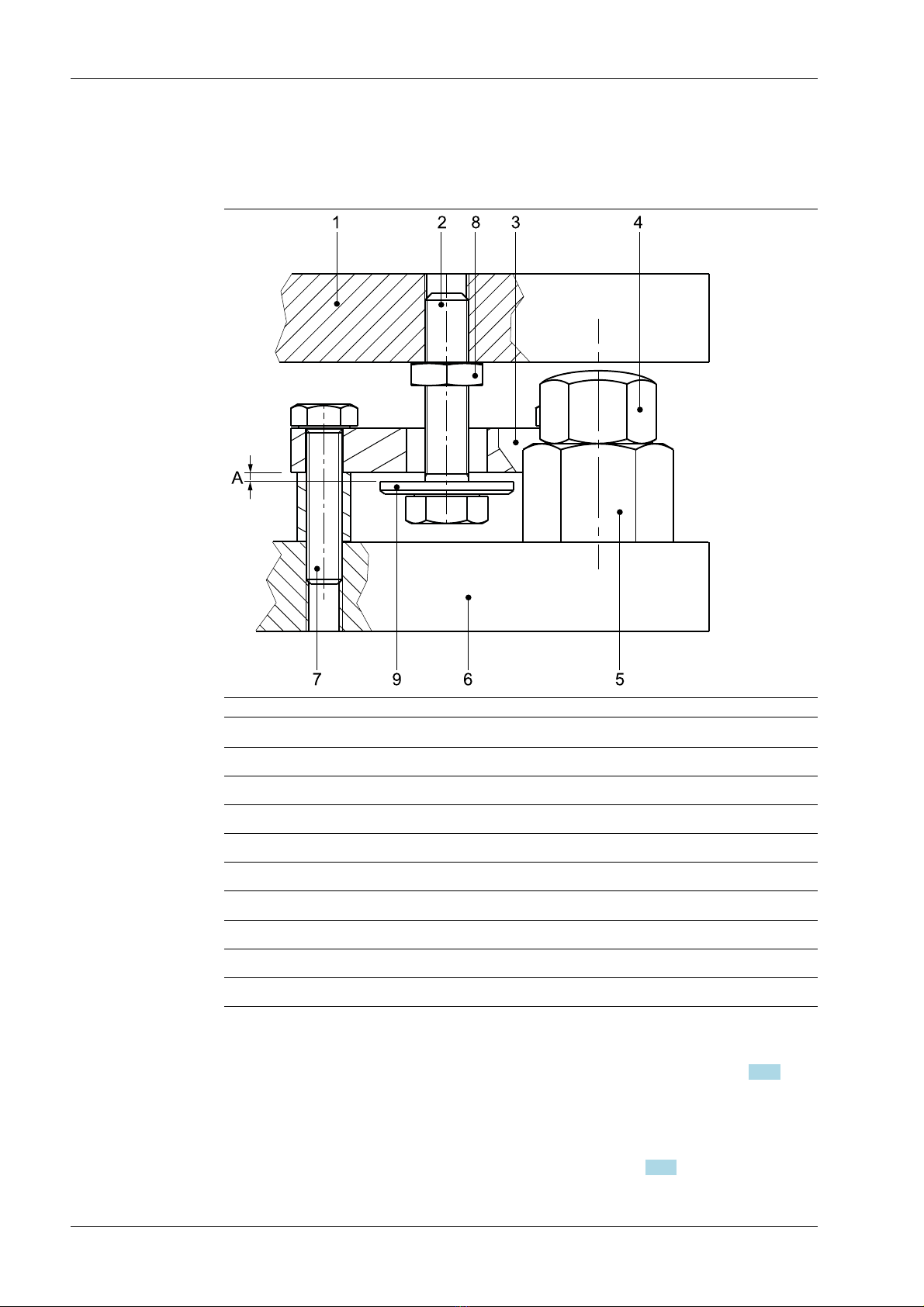
3.3 Internal lift-o protection with integrated jack-up
3.3.1 General instructions
No. Description
1 Upper plate
2 Screw
3 Retaining plate
4 Threaded bolt
5 Threaded bush
6 Lower plate
7 Screw (2×)
8 Nut
9 Washer
The mounting kits are equipped with an internal lift-o protection, i.e. no additional
borings apart from the mounting holes in the vessel foot are required.
Moreover, the vessel can be lifted by turning the threaded bolt (4) (see Chapter 3.3.2),
e.g., when inserting the load cell.
The two screws (7) are screwed into the lower plate (6).
The screw (2) is screwed into the upper plate (1) and locked with the nut (8).
That way, the safety clearance "A" can be adjusted (see Chapter 3.3.3).
Maxi FLEX and Maxi FLEXLOCK mounting kits PR 6012/02, ../32, ../42 3 Recommendations for installation
EN-8 Minebea Intec
Questo manuale è adatto per i seguenti modelli
7
Indice
Altri manuali Minebea Intec Rack e supporto

Minebea Intec
Minebea Intec Mini FLEXLOCK Manuale utente

Minebea Intec
Minebea Intec PR 92/00N Manuale utente

Minebea Intec
Minebea Intec PR 6021 Manuale utente

Minebea Intec
Minebea Intec PR 95T/00S Manuale utente

Minebea Intec
Minebea Intec PR 97/00 Series Manuale utente

Minebea Intec
Minebea Intec Maxi FLEXLOCK Manuale utente

Minebea Intec
Minebea Intec PR 6144 Series Manuale utente

Minebea Intec
Minebea Intec PR 6011/00S Manuale utente

Minebea Intec
Minebea Intec PR 6041/30 Manuale utente


