Model Train Technology Signal Controller Manuale utente

April 2021
1
Signal Controller™
OPERATIONS MANUAL
Version 1.1b
April 2021
2

April 2021
3
INTRODUCTION
The Model Train Technology™ Signal Controller™ provides an
extremely simple plug-and-play system for lighting and
animating layout block signals and RR Crossing Flashers.
After years of running block signaling from the computer via
train software, I decided that for my 4x8’ demo layout I
wanted a very simple system that gives the appearance of a
much more sophisticated operation – without all the work.
And I wanted a lot less wiring.
Our simplified system will provide great animation in just a
few minutes of installation time, not days or years and at a
fraction of the cost of elaborate CTC systems. And frankly,
very few if any of the visitors to your layout will know the
difference!

April 2021
4
OVERVIEW
Each MTT Signal Controller (“Controller”) stands on its own
and is triggered by a sensor, either under the track or
mounted on the side of the track. Our Precision Detector™ is a
great choice since it is not based on IR (infrared) and is
therefore not impacted by difficult lighting conditions. The
Controller has an optional magnetic base and can be easily
mounted upside-down under the layout so that the Controller
can be removed easily when needed.
The Controller also has a built in DCC decoder that will allow
your block signals change automatically when you switch a
turnout or route. No software, computer or programming is
necessary. And there is no complicated wiring.
When the Controller is tripped by a sensor it starts a display
(aspect) cycle that begins with red. While the sensor shows
occupied, the Controller will stay red. Once the block is
cleared the Controller will start a change of light sequence
based on one of the options shown below. The time between
stages can be adjusted on the Controller.

April 2021
5
The Controller has three outputs that are synchronized to a
behavior. You can adjust the brightness of each of the output
individually. This lets you set the brightness appropriate to
your layout. You can also individually adjust each of the
different colored LEDS. The typical colors of the LEDS (Red,
Yellow and Green) do not glow at the same brightness with
the same voltage. The Controller allows you to adjust them to
your liking. No resistors are needed!
The Controller allows you to set the speed by which Aspect
(colors) shift from Red to Yellow to Green after the train has
passed and the block is unoccupied. You can make it occur
almost immediately, or you can set it up to 30 seconds. Each
Controller has its own speed adjustment
The Controller has eight distinct behaviors that are set with
the single push button. The time between stages is set with
the screwdriver(provided) and trim screw. They are:
• Red, Green
• Red, Yellow, Green
• Red, Yellow, Yellow flash, Green
• R, R&Y, G&Y, Green
• R, R&Y, R&Y-Flash, G&Y-flash, Green

April 2021
6
• Red, fade to Yellow, fade to Green
• Alternate flash Red & Green (speed adjustable) *
• Alternate flash R & G with fade (speed adjustable) *
*For use with gate crossings.
There are two types of controller. One type is for LEDs and
the other is for Fiber Cable lit block signals. Functionally, they
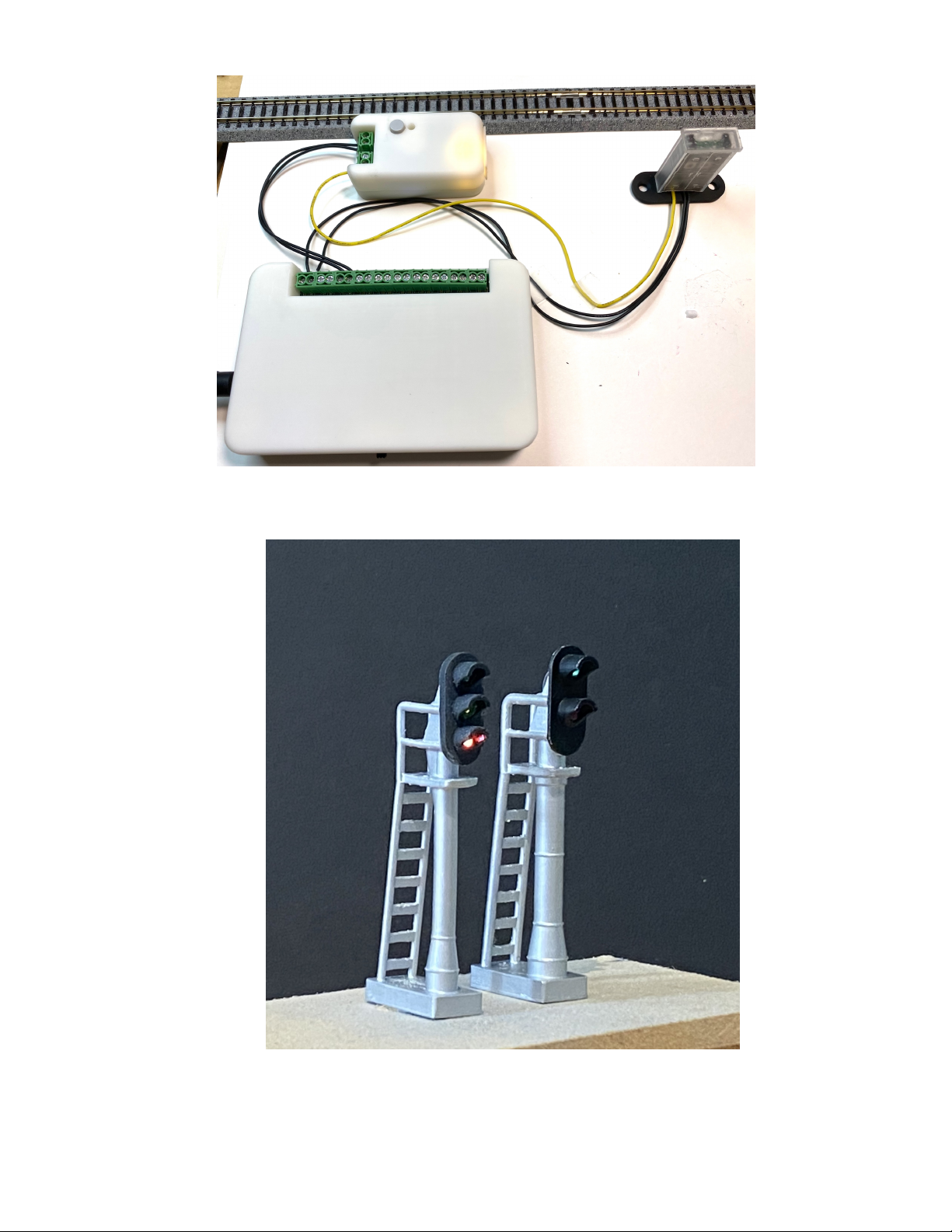
operate identically. Shown on page 11 is our MTT Power
Module and our Precision Detector™ connected to the
Controller. Two wires power the Controller and a single
trigger wire connects the detector to the Controller.
The Controller can light two LED block signals each with three
2-5v LEDS. The Fiber version normally will light a single block
signal in HO, but you can put two N Scale .50mm fibers into a
special two-cable fiber pin. Thus, you can have two 3-light N
scale fiber signal block controlled by a single controller. Fiber
block signals lights are available in O/S with an G scale version
available soon.
April 2021
7
SETUP AND OPERATION
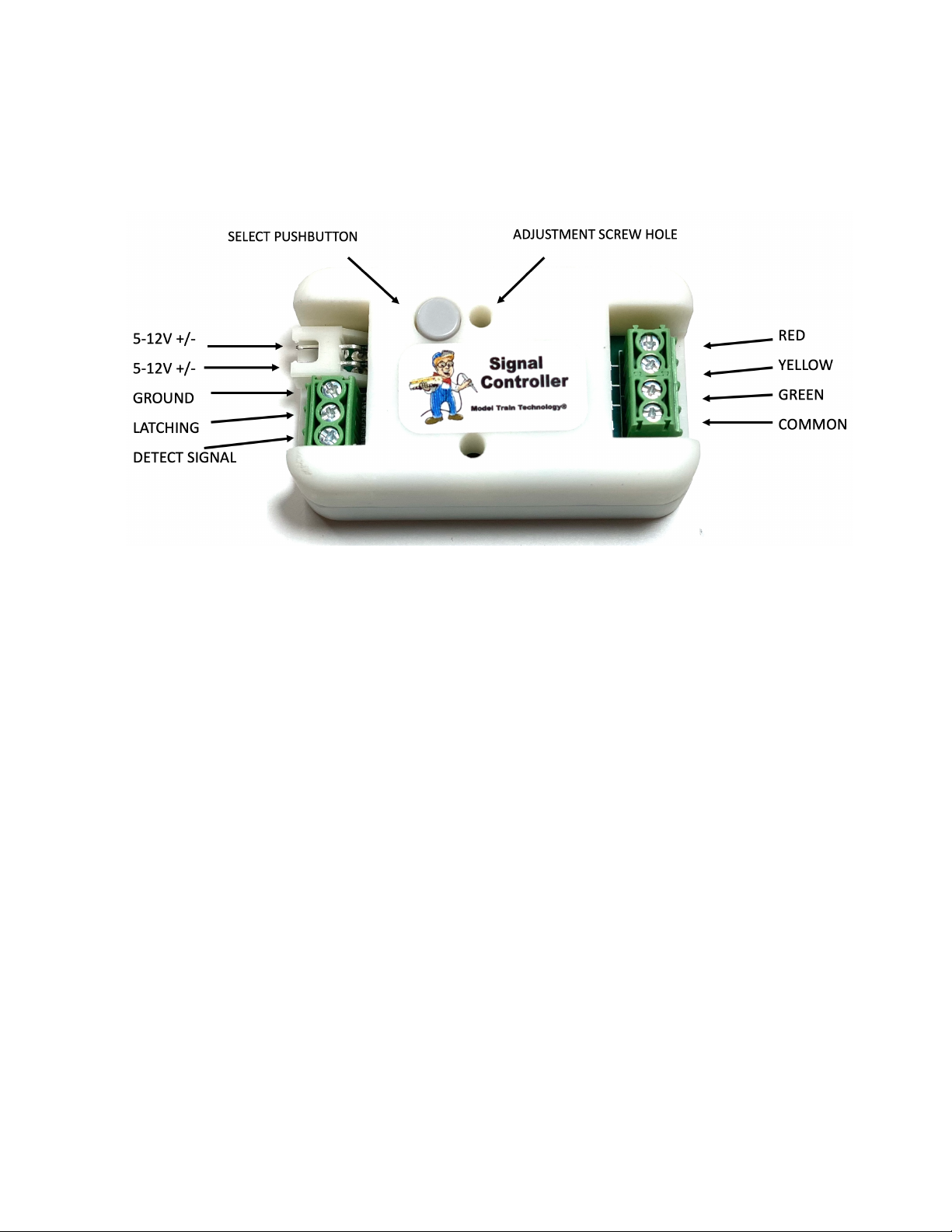
The Controller setup is simple. Connect to a 5-12VDC power source
(or DCC power) to the topmost JST terminals as shown above.
Connect your Signal LEDs as shown on the right. The LEDs can be
common Cathode or Common Anode. Common Cathode means the
COMMON is negative (usually the black wire, but not always).
Common Anode means the COMMON is VCC+, or POSITIVE voltages
and usually a red wire.
The Detect Signal input is an OPEN DRAIN (GROUND) connection.
That means that the signal it’s looking for is a digital LOW.
If you use our MTT Power Module to power your detectors and the
Controller you only need the single yellow SIGNAL wire to connect the
trigger wire.

April 2021
8
If you have another kind of sensor system you can either have them
share the same power supply or use the GROUND terminal. You may
also “short” the ground and the signal to create the same result. In
other words, a simple mechanical switch between SIGNAL and
GROUND will trip the Controller. Very simple.
SELECTING A SIGNAL BEHAVIOR (ASPECTS)
You push the pushbutton the number times need to select and option
according to the table below. Once you stop pushing the button the
Controller will wait 2 seconds and then all the LEDs will turn off. One
second later the green signal LED will blink the number count
matching the button pushes, except for one button push which is the
brightness adjustment mode.
PUSHES
SIGNAL BEHAVIOR
2
Red, Green
3
Red, Yellow, Green
4
Red, Yellow, Yellow flash, Green
5
R, R&Y, G&Y, Green
6
R, R&Y, R&Y-Flash, G&Y-flash, Green
7
Red, fade to Yellow, fade to Green
8
Alternate flash Red & Green (speed adjustable) *
9
Alternate flash R & G with fade (speed adjustable) *
The default setting is 3.

April 2021
9
SELECTING THE BEHAVIOR SPEED
The behavior speed adjustment screw is inside the Controller. You
access it with the provided 2mm screwdriver. Gently turn the screw
inside from zero to about 300 degrees. It does not turn 360 degrees.
Left or counterclockwise is faster (less time between stages), right or
clockwise increases the time between stages. You can make the
adjustment at any time since the Controller reads the setting at the
beginning of each detector trip event.
SETTING THE BIGHTNESS (LED & FIBER)
Setting the brightness for each output is accomplished through a
series of SINGLE pushes to the select button. In an idle state, with no
triggers active, press the select button once. This will START the
sequence to adjust ALL the LED outputs one at a time.
After the first press all the LEDs will light, and the RED led will be
active for the adjustment. You may not see any visible change.
Gently Insert the screwdriver into the adjustment screw hole and turn
the insider screw clockwise and counterclockwise to reach the desired
brightness for the red LED.
When you are happy with the setting, press the select button - once.
This will save the Red LED setting; the Red LED will blink and cycle the
adjustment to the Yellow LED. Adjust as needed. Then press the
button once again. The Yellow LED will blink and then set the mode

April 2021
10
for adjustment to the Green LED. Once you are set with the Green
LED brightness setting, press the select button one final time.
After the final press, all three LEDs will flash and turn off. After that
and depending on the behavior setting, one of two things will happen:
1. If you have set behavior between 2 and 7, the Green LED will light,
and the system will be ready to receive a Block Occupied trip signal.
2. If you have selected either behavior 8 or 9, which are the crossing
gate alternate flash modes, all the LEDs will remain off until a block
occupied trip signal is received.
NOTE: after you have adjusted the brightness, remember to RE-SET
the adjustment screw to the timeout setting you want. Most of the
time when you set the brightness of the LEDs the adjustment screw
will be toward the “high” side, meaning all the way clockwise. This
is also the LONGER time setting for the aspect changes.
Indice
Altri manuali Model Train Technology Giocattolo


