MOGlabs MFE Manuale utente
Fibre Amplifier
MFE
Revision 1.02

Limitation of Liability
MOG Laboratories Pty Ltd (MOGLabs) does not assume any liabil-
ity arising out of the use of the information contained within this
manual. This document may contain or reference information and
products protected by copyrights or patents and does not convey
any license under the patent rights of MOGLabs, nor the rights of
others. MOGLabs will not be liable for any defect in hardware or
software or loss or inadequacy of data of any kind, or for any direct,
indirect, incidental, or consequential damages in connections with
or arising out of the performance or use of any of its products. The
foregoing limitation of liability shall be equally applicable to any
service provided by MOGLabs.
Copyright
Copyright ©MOG Laboratories Pty Ltd (MOGLabs) 2016 – 2022.
No part of this publication may be reproduced, stored in a retrieval
system, or transmitted, in any form or by any means, electronic,
mechanical, photocopying or otherwise, without the prior written
permission of MOGLabs.
Contact
For further information, please contact:
MOG Laboratories P/L
49 University St
Carlton VIC 3053
AUSTRALIA
+61 3 9939 0677
MOGLabs USA LLC
419 14th St
Huntingdon PA 16652
USA
+1 814 251 4363
www.moglabs.com

Preface
The MOGLabs MFE Fibre Amplifier is a modular system based on
Er and Yb doped active fibres. Internal modules can include seed
and up to three stages of amplification, from 500 mW to 20 W. Wave-
lengths extend from 1000 to 1100 nm and 1530 to 1610 nm. It can
be operated via front-panel controls, or using a computer communi-
cations interface (TCP/IP or USB) with simple text-based commands.
We hope that the MFE meets and exceeds your expectations. Please
let us know if you have any suggestions for improvement in the MFE
or in this document, and check our website from time to time for
updated information.
MOGLabs www.moglabs.com
i

ii

Safety Precautions
Safe and effective use of this product is very important. Please read
the following safety information before attempting to operate your
laser. Also please note several specific and unusual cautionary notes
before using the MOGLabs MFE, in addition to the safety precautions
that are standard for any electronic equipment or for laser-related
instrumentation.
CAUTION – USE OF CONTROLS OR ADJUSTMENTS OR
PERFORMANCE OF PROCEDURES OTHER THAN THOSE
SPECIFIED HEREIN MAY RESULT IN HAZARDOUS
RADIATION EXPOSURE
Laser output can be dangerous. Please ensure that you implement
the appropriate hazard minimisations for your environment, such as
laser safety goggles, beam blocks, and door interlocks. MOGLabs
takes no responsibility for safe configuration and use of your laser.
Please:
•Avoid direct exposure to the beam.
•Avoid looking directly into the beam.
•Note the safety labels and heed their warnings.
•When the laser is switched on, there will be a short delay of
two seconds before the emission of laser radiation, mandated
by European laser safety regulations (IEC 60825-1).
•The STANDBY/RUN keyswitch must be turned to RUN before
the laser can be switched on. The laser will not operate if
the keyswitch is in the STANDBY position. The key cannot be
iii

iv
removed from the controller when it is in the clockwise (RUN)
position.
•To completely shut off power to the unit, turn the keyswitch
anti-clockwise (STANDBY position), switch the mains power
switch at rear of unit to OFF, and unplug the unit.
•When the STANDBY/RUN keyswitch is on STANDBY, there can-
not be power to the laser diode, but power can still be supplied
to the laser head for temperature control.
CAUTION The supply must include a good ground connection.
CAUTION To ensure correct cooling airflow, the unit should not be oper-
ated with cover removed.
WARNING The internal circuit boards and many of the mounted compo-
nents are at high voltage, with exposed conductors, in particu-
lar mains supply to various sections of the power supply. The
unit should not be operated with cover removed.
NOTE The MOGLabs MFE is designed for use in scientific research
laboratories. It should not be used for consumer or medical
applications.
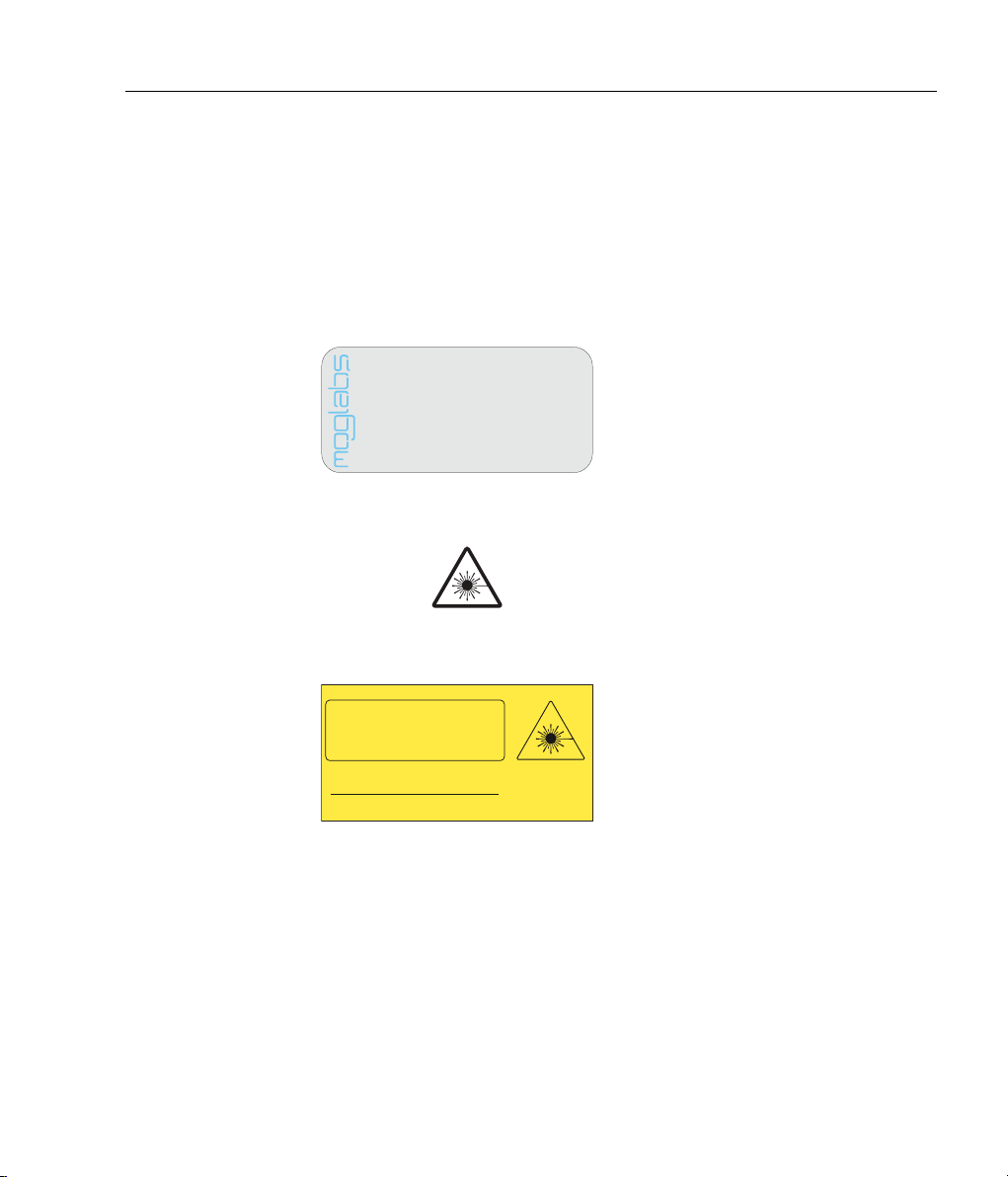
Label identification
The International Electrotechnical Commission laser safety standard
IEC 60825-1:2007 mandates warning labels that provide information
on the wavelength and power of emitted laser radiation, and which
show the aperture where laser radiation is emitted. Figures 1 and
2 show examples of these labels and their location on the device.
v
Emission connector symbol
US FDA compliance
Warning and advisory label
Class 4
Model number: MFE
Serial number: A82108001
Manufactured: AUGUST 2021
Complies with21CFR1040.10,and1040.11 except for
deviations pursuant to Laser NoticeNo.50,dated 24June2007
MOG LaboratoriesPty Ltd, 49 University St
Carlton VIC 3053, AUSTRALIA
IEC 60825-1:2007
AS/NZS 2211.5:2006
INVISIBLE LASER RADIATION
AVOID EYE OR SKIN EXPOSURE TO
DIRECT OR SCATTERED RADIATION
CLASS 4 LASER PRODUCT
Wavelength Max Power
1050nm 5W
LASER RADIATION
Figure 1: US FDA compliance and laser warning advisory labels.
vi
IEC 60825-1:2007
AS/NZS 2211.5:2006
INVISIBLE LASER RADIATION
AVOID EYE OR SKIN EXPOSURETO
DIRECT OR SCATTERED RADIATION
CLASS 4 LASER PRODUCT
Wavelength Max Power
1050nm 5W
Laser warning advisor
Model number: MFE
Serial number: A82108001
Manufactured: AUGUST 2021
Complieswith 21 CFR1040.10,and 1040.11 except for
deviations pursuant to Laser NoticeNo.50,dated 24 June2007
MOG LaboratoriesPty Ltd, 49 University St
Carlton VIC 3053, AUSTRALIA
FDA compliance
and serial number
Model number:
MFE
Serial number:
A82108001
Manufactured:
AUGUST 2021
Complieswith21 CFR1040.10,and1040.11 except for
deviationspursuant to Laser NoticeNo.50, dated24 June2007
MOGLaboratories Pty Ltd, 49 University St
Carlton VIC 3053, AUSTRALIA
IEC60825-1:2007
AS/NZS2211.5:2006
INVISIBLELASER RADIATION
AVOIDEYE OR SKIN EXPOSURETO
DIRECTOR SCATTERED RADIATION
CLASS4 LASER PRODUCT
Wavelength MaxPower
1050nm 5W
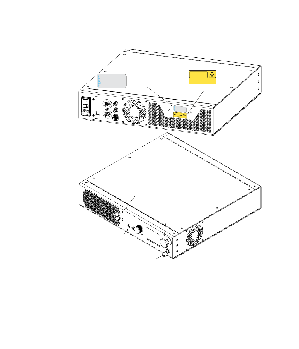
Emission indicator
Laser emission
Fibre FC connector
Keyswitch
Emergency off
switch
Figure 2: Schematic showing location of warning labels compliant with In-
ternational Electrotechnical Commission standard IEC 60825-1:2007, and
US FDA compliance label. Warning advisory label and compliance label
are on the rear panel. Emission is from the front panel FC fibre connector
labelled with triangular laser radiation symbol. Emission indicator is la-
belled AMP. Safety keyswitch and emergency off switch are also indicated.

Protection Features
The MOGLabs MFE includes a number of features to protect you and
your laser.
Softstart A time delay (3 s) followed by linearly ramping the pump diode
current (1 s/A max).
Circuit shutdown Many areas of the circuitry are powered down when not in
use. The pump diode current supplies may be without power
when the unit is in standby mode, if an interlock is open, or a
fault condition is detected.
Current limit Sets a maximum possible pump diode injection current (one
per stage).
Cable continuity If the pump diode fail and become open- or short-circuit, the
system will switch to standby and disable all laser supplies.
Short circuit If the pump diode fail and become short-circuit, it will be dis-
abled accordingly.
Temperature If the detected temperature is outside normal operating tem-
perature, the amplifier is disabled.
Internal supplies If the internal DC power supply (+24 V) is 4 V or more below
its nominal value, the respective components are disabled.
Emergency stop button In the case of emergency the entire system can be turned off
by pushing the emergency stop button on the front panel. This
will break the connection with mains power.
vii

viii
Emission indicator The MOGLabs controller will illuminate the current warning
indicator LED immediately when the amplifier is switched on.
There will then be a delay of at least 3 seconds before actual
laser emission.
Mains filter Protection against mains voltage supply transient peaks.
Key-operated The amplifier cannot be powered unless the key-operated STANDBY
switch is in the RUN position, to protect against unauthorised
or accidental use. The key cannot be removed from the con-
troller when it is in the clockwise (RUN) position.
Interlocks The main unit has an external interlock to allow the amplifier
to be disabled via a remote switch.
Seed input A photodetector in the amplifier is used to detect the presence
of seed laser input. The amplifier will not start unless there
is sufficient input seed power.
Indice


