montwill M1 Manuale utente

Technical features:
• red display of -1999…9999 digits (optional: green, orange or blue display)
• minimal installation depth: 25 mm without plug-in terminal
• adjustment via factory default or directly on the sensor signal
• min/max-memory
• displayed in °C/°F
• display flashing at threshold exceedance / undershooting
• impedance matching
• programming interlock via access code
• protection class IP65 at the front
• plug-in terminal
• pc-based configuration software PM-TOOL with CD and USB-adapter for
devices without keypad for a simple adjustment of standard devices
User Manual M1
96x48M1_1C6GB.pdf update: 27.05.2020
Pt1000 2-wire -200…850°C / -328…1562°F

Identification
Please state physical unit by order, e.g. °C
STANDARD TYPES ORDER NUMBER
Pt1000 2-wire
Housing size: 96x48 mm
M1-1TR4B.030C.570xD
M1-1TR4B.030C.770xD
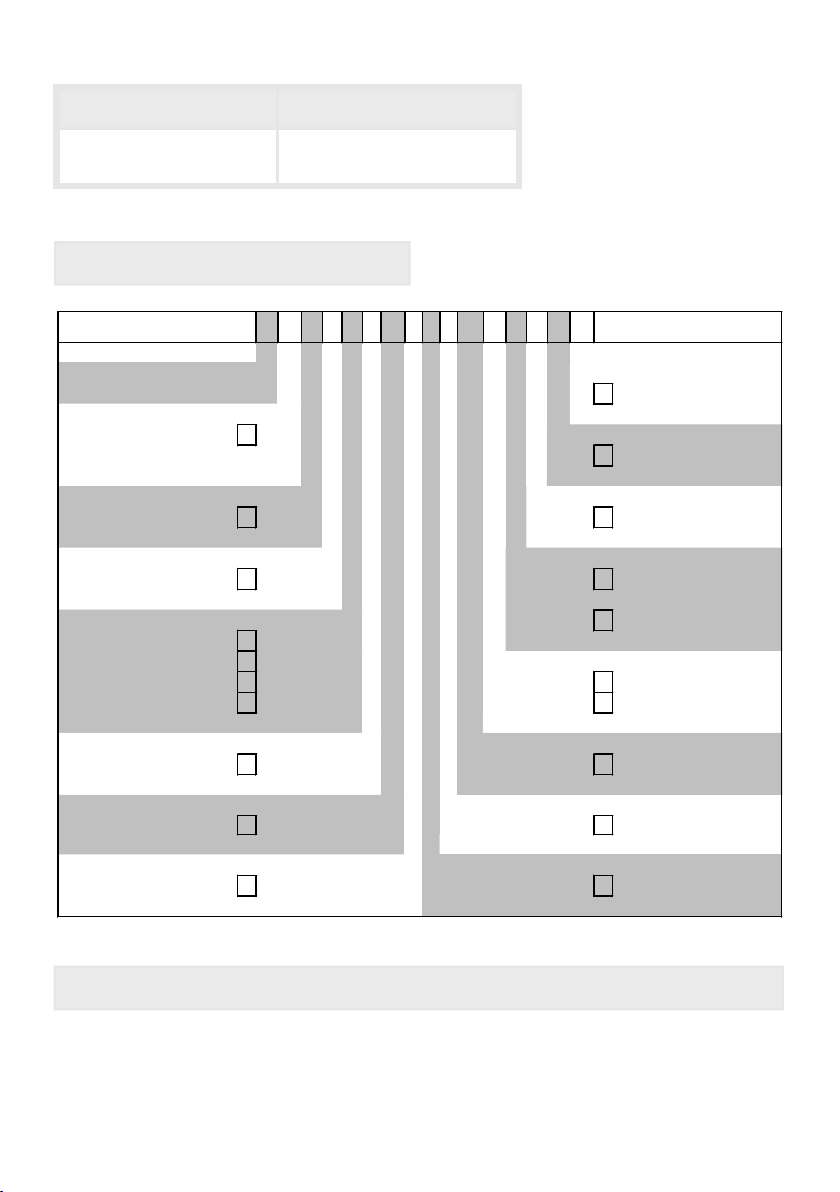
Options – breakdown of order code:
M 1- 1 T R 4 B. 0 6 0 C. 7 7 0 x D
Basic type M-Line Dimension
D physical Unit
Installation depth
38 mm 1 Version
incl. plug-in terminal x internal version
Housing size Switching points
96x48x25 mm (WxHxD) 1 0 no switching points
Display type Protection class
Temperature T 1 without keypad,
operation via PM-TOOL
Display colours 7 IP65/plug-in terminal
Blue B
Green G Supply voltage
Red R 5 230 VAC
Orange Y 7 24 VDC galv. isolated
Number of digits Measuring input
4-digit 4 C Pt1000
Digit height Analog output
14 mm
B
0
Without
Interface Pt1000 Type
without 0 6 2-wire

Content
1. Brief description 1
2. Assembly 1
3. Electrical connection and connection examples 2
4. Function description and operation 3
4.1. Programming software PM-TOOL 3
5. Setting up the device 4
5.1. Switching on 4
5.2. Standard parameterisation (flat operation level) 4
Value assignment for control of the signal input, displayed in °C/°F,
impedance matching
5.3. Programming interlock 5
Activation/Deactivation of the programming interlock or
change into extended parameterisation
5.4. Extended parameterisation 6
Superior device functions like e.g.:
- allocation of functions onto the navigation keys 6
- adjustment of limit values for optical alarm, 6
- safety parameter for locking of the programming, 7
6. Reset to default values 8
Reset of the parameter onto delivery condition
7. Alarms / Switching points 9
Functional principle of the optical switching points
8. Technical data 10
9. Safety advices 12
10. Error elimination 13

2. Assembly
1
1. Brief description / 2. Assembly
Please read the Safety advices on page 12 before installation and keep this user manual for
future reference.
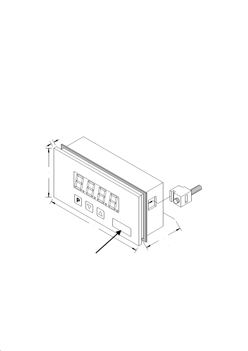
1. After removing the fixing elements, insert the device.
2. Check the seal to make sure it fits securely.
3. Click the fixing elements back into place and tighten the clamping screws by hand. Then
use a screwdriver to tighten them another half a turn.
CAUTION! The torque should not exceed 0.1 Nm!
1. Brief description
The panel instrument M1-1C6 is a 4-digit device for temperature metering via Pt1000-
sensors and a visual limit value monitoring via the display. The configuration happens via
three front keys or via the optional PC-software PM-TOOL. An integrated programming
interlock prevents unrequested changes of the parameter and can be unlocked again via
an individual code.
The electrical connection happens on the rear side via plug-in terminals.
Selectable functions like e.g. the recall of the min/max-value, an impedance matching and
a direct change of the limit value in operating mode complete the modern device concept.
Sealing
48,0
96,0
3,0
38,0
Installation depth
incl. plug-in terminal
Gap for
physical unit

3. Electrical connection
2
3. Electrical connection
Type M1-1VR4B.0001.570xD with a supply of 230 VAC
Type M1-1VR4B.0001.770xD with a supply of 24 VDC, galv. isolated
Advice:
The galvanic isolation in devices with temperature sensors, that do not have a galvanic
connection to an extrinsic potential, can be cancelled by an bridge from terminal 3 to 4 and
thus stabilise the device against external failures.
Devices with a supply of 230 VAC need to connect terminal 3 to signal ground.
1 2 3 4 5
Pt1000
2-wire
N L
230 VAC
3 VA
<
_
1 2 3 4 5
Pt1000
2-wire
_+
24 VDC
<
_
1 VA

4. Function description and operation
3
4. Function description and operation
4.1. Programming via configuration software PM-TOOL-MUSB4:
You receive the software on CD incl. an USB-cable with a device adapter. The connection
happens via a 4-pole micromatch connector plug on the back and the PC is connected via
an USB connector plug.
System requirements: PC with USB interface
Software: Windows XP, Windows Vista
With this tool the device configuration can be created, skipped and saved on the PC. Via the
easy to handle program surface the parameter can be changed, whereat the mode of
operation and the possible selection options can be preset via the program.
CAUTION! During parameterisation with connected measuring signal, make sure that the
measuring signal has no mass supply to the programming plug. The programming adapter is
galvanic not isolated and directly connected with the PC. Via polarity of the input signal, a
current can discharge via the adapter and destroy the device as well as other connected
components!
Level Button Description
Menu level
Change to parameterisation level with the relevant
parameters.
For navigation at the menu level.
Parameterisation
level
To confirm the changes made at the parameterisation
level.
To change the value or setting.
Operation
The operation is divided into two different levels.
Menu Level
Here it is possible to navigate between the individual menu items.
Parameterization level:
The parameters stored in the menu item can be parameterized here.
Functions that can be adjusted or changed, are always indicated with a flashing of the display.
Adjustments made at the parameterisation level should always be confirmed by pressing the
[P]-key to save them. However, the display automatically saves all adjustments and then
switches into operation mode if no further keys are pressed within 10 seconds.
Menu level Parameterisation level
Example:

4
5.1. Switching on
Once the installation is complete, start the device by applying the current loop. Check
beforehand once again that all the electrical connections are correct.
Starting sequence
For 1 second during the switching-on process, the segment test ( ) is displayed,
followed by an indication of the software type and, after that, also for 1 second, the software
version. After the start-up sequence, the device switches to operation/display mode.
5.2. Standard parameterization:
To be able to parameterize the display, press the [P] key in operating mode for 1 second.
The display then changes to the menu level with the first menu item .
5. Setting up the device
Menu level Parameterization level
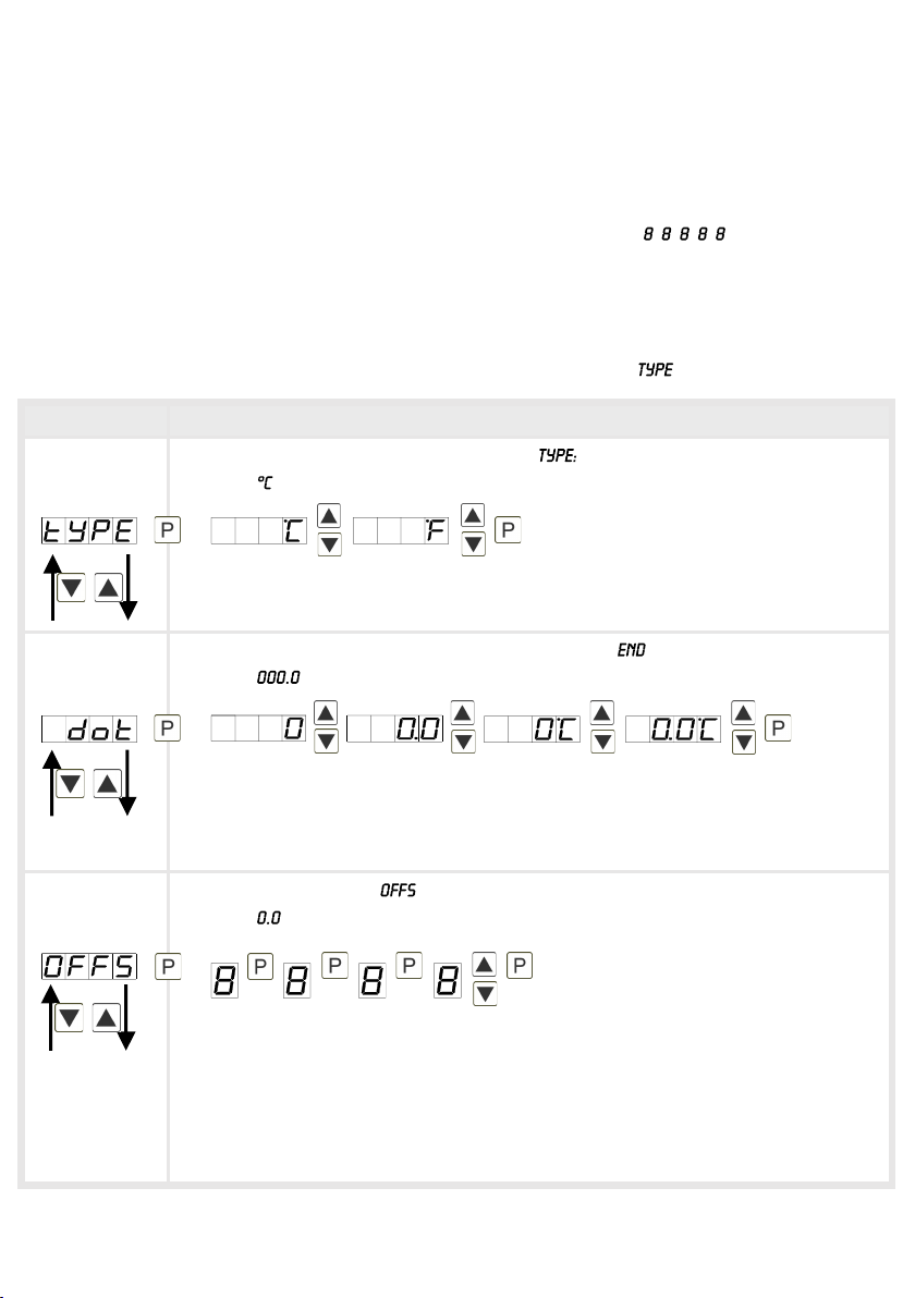
Type of the temperature measurement,
Default:
For representing of temperature choose between °C and °F and confirm with [P].
The display then switches back to the menu level again.
Setting the decimal place / sign of physical unit, :
Default:
The decimal place and the physical unit are set with [▼] [▲]. If e.g. the
temperature measurement is chosen in °C, 0°C or 0.0°C can be selected on the
parameterization level. Confirm with [P], the display then switches back to the
menu level again.
Impedance matching, :
Default:
The value for the sensor alignment is adjusted from the smallest to the highest
place with [▼] [▲] and confirmed digit per digit with [P]. After the last place the
display switches back to the menu level. The value alignment for a temperature
measurement in °C can be set between -20.0 and +20.0 and for a measurement in
°F between -36.0 and +36.0. If the measurement is redirected later, the value is
rounded.

5
5. Setting up the device
Menu level Parameterization level
Setting the display time, :
Default:
The display time is set with [▲] [▼]. The display moves up in increments of 0.1
sec up to 1 second and in increments of 1.0 to 10.0 seconds. Confirm the selection
by pressing the [P] button. The display then switches back to the menu level
again.
5.3. Programming interlock
Activation / deactivation of the programming lock and completion of the
standard parameterization,
Default:
Choose between the deactivated key lock (works setting) and the activated
key lock with the navigation keys [▲] [▼]. Make the selection with [P]. After
this, the display confirms the settings with ", and automatically switches into
operating mode. If was selected, the keyboard is locked. To get back into the
menu level, press [P] for 3 seconds in operating mode. Now enter the (works
setting ) that appears using the [▲] [▼] keys plus [P] to unlock the keyboard.
appears if the input is wrong.
then

6
5. Setting up the device
Menu level Parameterization level
Min/max-value inquiry - assignment of key functions,
Default:
Here, you can enter for the operating mode either a min/max-value inquiry or a
threshold value correction on the arrow keys.
If the min/max-memory is activated with , the measured min/max-values will
be saved during operation and can be called up via the arrow keys [▲] [▼]. When
the device is restarted or the buttons are pressed simultaneously, the values are
lost or deleted.
If the threshold value correction is selected, the limit values can be changed
during operation without hindering the operating procedure. If is parameterized,
the navigation keys [▼] [▲] have no function in operating mode.
Flashing of display,
Default:
Here, flashing of the display can be added as an extra alarm function, either to the
first limit value (select: ), the second limit value (select: ) or to both limit
values (select: ). With (works setting), no flashing is assigned at all.
Limit values / limits,
Default:
For both limit values, two different values can be parameterized. With this, the
parameters for each limit value are called up one after the other.
Hysteresis for limit values,
Default:
For both limit values, a hysteresis function exists that reacts according to the
functional principle (operating current / quiescent current).
5.4. Extended parameterization
By pressing the [▲] &[▼] keys during standard parameterization for one second, the display
switches to the extended parameterization mode. Operation is the same as in standard
parameterization.

7
5. Setting up the device
Menu level Parameterization level
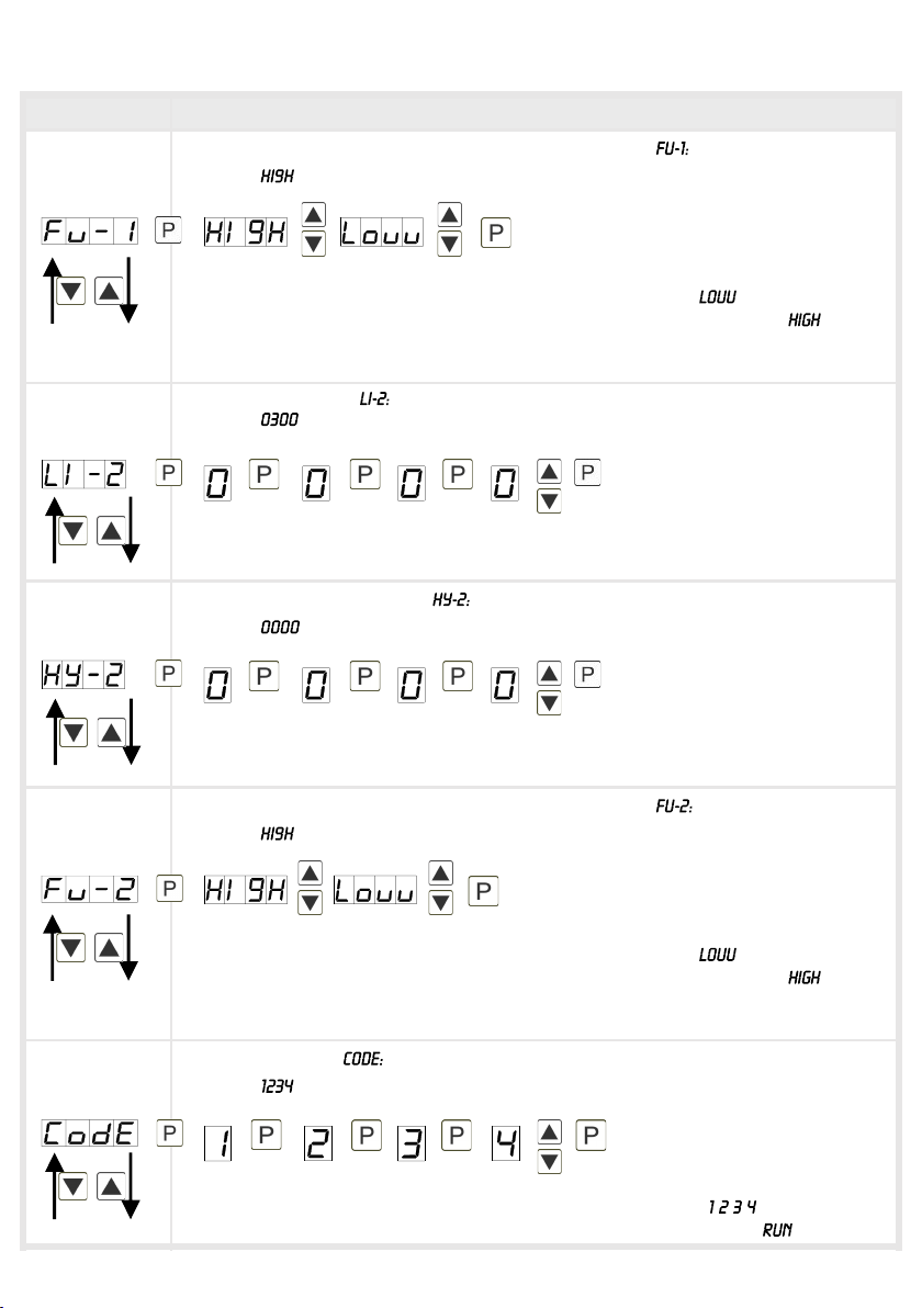
Function if display falls below / exceeds limit value,
Default:
To indicate if the value falls below the lower limit value, can be selected
(LOW = lower limit value) and if it goes above the upper limit value, can be
selected (HIGH = upper limit value). LOW corresponds to the quiescent current
principle and HIGH to the operating current principle.
Limit value / limits,
Default:
For both limit values, two different values can be parameterized. With this, the
parameters for each limit value are called up one after the other.
Hysteresis for limit values,
Default:
For both limit values, a hysteresis function exists that reacts according to the
functional principle (operating current / quiescent current).
Function if display falls below / exceeds limit value,
Default:
To indicate if the value falls below the lower limit value, can be selected
(LOW = lower limit value) and if it goes above the upper limit value, can be
selected (HIGH = upper limit value). LOW corresponds to the quiescent current
principle and HIGH to the operating current principle.
Setting the code,
Default:
Here, it is possible to select an individual code (works setting ) for locking the
keyboard. To lock/release the key, proceed according to menu item .
Altri manuali per M1
6
Indice