Motostar ECLISTAR Manuale utente
ECLISTAR
SWING GATE
OPERATOR
INSTALLATION MANUAL

Pag.
2
- Manual code:
119R7179GB
119 R7179G B ver.
3.0
3.0 07/2009 - The data and information in this manual are subject to change at any time.
INDEX
1.0 General characteristics pag. 2
1.1 Components pag. 3
1.2 Technical features pag. 3
1.3 Dimensions pag. 3
1.4 Main component parts of a standard installation pag. 4
1.5 Limits to use pag. 6
2.0 Installing the gearmotor pag. 7
3.0 Control panel pag. 18
3.1 Assembling and fixing the casing pag. 20
3.2 Control board and its functions – description pag. 22
3.3 Electrical connections pag. 23
3.4 Selecting functions pag. 27
3.5 Adjusting functions pag. 29
3.6 Checking endstops adjustments pag. 30
3.7 Programming the radio code pag. 31
3.8 Control LEDs’ functions pag. 32
3.9 Final operations pag. 32
4.0 Warnings and precautions pag. 33
5.0 Troubleshooting pag. 33
6.0 Maintenance pag. 34
7.0 Dismissal and disposal pag. 36
1.0 GENERAL CHARACTERISTICS
Operator for swing gates up to 2.20 m per gate leaf, 230V A.C. powered, IP54 protection
rating, fitted with:
- autoapprendimento del codice tra trasmettitore e ricevitore radio;
- self-learning of the code between transmitter and radio receiver;
- adjustable amperometric detector for movement inversion of the opening and closing gate
leaves;
- colour-coded terminals to identify the various accessories and simplify connections;
- power up warning LEDs, programming and safety test;
- endstops for managing gate leaf stops when opening and slow-downs when closing;
- emergency release with customised key;
- power cable L = 2.5 m.
x 1 x 2
5
8
6
4
2
13
7
Pag.
3
- Manual code:
119R7179GB
119 R7179G B ver.
3.0
3.0 07/2009 - The data and information in this manual are subject to change at any time.
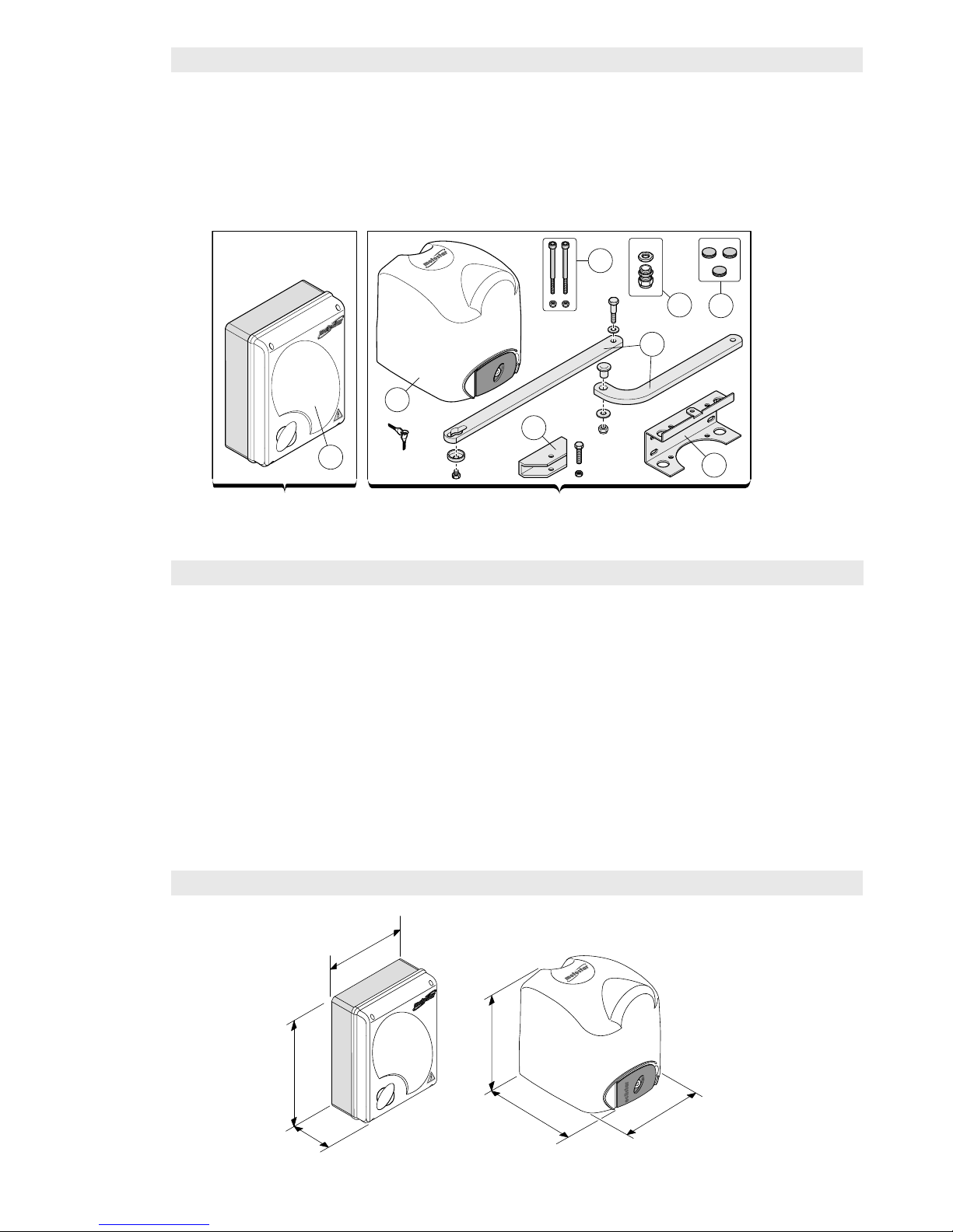
1.1 COMPONENT PARTS
1) Control panel
2) Gearmotor
3) Base bracket
4) Head brackets
5) Fixing nuts and screws
6) Transmission arms
7) Cable feedthroughs
8) Cable gland
1.2 TECHNICAL CHARACTERISTICS
24V D.C. self-locking gearmotor, powered by a 230V A.C. control panel.
1.3 DIMENSIONS
Power supply to control panel:
230V A.C. – 50/60Hz
Power supply to gearmotor:
24V D.C.
Max power: 140W
Nominal supply voltage: 5A max
Max thrust: 180N
Max frequency of use: 45 cycles/h
Duty cycle: 50%
Reduction ratio: 1/36
Operating temperature: from -20° to +
55°C
Overall weight including packaging: 30 Kg
4
6
Ⓑ
Ⓑ
Ⓑ+Ⓔ
Ⓑ+Ⓔ
Pag.
4
-
119R7179GB
119 R7179G B ver.
3.0
3.0 07/2009 - The data and information in this manual are subject to change at any time and without need of prior notice.
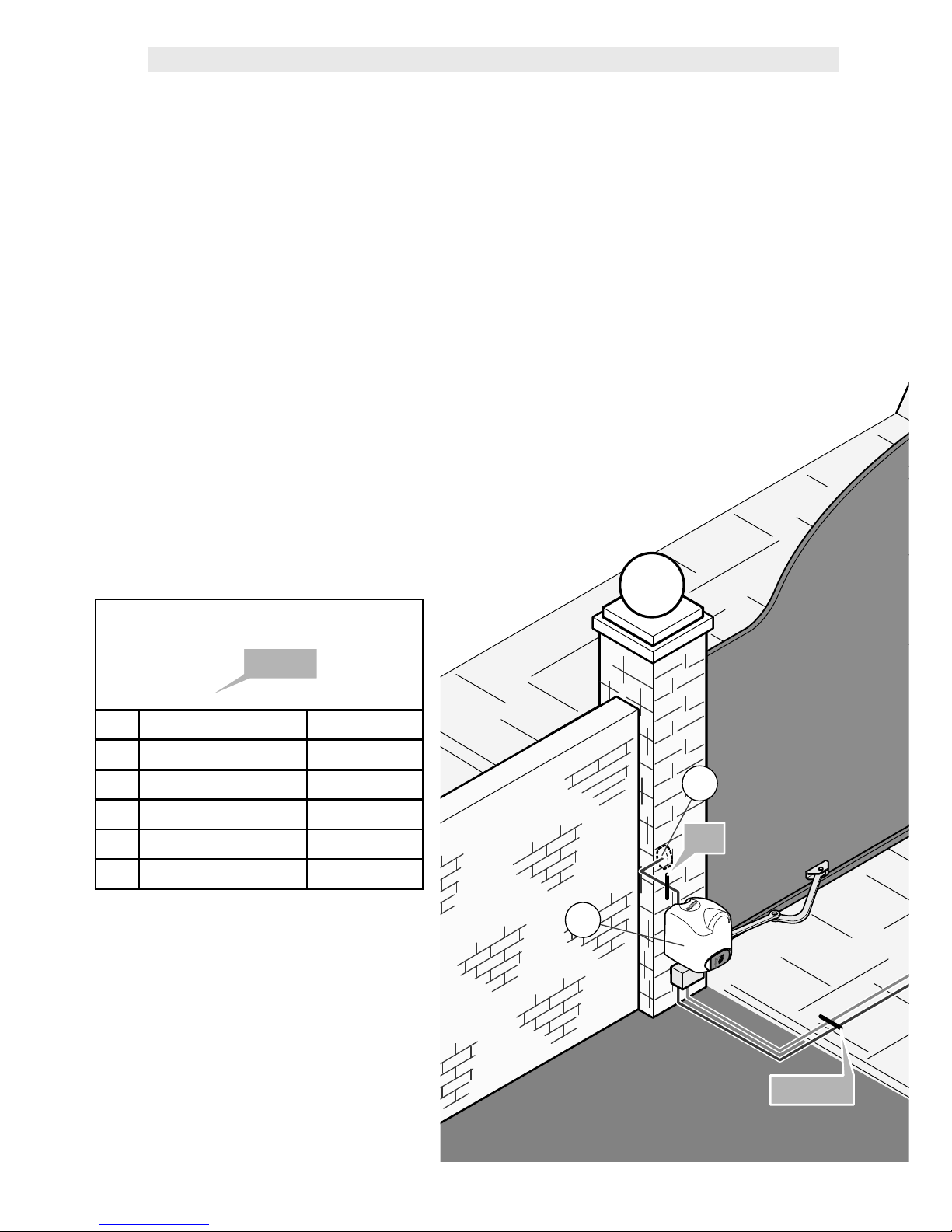
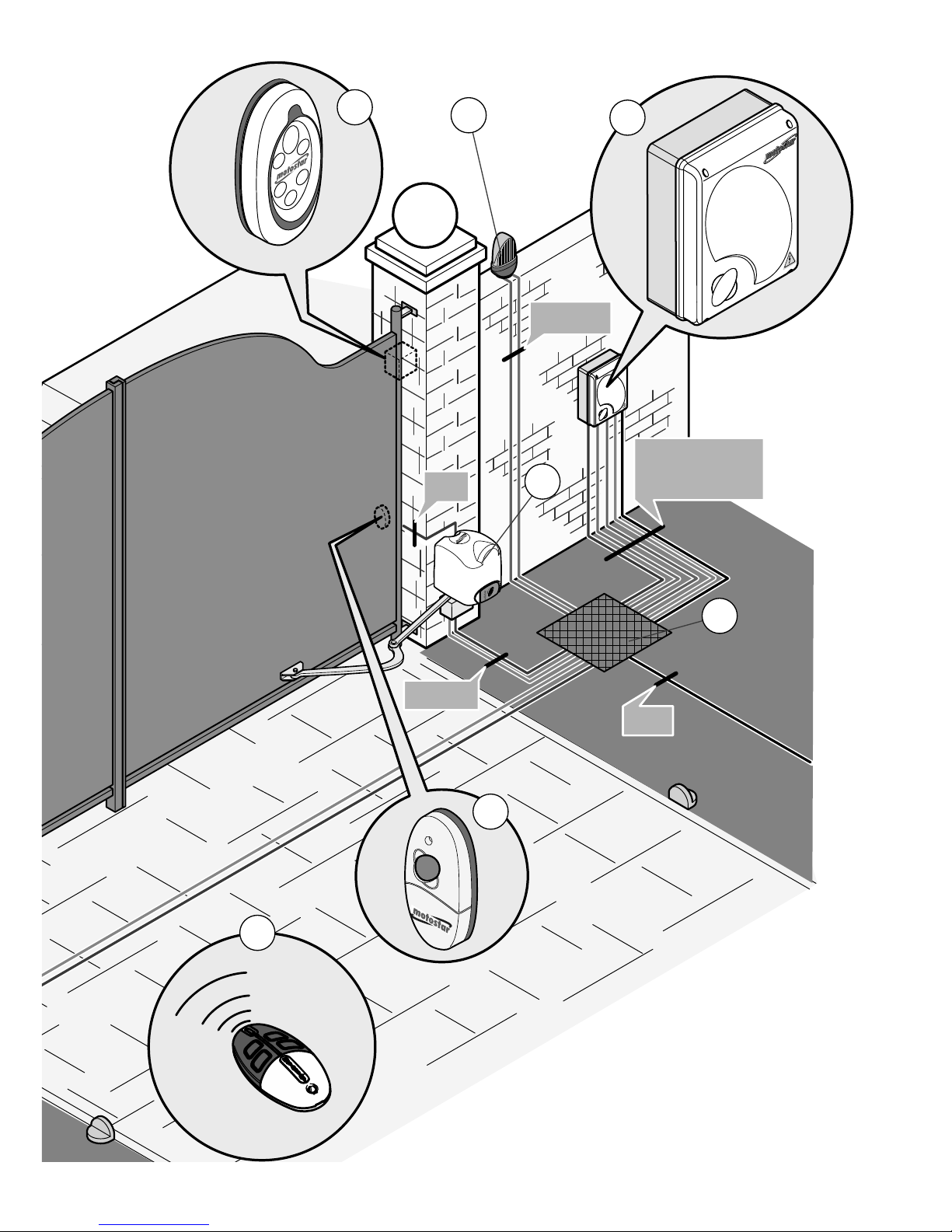
1.4 MAIN COMPONENT PARTS OF A STANDARD INSTALLATION
1) Flashing light with built-in antenna
2) Keypad selector
3) Control panel
4) Photocell
5) Junction box for passage of electrical cables
6) Gearmotors
7) Transmitters
The standard installation shown is only an example.
Check the illustrations and the contents list in the kit box you
have purchased.
Number of wires per cable section
Ⓐ
Ⓐ
+
+
Ⓑ
Ⓑ
ⒶPower supply 3 x 1,5
ⒷRX photocell 4 x 0,5
ⒸTX photocell 2 x 0,5
Ⓓflashing light 2 x 1,5
Ⓔgearmotor 3 x 1,5
Ⓕantenna RG58 cable
12
34
5
E
3
5
1
2
4
6
7
Ⓐ
Ⓐ
Ⓒ+Ⓔ
Ⓒ+Ⓔ
Ⓒ
Ⓒ
Ⓓ+Ⓕ
Ⓓ+Ⓕ
Ⓐ+Ⓑ+Ⓒ
Ⓐ+Ⓑ+Ⓒ
+Ⓓ+Ⓔ+Ⓕ
+Ⓓ+Ⓔ+Ⓕ
The data and information in this manual are subject to change at any time and without need of prior notice -
119R7179GB
119 R7179G B ver.
3.0
3.0 07/2009 - Pag.
5
240
max
AC
330
330
B
(mm)
Pag.
6
- Manual code:
119R7179GB
119 R7179G B ver.
3.0
3.0 07/2009 - The data and information in this manual are subject to change at any time.
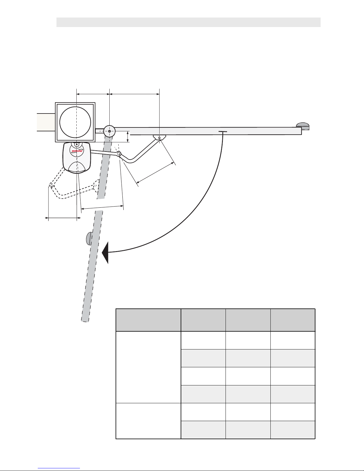
1.5 LIMITS TO USE
Opening angle A B C
90°
140÷205 0÷50 430
140÷195 75÷100 430
140÷185 125÷150 400
140÷175 175÷200 400
110°
180÷210 0 430
200÷205 50 430
The maximum width of the gate leaf must not exceed 2.2 metres and its max weight
cannot exceed 300 kg.
Pag.
7
- Manual code:
119R7179GB
119 R7179G B ver.
3.0
3.0 07/2009 - The data and information in this manual are subject to change at any time.
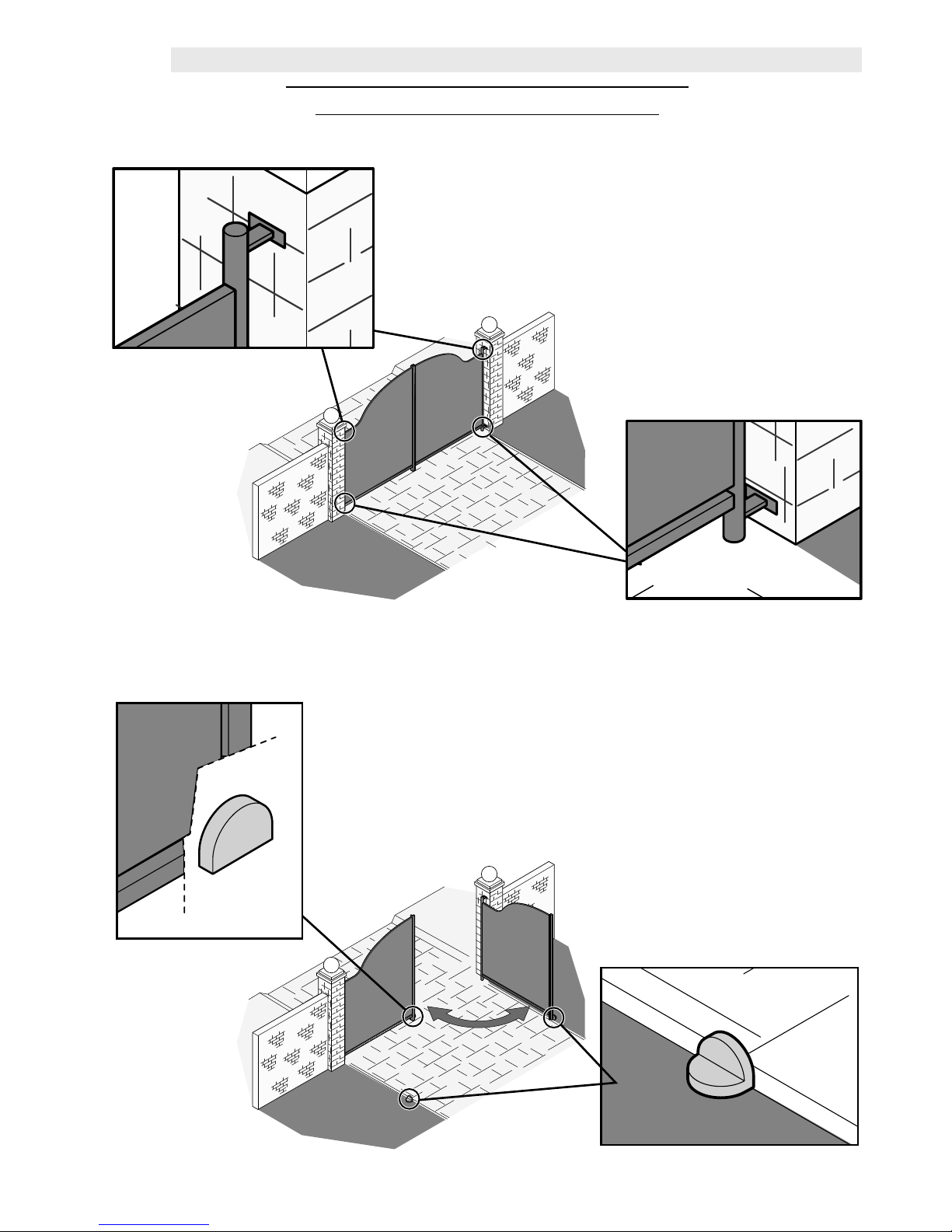
2.0 INSTALLING THE AUTOMATION
GATE CHECKS BEFORE INSTALLING
• Check that the gate structure is sturdy and that
the hinges are in proper condition.
• Make sure that there is a closing and opening
mechanical door endstop (that is well secured to the
ground) to prevent over-run of the gate leaf.
68
100
min.
81.5
40
173
120
120
(mm)
Pag.
8
- Manual code:
119R7179GB
119 R7179G B ver.
3.0
3.0 07/2009 - The data and information in this manual are subject to change at any time.
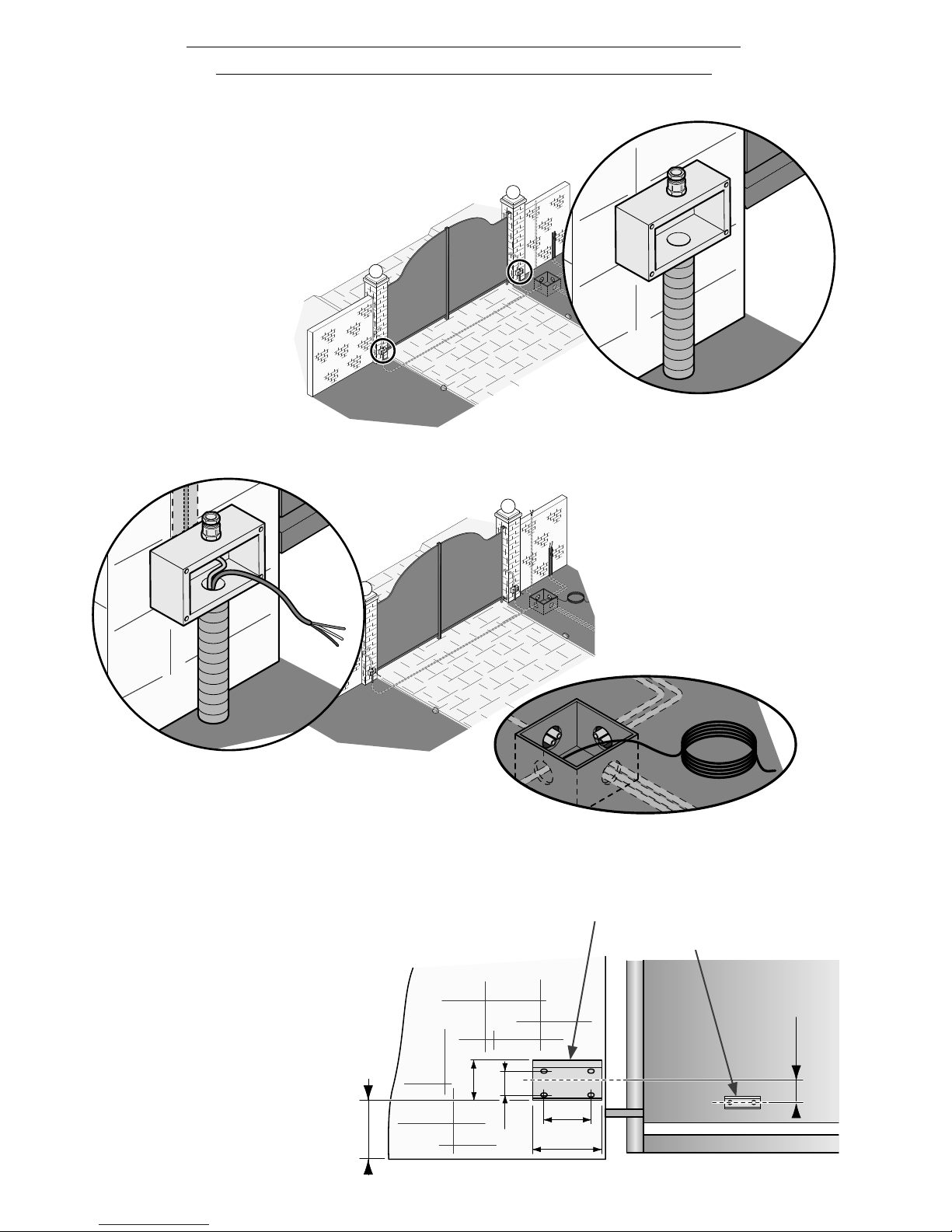
1 - Set up the tubes for the
electrical connection and
junction boxes.
3 - Decide where to fix the head bracket.
Position the base plate on the post,
making sure the fixing and
application measurements
are right (see this drawing)
(see page 6).
2 - Insert the electrical
cables that come
from the junction pit into
the tubes, making sure
the sections are right
depending on the use to
be made (see installation
on page 4).
PRELIMINARY OPERATIONS AND BRACKET MOUNTING
Head bracket
Base plate
22.5
60
100
C
Pag.
9
- Manual code:
119R7179GB
119 R7179G B ver.
3.0
3.0 07/2009 - The data and information in this manual are subject to change at any time.
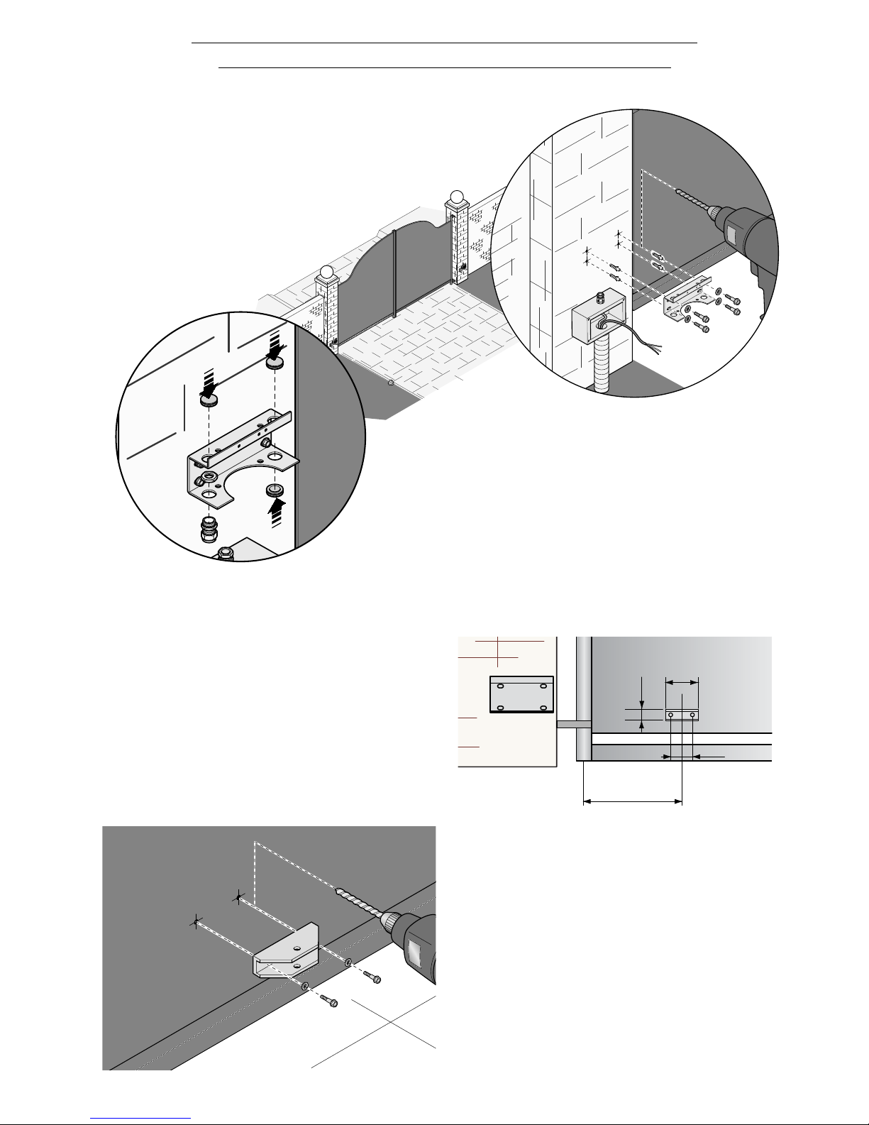
6 - Position the head bracket onto
the gate leaf at a “C” distance from
the axis of the hinge while taking into
account the A and B measurements as
shown in the table on page 6.
7 - Secure the bracket using securing
elements chosen according to the
gate type and materials.
4 - Secure the base plate, using securing
elements chosen according to the post
type and materials.
PRELIMINARY OPERATIONS AND BRACKET MOUNTING
5 - Insert the cable feedthroughs and the
cable gland into the base plate holes.
1
2
Pag.
10
10 - Manual code:
119R7179GB
119 R7179G B ver.
3.0
3.0 07/2009 - The data and information in this manual are subject to change at any time.
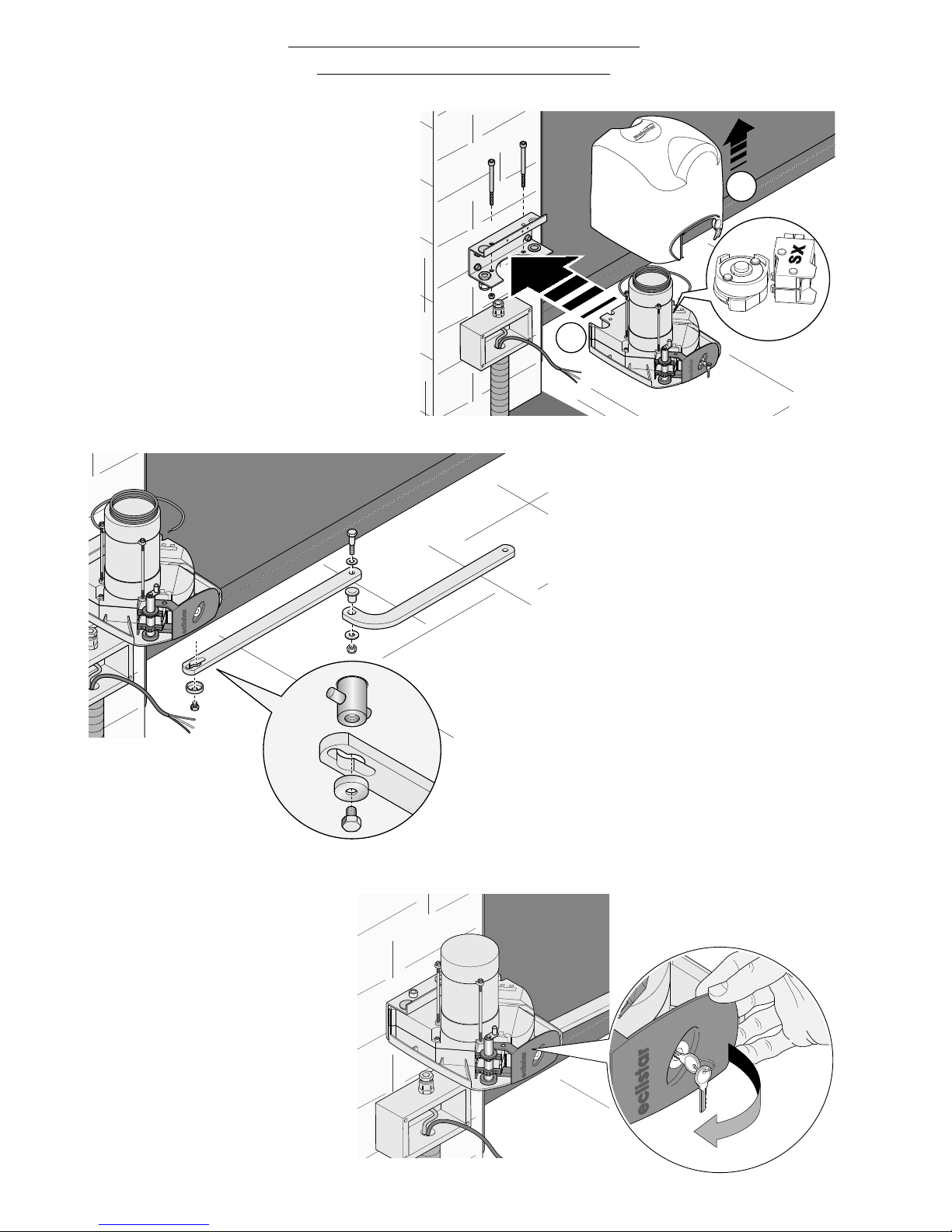
SECURING THE GEARMOTOR
1 - Remove the cover, insert
the gearmotor into the base
bracket so that it corresponds to
the 4 holes and secure it using the
supplied screws and nuts.
Warning: a sticker tag on the microswitch
shows whether that gearmotor should be
mounted to the right (DX) or to the left
(SX).
2 - Insert and secure the
straight arm into the
gearmotor shaft using plug,
screw and relative bushing.
Lubricate the bushing, insert
it into the straight arm and join
it to the curved arm using the
supplied screw, the washers
and nut.
3 -Release the
gearmotor by opening
the hatch (using the
apposite key); to lock it,
close the hatch.
Indice
Altri manuali Motostar Apricancello


